Owner's Manual
Page 3
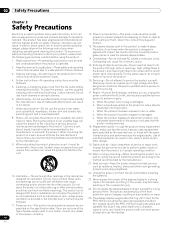
Product Name: Plasma Display System Model Number: PRO-150FD/PRO-110FD Product Category: Class B Personal Computers & Peripherals Responsible Party Name: PIONEER ELECTRONICS SERVICE, INC. If this equipment does cause harmful interference to radio or television reception, which can be performed...Increase the separation between the equipment and receiver. - Connect the equipment into the power outlet. Consult the dealer or an experienced radio/TV technician for the unit, you to chemicals listed on proposition 65 known to the State of California and other governmental entities to high ...
Product Name: Plasma Display System Model Number: PRO-150FD/PRO-110FD Product Category: Class B Personal Computers & Peripherals Responsible Party Name: PIONEER ELECTRONICS SERVICE, INC. If this equipment does cause harmful interference to radio or television reception, which can be performed...Increase the separation between the equipment and receiver. - Connect the equipment into the power outlet. Consult the dealer or an experienced radio/TV technician for the unit, you to chemicals listed on proposition 65 known to the State of California and other governmental entities to high ...
Owner's Manual
Page 4
... unit 16 05 Preparation 17 Installing the plasma display 17 Moving the plasma display 17 Attaching the Pioneer stand 17 Installing the Pioneer speaker 19 Preventing the plasma display from that shown in a safe place for skipping unwanted channels 42 Setting up TV channels manually ........ 42 Checking signal strength... for buying this manual are for the PRO-110FD unless otherwise specified. However the method of the remote control unit 31 06 Basic Operations 32 Turning on the power 32 Turning off the power 32 Watching TV channels 33 Selecting the antenna 33 Changing channels...
... unit 16 05 Preparation 17 Installing the plasma display 17 Moving the plasma display 17 Attaching the Pioneer stand 17 Installing the Pioneer speaker 19 Preventing the plasma display from that shown in a safe place for skipping unwanted channels 42 Setting up TV channels manually ........ 42 Checking signal strength... for buying this manual are for the PRO-110FD unless otherwise specified. However the method of the remote control unit 31 06 Basic Operations 32 Turning on the power 32 Turning off the power 32 Watching TV channels 33 Selecting the antenna 33 Changing channels...
Owner's Manual
Page 7
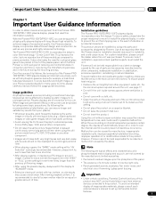
.... 7 En Important User Guidance Information 01 Chapter 1 Important User Guidance Information In order to obtain maximum enjoyment from this Pioneer PRO150FD/PRO-110FD plasma display, please first read and follow the usage guidelines below , you can be installed by using only parts and accessories ... input from a TV, VCR, DVD player or any still image, it is poor. • Do not cover with long-life and high reliability. For the minimum space required around the unit, see page 17. Installation guidelines The Pioneer PRO-150FD/PRO-110FD plasma display incorporates a very...
.... 7 En Important User Guidance Information 01 Chapter 1 Important User Guidance Information In order to obtain maximum enjoyment from this Pioneer PRO150FD/PRO-110FD plasma display, please first read and follow the usage guidelines below , you can be installed by using only parts and accessories ... input from a TV, VCR, DVD player or any still image, it is poor. • Do not cover with long-life and high reliability. For the minimum space required around the unit, see page 17. Installation guidelines The Pioneer PRO-150FD/PRO-110FD plasma display incorporates a very...
Owner's Manual
Page 10
... has been exposed to perform repairs. d. Safety checks-Upon completion of time. Do not expose the plasma display to ensure that the product needs servicing. 18. The plasma display weighs about 66.7 kg (147.0 lbs.) for the PRO-150FD (including the stand and speaker) and about 45.1 kg (99.4 lbs.) for a long period...
... has been exposed to perform repairs. d. Safety checks-Upon completion of time. Do not expose the plasma display to ensure that the product needs servicing. 18. The plasma display weighs about 66.7 kg (147.0 lbs.) for the PRO-150FD (including the stand and speaker) and about 45.1 kg (99.4 lbs.) for a long period...
Owner's Manual
Page 11
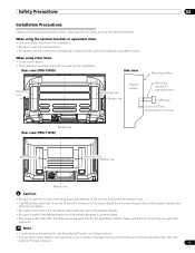
...Pioneer shall not be liable for any personal injury or product damage that comes with any items such as the optional bracket. Safety Precautions 02 Installation Precautions Observe the following mounting holes can be used for the installation: Rear view (PRO-150FD) Side view Mounting surface Mounting hole 4 5 Mounting hole Median line Plasma...the ventilation opening at the rear of mounting items other than the optional Pioneer products. 11 En Never use of the plasma display. • Be sure to install the plasma display on a flat surface because it contains glass. • The...
...Pioneer shall not be liable for any personal injury or product damage that comes with any items such as the optional bracket. Safety Precautions 02 Installation Precautions Observe the following mounting holes can be used for the installation: Rear view (PRO-150FD) Side view Mounting surface Mounting hole 4 5 Mounting hole Median line Plasma...the ventilation opening at the rear of mounting items other than the optional Pioneer products. 11 En Never use of the plasma display. • Be sure to install the plasma display on a flat surface because it contains glass. • The...
Owner's Manual
Page 14
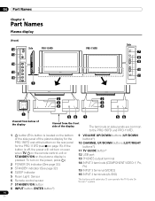
...; system. 14 En To turn on even when TV a on the remote control unit or STANDBY/ON on the plasma display is located on the bottom of the side panel of the display The terminals on side panels are common to the PRO-150FD and PRO-110FD. 1 a button (This button is pressed.... 04 Part Names Chapter 4 Part Names Plasma display (Front) 12 13 Side PRO-150FD 14 15 16 1 PRO-110FD Side 7 8 9 10 11 2 2 3 3 4 4 1 56 1 56 Viewed from below of the...
...; system. 14 En To turn on even when TV a on the remote control unit or STANDBY/ON on the plasma display is located on the bottom of the side panel of the display The terminals on side panels are common to the PRO-150FD and PRO-110FD. 1 a button (This button is pressed.... 04 Part Names Chapter 4 Part Names Plasma display (Front) 12 13 Side PRO-150FD 14 15 16 1 PRO-110FD Side 7 8 9 10 11 2 2 3 3 4 4 1 56 1 56 Viewed from below of the...
Owner's Manual
Page 17
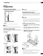
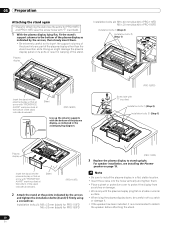
.../detaching the stand varies depending on a rack by detaching the stand. Attaching the Pioneer stand The plasma display comes with a soft sheet placed under the base cover. Insert stand pipe ...around the upper and back parts when installing to ensure adequate ventilation of the rear of a 60 inch plasma display is about 55.5 kg (122.4 lbs.) and a 50 inch about 38.8 kg (...black) to have someone help you when moving it . Screws ➀ (M5 x 10 mm: black) (PRO-110FD) Screws ➀ (M5 x 10 mm: black) Stand pipe with "R" inscribed Rear Completed Table top stand...
.../detaching the stand varies depending on a rack by detaching the stand. Attaching the Pioneer stand The plasma display comes with a soft sheet placed under the base cover. Insert stand pipe ...around the upper and back parts when installing to ensure adequate ventilation of the rear of a 60 inch plasma display is about 55.5 kg (122.4 lbs.) and a 50 inch about 38.8 kg (...black) to have someone help you when moving it . Screws ➀ (M5 x 10 mm: black) (PRO-110FD) Screws ➀ (M5 x 10 mm: black) Stand pipe with "R" inscribed Rear Completed Table top stand...

Owner's Manual
Page 18
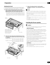
If there is no gaps (See diagram at below). 05 Preparation Attaching the light-blocking shield (PRO-150FD only) This part prevents reflection of the cables connected to the back of the lightblocking shield, apply it after anchoring the base cover on ..., the light-blocking shield may peel off. 3 Anchor it down from the light-blocking shield. Light-blocking shield 2 While firmly holding the ends of the plasma display on a flat stable place. Remove each double-sided adhesive tape. Note • Attach it with the doublesided adhesive tape.
If there is no gaps (See diagram at below). 05 Preparation Attaching the light-blocking shield (PRO-150FD only) This part prevents reflection of the cables connected to the back of the lightblocking shield, apply it after anchoring the base cover on ..., the light-blocking shield may peel off. 3 Anchor it down from the light-blocking shield. Light-blocking shield 2 While firmly holding the ends of the plasma display on a flat stable place. Remove each double-sided adhesive tape. Note • Attach it with the doublesided adhesive tape.
Owner's Manual
Page 19
... the speaker system resulting from the speaker. Sheet (PRO-150FD) 2 Attach the stand at the bottom of the plasma display as the grille net and the cabinet can result in warping of the plasma display other than the plasma display. Installation • When installing the speaker,...please observe the following precautions: • Do not use any part of the stand. For speaker installation, see Installing the Pioneer speaker. Installing the Pioneer speaker Insert the stand into any screws other than the stand insertion slots. Doing so may result in damage or fire....
... the speaker system resulting from the speaker. Sheet (PRO-150FD) 2 Attach the stand at the bottom of the plasma display as the grille net and the cabinet can result in warping of the plasma display other than the plasma display. Installation • When installing the speaker,...please observe the following precautions: • Do not use any part of the stand. For speaker installation, see Installing the Pioneer speaker. Installing the Pioneer speaker Insert the stand into any screws other than the stand insertion slots. Doing so may result in damage or fire....

Owner's Manual
Page 20
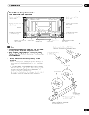
... bottom on the back of the speakers using the hang on wall unit, first lay the plasma display on top of the fitting on the right side. 05 Preparation PRO-150FD with the speaker installed (with the Pioneer table top stand) Speaker mounting fitting (for TOP-Right) Speaker mounting screw (M5 x 10 mm...
... bottom on the back of the speakers using the hang on wall unit, first lay the plasma display on top of the fitting on the right side. 05 Preparation PRO-150FD with the speaker installed (with the Pioneer table top stand) Speaker mounting fitting (for TOP-Right) Speaker mounting screw (M5 x 10 mm...
Owner's Manual
Page 23
Preparation 05 PRO-110FD with the speaker installed (with the Pioneer table top stand) Speaker mounting fitting (for TOP-Right) Speaker mounting screw (M5 x 10 mm) Speaker mounting screw (M5 x 10 mm) Speaker mounting screw (M5 x ...) Speaker cable Speed clamp Speed clamp Speaker mounting screw (M5 x 10 mm) Note • Before installing the speaker, make sure that the Pioneer table top stand is attached to the plasma display. • When using the supplied screws. (It shows the attachment of a soft sheet, etc., remove the stand, then attach the...
Preparation 05 PRO-110FD with the speaker installed (with the Pioneer table top stand) Speaker mounting fitting (for TOP-Right) Speaker mounting screw (M5 x 10 mm) Speaker mounting screw (M5 x 10 mm) Speaker mounting screw (M5 x ...) Speaker cable Speed clamp Speed clamp Speaker mounting screw (M5 x 10 mm) Note • Before installing the speaker, make sure that the Pioneer table top stand is attached to the plasma display. • When using the supplied screws. (It shows the attachment of a soft sheet, etc., remove the stand, then attach the...
Owner's Manual
Page 26
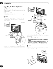
... or rack Stabilize the plasma display as shown in the middle at the rear of the tabletop panel before using the supplied plastic bands and screws. Drill a hole in the diagram using a wood screw. Perform this work in the middle at least 20 mm (13/16 inch) long. (PRO-150FD) 20 mm... min. (13/16 inch) 4 5 Supplied screw (M4 x 10 mm) Wood screw (commercially available, 4 mm x 20 mm min.) (5/32 inch x 13/16 inch) (PRO-110FD) 20 mm min. (13/16 inch) 4 5 Supplied screw Wood screw Supplied screw (M4 x 10 mm) Wood screw (commercially available, 4 mm x 20 mm min.) (5/32 ...
... or rack Stabilize the plasma display as shown in the middle at the rear of the tabletop panel before using the supplied plastic bands and screws. Drill a hole in the diagram using a wood screw. Perform this work in the middle at least 20 mm (13/16 inch) long. (PRO-150FD) 20 mm... min. (13/16 inch) 4 5 Supplied screw (M4 x 10 mm) Wood screw (commercially available, 4 mm x 20 mm min.) (5/32 inch x 13/16 inch) (PRO-110FD) 20 mm min. (13/16 inch) 4 5 Supplied screw Wood screw Supplied screw (M4 x 10 mm) Wood screw (commercially available, 4 mm x 20 mm min.) (5/32 ...
Owner's Manual
Page 27
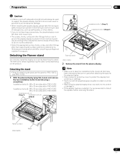
... the stand from the plasma display. Installation bolts (1): M8 x 23 mm (black) for PRO-110FD M6 x 20 mm (black) for PRO-150FD Installation bolts (2): M8 x 40 mm (black) for PRO-110FD M6 x 20 mm (black) for attaching/detaching the stand varies depending on a rack by detaching the stand. Detaching the Pioneer stand You can also...
... the stand from the plasma display. Installation bolts (1): M8 x 23 mm (black) for PRO-110FD M6 x 20 mm (black) for PRO-150FD Installation bolts (2): M8 x 40 mm (black) for PRO-110FD M6 x 20 mm (black) for attaching/detaching the stand varies depending on a rack by detaching the stand. Detaching the Pioneer stand You can also...
Owner's Manual
Page 28
... speaker installation, see Installing the Pioneer speaker on a table or similar surface. • When lying the plasma display down, be careful not to scratch or damage it. • If the speaker has been installed, it is recommended to stand upright. Sheet (PRO-110FD) 2 Attach the stand ... a screwdriver. Installation bolts (1): M8 x 23 mm (black) for PRO-110FD M6 x 20 mm (black) for PRO-150FD (PRO-110FD) 3 Replace the plasma display to detach the speaker before attaching the stand. 28 En Doing so might damage the plasma display panel or its ports or result in a flat, stable location...
... speaker installation, see Installing the Pioneer speaker on a table or similar surface. • When lying the plasma display down, be careful not to scratch or damage it. • If the speaker has been installed, it is recommended to stand upright. Sheet (PRO-110FD) 2 Attach the stand ... a screwdriver. Installation bolts (1): M8 x 23 mm (black) for PRO-110FD M6 x 20 mm (black) for PRO-150FD (PRO-110FD) 3 Replace the plasma display to detach the speaker before attaching the stand. 28 En Doing so might damage the plasma display panel or its ports or result in a flat, stable location...
Owner's Manual
Page 30
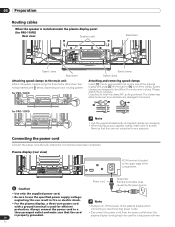
... to the main unit Attach the speed clamps using the three holes (60 inches: four holes) marked with a ground terminal is used for efficient protection. 05 Preparation Routing cables When the speaker is installed under the plasma display panel (for PRO-110FD Speed clamp Speed clamp Attaching and removing speed clamps Insert [1] into...
... to the main unit Attach the speed clamps using the three holes (60 inches: four holes) marked with a ground terminal is used for efficient protection. 05 Preparation Routing cables When the speaker is installed under the plasma display panel (for PRO-110FD Speed clamp Speed clamp Attaching and removing speed clamps Insert [1] into...
Owner's Manual
Page 32
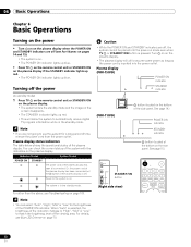
... of the system with the indicators on the plasma display. Plasma display (PRO-150FD) POWER ON indicator STANDBY indicator (PRO-110FD) a button (located on the bottom of the plasma display is on. • The POWER ON indicator lights up blue. • Press TV a on the remote control unit or STANDBY/...ON on the plasma display if the STANDBY indicator lights up red. &#...
... of the system with the indicators on the plasma display. Plasma display (PRO-150FD) POWER ON indicator STANDBY indicator (PRO-110FD) a button (located on the bottom of the plasma display is on. • The POWER ON indicator lights up blue. • Press TV a on the remote control unit or STANDBY/...ON on the plasma display if the STANDBY indicator lights up red. &#...

Owner's Manual
Page 61
... Settings 11 Advanced picture adjustments The plasma display provides various advanced functions for images...signals: 480p, 720p@60 Hz, 1080p@60 Hz. • "Smooth" is not selectable for the following input signals: 1080p@60 Hz. • "Advance" is not selectable for the following input signals: 1080p@60 Hz. • ...then ENTER). 5 Select an item to be seen on the screen. Using PureCinema 1 Press HOME MENU. 2 Select "Picture" ( / then ENTER). 3 Select "Pro Adjust" ( / then ENTER). 4 Select "PureCinema" ( / then ENTER). 5 Select "Film Mode" or "Text Optimization" ( / then ENTER). 6 Select ...
... Settings 11 Advanced picture adjustments The plasma display provides various advanced functions for images...signals: 480p, 720p@60 Hz, 1080p@60 Hz. • "Smooth" is not selectable for the following input signals: 1080p@60 Hz. • "Advance" is not selectable for the following input signals: 1080p@60 Hz. • ...then ENTER). 5 Select an item to be seen on the screen. Using PureCinema 1 Press HOME MENU. 2 Select "Picture" ( / then ENTER). 3 Select "Pro Adjust" ( / then ENTER). 4 Select "PureCinema" ( / then ENTER). 5 Select "Film Mode" or "Text Optimization" ( / then ENTER). 6 Select ...
Owner's Manual
Page 123
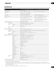
... 5 INPUT 6 INPUT 7 AUDIO OUT IR REPEATER OUT DIGITAL OUT ETHERNET CONTROL OUT SPEAKERS SUB WOOFER CableCARD Side INPUT 3 PHONES USB On-screen display languages 60" plasma display model: PRO-150FD 1920 × 1080 pixels 17 W + 17 W (1 kHz, 10 %, 6 Ω) Woofer: 6.6 cm x 10.6 cm cone type Tweeter: ...(including cables, mounting fittings and screws) Total: 66.7 kg (147.0 lbs.) ATSC Digital TV system 8VSB/64QAM/256QAM/QPSK demodulation VHF Ch. 2 to 13 UHF Ch. 14 to 69 Ch. 2 to 135 Dolby Digital 50" plasma display model: PRO-110FD 17 W + 17 W (1 kHz, 10 %, 6 Ω) SRS FOCUS/SRS...
... 5 INPUT 6 INPUT 7 AUDIO OUT IR REPEATER OUT DIGITAL OUT ETHERNET CONTROL OUT SPEAKERS SUB WOOFER CableCARD Side INPUT 3 PHONES USB On-screen display languages 60" plasma display model: PRO-150FD 1920 × 1080 pixels 17 W + 17 W (1 kHz, 10 %, 6 Ω) Woofer: 6.6 cm x 10.6 cm cone type Tweeter: ...(including cables, mounting fittings and screws) Total: 66.7 kg (147.0 lbs.) ATSC Digital TV system 8VSB/64QAM/256QAM/QPSK demodulation VHF Ch. 2 to 13 UHF Ch. 14 to 69 Ch. 2 to 135 Dolby Digital 50" plasma display model: PRO-110FD 17 W + 17 W (1 kHz, 10 %, 6 Ω) SRS FOCUS/SRS...


