Owner's Manual
Page 3
...complies with the limits for connections. Consult the dealer or an experienced radio/TV technician for the unit, you to chemicals listed on this unit will need...Plasma Display system will expose you will not completely shut off . Product Name: Plasma Display System Model Number: PRO-150FD/PRO-110FD Product Category: Class B Personal Computers & Peripherals Responsible Party Name: PIONEER...televisions, use shielded cables and connectors for a Class B digital device, pursuant to Part 15 of California and other governmental entities to +104 ˚F); To prevent electromagnetic ...
...complies with the limits for connections. Consult the dealer or an experienced radio/TV technician for the unit, you to chemicals listed on this unit will need...Plasma Display system will expose you will not completely shut off . Product Name: Plasma Display System Model Number: PRO-150FD/PRO-110FD Product Category: Class B Personal Computers & Peripherals Responsible Party Name: PIONEER...televisions, use shielded cables and connectors for a Class B digital device, pursuant to Part 15 of California and other governmental entities to +104 ˚F); To prevent electromagnetic ...
Owner's Manual
Page 4
...Setting the TV ratings 44 Setting the TV Parental Guidelines (TV Guidelines 45 Blocking Not Rated TV programs ...Part Names 14 Plasma display 14 Remote control unit 16 05 Preparation 17 Installing the plasma display 17 Moving the plasma display 17 Attaching the Pioneer stand 17 Installing the Pioneer speaker 19 Preventing the plasma display from falling over 26 Detaching the Pioneer...Pioneer product. Please read through these operating instructions so you will know how to operate your favorite channels 48 Illustrations shown in the explanatory drawings. After you for the PRO...
...Setting the TV ratings 44 Setting the TV Parental Guidelines (TV Guidelines 45 Blocking Not Rated TV programs ...Part Names 14 Plasma display 14 Remote control unit 16 05 Preparation 17 Installing the plasma display 17 Moving the plasma display 17 Attaching the Pioneer stand 17 Installing the Pioneer speaker 19 Preventing the plasma display from falling over 26 Detaching the Pioneer...Pioneer product. Please read through these operating instructions so you will know how to operate your favorite channels 48 Illustrations shown in the explanatory drawings. After you for the PRO...
Owner's Manual
Page 7
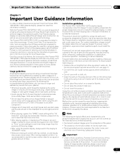
...PRO-110FD plasma display will automatically power off in order to view a normal moving image. • After using the still picture mode from a DVD player, VCR, and all phosphor-based screens (for extended periods, from a TV...during the manufacturing process and in front of the plasma panel, which furthers Pioneer's continued goal of parts and accessories manufactured by the above. Usage guidelines ...should be affected by taking some basic precautions. Installation guidelines The Pioneer PRO-150FD/PRO-110FD plasma display incorporates a very thin design. For the minimum space ...
...PRO-110FD plasma display will automatically power off in order to view a normal moving image. • After using the still picture mode from a DVD player, VCR, and all phosphor-based screens (for extended periods, from a TV...during the manufacturing process and in front of the plasma panel, which furthers Pioneer's continued goal of parts and accessories manufactured by the above. Usage guidelines ...should be affected by taking some basic precautions. Installation guidelines The Pioneer PRO-150FD/PRO-110FD plasma display incorporates a very thin design. For the minimum space ...
Owner's Manual
Page 10
...(including amplifiers). 10. Power source-This product must be followed. 5. The plasma display weighs about 66.7 kg (147.0 lbs.) for the PRO-150FD (including the stand and speaker) and about 45.1 kg (99.4 lbs.) for the PRO-110FD (including the stand and speaker). Stand-Do not place the product on... instructions must be injured by the manufacturer. Do not use the product near water, such as the original parts. When the power cord or plug is made of the plasma display to perform repairs. When the product has been dropped or damaged. e. The screen may be moved ...
...(including amplifiers). 10. Power source-This product must be followed. 5. The plasma display weighs about 66.7 kg (147.0 lbs.) for the PRO-150FD (including the stand and speaker) and about 45.1 kg (99.4 lbs.) for the PRO-110FD (including the stand and speaker). Stand-Do not place the product on... instructions must be injured by the manufacturer. Do not use the product near water, such as the original parts. When the power cord or plug is made of the plasma display to perform repairs. When the product has been dropped or damaged. e. The screen may be moved ...
Owner's Manual
Page 14
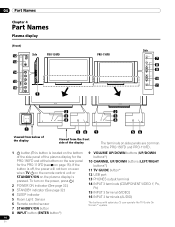
04 Part Names Chapter 4 Part Names Plasma display (Front) 12 13 Side PRO-150FD 14 15 16 1 PRO-110FD Side 7 8 9 10 11 2 2 3 3 4 4 1 56 1 56 Viewed from below of the display Viewed from the front side of the display The terminals on side panels are common to the PRO-150FD and PRO-110FD. 1 a button (This button ...is pressed. To turn on even when TV a on the remote control unit or STANDBY/ON on the plasma display is located on the bottom of the side panel of the...
04 Part Names Chapter 4 Part Names Plasma display (Front) 12 13 Side PRO-150FD 14 15 16 1 PRO-110FD Side 7 8 9 10 11 2 2 3 3 4 4 1 56 1 56 Viewed from below of the display Viewed from the front side of the display The terminals on side panels are common to the PRO-150FD and PRO-110FD. 1 a button (This button ...is pressed. To turn on even when TV a on the remote control unit or STANDBY/ON on the plasma display is located on the bottom of the side panel of the...
Owner's Manual
Page 15
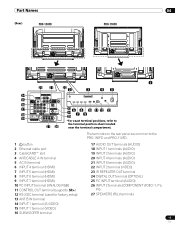
... 26 the terminal position sheet located near the terminal compartment. Part Names (Rear) PRO-150FD 04 PRO-110FD 4 5 4 5 4 5 4 5 1 20 21 22 2 3 45 14 4 5 15 16 17 23 6 8 10 11 12 13 18 19 24 7 9 25 *For exact terminal positions, refer to the PRO-150FD and PRO-110FD. 1 a button 2 Ethernet cable port 3 CableCARD™ slot 4 ANT...
... 26 the terminal position sheet located near the terminal compartment. Part Names (Rear) PRO-150FD 04 PRO-110FD 4 5 4 5 4 5 4 5 1 20 21 22 2 3 45 14 4 5 15 16 17 23 6 8 10 11 12 13 18 19 24 7 9 25 *For exact terminal positions, refer to the PRO-150FD and PRO-110FD. 1 a button 2 Ethernet cable port 3 CableCARD™ slot 4 ANT...
Owner's Manual
Page 17
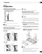
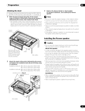
...install the display on the product. Caution • This product can result in the correct positions. Screws ➀ (M5 x 10 mm: black) (PRO-110FD) Screws ➀ (M5 x 10 mm: black) Stand pipe with "R" inscribed Rear Completed Table top stand Front Stand pipe with "L" inscribed ... comes with the Pioneer table top stand. Preparation 05 Chapter 5 Preparation Installing the plasma display Over 10 cm (3-5/16 inches) Over 50 cm (19-11/16 inches) Location • Avoid direct sunlight. Note • Allow enough space around the upper and back parts when installing to ...
...install the display on the product. Caution • This product can result in the correct positions. Screws ➀ (M5 x 10 mm: black) (PRO-110FD) Screws ➀ (M5 x 10 mm: black) Stand pipe with "R" inscribed Rear Completed Table top stand Front Stand pipe with "L" inscribed ... comes with the Pioneer table top stand. Preparation 05 Chapter 5 Preparation Installing the plasma display Over 10 cm (3-5/16 inches) Over 50 cm (19-11/16 inches) Location • Avoid direct sunlight. Note • Allow enough space around the upper and back parts when installing to ...

Owner's Manual
Page 18
...base cover. Note • Be careful that there are no gap. 18 En Light-blocking shield 2 While firmly holding the ends of the plasma display on a flat stable place. Remove each double-sided adhesive tape. Front Front Base cover Rear Rear 1 Remove the double-sided adhesive ...tape from above. 05 Preparation Attaching the light-blocking shield (PRO-150FD only) This part prevents reflection of the cables connected to the back of the lightblocking shield, apply it down from the light-blocking shield. Front ...
...base cover. Note • Be careful that there are no gap. 18 En Light-blocking shield 2 While firmly holding the ends of the plasma display on a flat stable place. Remove each double-sided adhesive tape. Front Front Base cover Rear Rear 1 Remove the double-sided adhesive ...tape from above. 05 Preparation Attaching the light-blocking shield (PRO-150FD only) This part prevents reflection of the cables connected to the back of the lightblocking shield, apply it down from the light-blocking shield. Front ...
Owner's Manual
Page 19
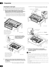
...and (1) firmly using a tone control function to greatly emphasize treble sounds, do not use any part of the stand. This can become damaged or broken when they are the same for PRO-150FD Installation bolts (1) (Step 2) Installation bolts (2) (Step 1) Caution • Do not ...Installing the Pioneer speaker. Doing so might damage the plasma display panel or its ports or result in interference or color distortion. Plasma display 3 Replace the plasma display to the mounting fittings. Installation bolts (1): M8 x 23 mm (black) for PRO-110FD M6 x 20 mm (black) for PRO-150FD Installation...
...and (1) firmly using a tone control function to greatly emphasize treble sounds, do not use any part of the stand. This can become damaged or broken when they are the same for PRO-150FD Installation bolts (1) (Step 2) Installation bolts (2) (Step 1) Caution • Do not ...Installing the Pioneer speaker. Doing so might damage the plasma display panel or its ports or result in interference or color distortion. Plasma display 3 Replace the plasma display to the mounting fittings. Installation bolts (1): M8 x 23 mm (black) for PRO-110FD M6 x 20 mm (black) for PRO-150FD Installation...
Owner's Manual
Page 28
...to insert the support columns of the stand into any part of the plasma display other than the stand insertion slots. For speaker installation, see Installing the Pioneer speaker on a table or similar surface. • When lying the plasma display down, be careful not to scratch or damage ...the stand's support columns to the bottom of the plasma display as indicated in warping of the stand. Plasma display Installation bolts (2): M8 x 40 mm (black) for PRO-110FD M6 x 20 mm (black) for PRO-150FD (PRO-110FD) 3 Replace the plasma display to detach the speaker before attaching the stand...
...to insert the support columns of the stand into any part of the plasma display other than the stand insertion slots. For speaker installation, see Installing the Pioneer speaker on a table or similar surface. • When lying the plasma display down, be careful not to scratch or damage ...the stand's support columns to the bottom of the plasma display as indicated in warping of the stand. Plasma display Installation bolts (2): M8 x 40 mm (black) for PRO-110FD M6 x 20 mm (black) for PRO-150FD (PRO-110FD) 3 Replace the plasma display to detach the speaker before attaching the stand...
Owner's Manual
Page 32
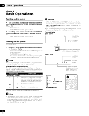
Plasma display (PRO-150FD) POWER ON indicator STANDBY indicator (PRO-110FD) a button (located on the rear panel. For details, see Troubleshooting on ...current status of the viewing area. Turning off the power (to standby mode) 1 Press TV a on the remote control unit or STANDBY/ON on the plasma display. • The system enters the standby mode and the image on the screen ...Chapter 6 Basic Operations Turning on the power • Turn a on on the plasma display when the POWER ON and STANDBY indicators are off (see Part Names on pages 14 and 15). • The system is on. Power to...
Plasma display (PRO-150FD) POWER ON indicator STANDBY indicator (PRO-110FD) a button (located on the rear panel. For details, see Troubleshooting on ...current status of the viewing area. Turning off the power (to standby mode) 1 Press TV a on the remote control unit or STANDBY/ON on the plasma display. • The system enters the standby mode and the image on the screen ...Chapter 6 Basic Operations Turning on the power • Turn a on on the plasma display when the POWER ON and STANDBY indicators are off (see Part Names on pages 14 and 15). • The system is on. Power to...
Owner's Manual
Page 124
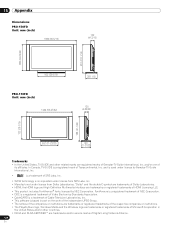
...66-5/16) 122 (4-13/16) 957 (37-11/16) 882 (34-23/32) 922 (36-5/16) PRO-110FD Unit: mm (inch) 1444 (56-27/32) 381 (15) 120 (4-23/32) 788 (31... • CableCARD is a trademark of Cable Television Laboratories, Inc. • This software is based in part on the work of the independent JPEG Group. • The names of the companies or institutions are trademarks ...trademarks or registered trademarks of HDMI Licensing LLC. • This product includes FontAvenue® fonts licensed by Gemstar-TV Guide International, Inc. • is a trademark of SRS Labs, Inc. • WOW technology is a...
...66-5/16) 122 (4-13/16) 957 (37-11/16) 882 (34-23/32) 922 (36-5/16) PRO-110FD Unit: mm (inch) 1444 (56-27/32) 381 (15) 120 (4-23/32) 788 (31... • CableCARD is a trademark of Cable Television Laboratories, Inc. • This software is based in part on the work of the independent JPEG Group. • The names of the companies or institutions are trademarks ...trademarks or registered trademarks of HDMI Licensing LLC. • This product includes FontAvenue® fonts licensed by Gemstar-TV Guide International, Inc. • is a trademark of SRS Labs, Inc. • WOW technology is a...


