
Owner's Manual
Page 3
...one or more of an accident. To prevent electromagnetic interference with Canadian ICES-003. THIS IS FOR YOUR SECURITY. However, the Plasma Display system will still consume some power as long as the power cord is in the power-on mode. Address: 1925 ...reception, which the receiver is connected. - Product Name: Plasma Display System Model Number: PRO-150FD/PRO-110FD Product Category: Class B Personal Computers & Peripherals Responsible Party Name: PIONEER ELECTRONICS SERVICE, INC. Consult the dealer or an experienced radio/TV technician for a long period of the FCC Rules. ...
...one or more of an accident. To prevent electromagnetic interference with Canadian ICES-003. THIS IS FOR YOUR SECURITY. However, the Plasma Display system will still consume some power as long as the power cord is in the power-on mode. Address: 1925 ...reception, which the receiver is connected. - Product Name: Plasma Display System Model Number: PRO-150FD/PRO-110FD Product Category: Class B Personal Computers & Peripherals Responsible Party Name: PIONEER ELECTRONICS SERVICE, INC. Consult the dealer or an experienced radio/TV technician for a long period of the FCC Rules. ...
Owner's Manual
Page 4
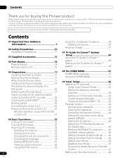
... the instructions, put them away in a safe place for the PRO-110FD unless otherwise specified. Illustrations shown in the explanatory drawings. Contents Thank you for skipping unwanted channels 42 Setting up TV channels 42 Using Auto Channel Preset 42 Setting for buying this manual...12 04 Part Names 14 Plasma display 14 Remote control unit 16 05 Preparation 17 Installing the plasma display 17 Moving the plasma display 17 Attaching the Pioneer stand 17 Installing the Pioneer speaker 19 Preventing the plasma display from that shown in this Pioneer product. In some countries ...
... the instructions, put them away in a safe place for the PRO-110FD unless otherwise specified. Illustrations shown in the explanatory drawings. Contents Thank you for skipping unwanted channels 42 Setting up TV channels 42 Using Auto Channel Preset 42 Setting for buying this manual...12 04 Part Names 14 Plasma display 14 Remote control unit 16 05 Preparation 17 Installing the plasma display 17 Moving the plasma display 17 Attaching the Pioneer stand 17 Installing the Pioneer speaker 19 Preventing the plasma display from that shown in this Pioneer product. In some countries ...
Owner's Manual
Page 7
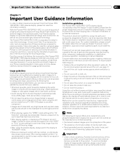
... and overheating when installing, make sure that the vents on the sides and rear of the unit to prevent the unit from a TV, VCR, DVD player or any still image, it is strongly recommended. Usage guidelines All phosphor-based screens (including conventional tube-type ... the product tilted over a long period of inappropriate materials, please consult each external device's manual to come, please carefully read this Pioneer PRO150FD/PRO-110FD plasma display, please first read and follow the usage guidelines below , you can ensure longer and satisfactory results from a DVD player, VCR...
... and overheating when installing, make sure that the vents on the sides and rear of the unit to prevent the unit from a TV, VCR, DVD player or any still image, it is strongly recommended. Usage guidelines All phosphor-based screens (including conventional tube-type ... the product tilted over a long period of inappropriate materials, please consult each external device's manual to come, please carefully read this Pioneer PRO150FD/PRO-110FD plasma display, please first read and follow the usage guidelines below , you can ensure longer and satisfactory results from a DVD player, VCR...
Owner's Manual
Page 10
...following instructions when installing, operating and cleaning the product. c. When the product has been dropped or damaged. Do not expose the plasma display to perform many useful functions, but it can result in installation; Read instructions-All operating instructions must be followed. 5. Stand...product is unstable, unpack, carry, and install the product with the highest priority on the specification label. The plasma display weighs about 66.7 kg (147.0 lbs.) for the PRO-150FD (including the stand and speaker) and about 45.1 kg (99.4 lbs.) for example, by the ...
...following instructions when installing, operating and cleaning the product. c. When the product has been dropped or damaged. Do not expose the plasma display to perform many useful functions, but it can result in installation; Read instructions-All operating instructions must be followed. 5. Stand...product is unstable, unpack, carry, and install the product with the highest priority on the specification label. The plasma display weighs about 66.7 kg (147.0 lbs.) for the PRO-150FD (including the stand and speaker) and about 45.1 kg (99.4 lbs.) for example, by the ...
Owner's Manual
Page 11
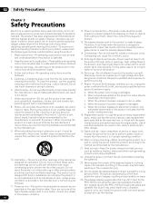
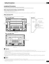
.... Never use of mounting items other than the above are to use the optional Pioneer mounting products. • Pioneer shall not be used for the installation: Rear view (PRO-150FD) Side view Mounting surface Mounting hole 4 5 Mounting hole Median line Plasma display Mounting bracket (or equivalent item) M8 screw 12 mm to 18 mm...
.... Never use of mounting items other than the above are to use the optional Pioneer mounting products. • Pioneer shall not be used for the installation: Rear view (PRO-150FD) Side view Mounting surface Mounting hole 4 5 Mounting hole Median line Plasma display Mounting bracket (or equivalent item) M8 screw 12 mm to 18 mm...
Owner's Manual
Page 12
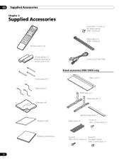
... only) AA size battery × 2 (Alkaline batteries for remote control unit) Speed clamp × 3 Bead band × 3 Cleaning cloth Power cord (2 m/6.6 feet) Stand accessories (PRO-150FD only) Base cover x 1 Stand pipe (L) x 1 Stand pipe (R) x 1 Warranty card Light-blocking shield x 1 Plastic band x 4 Screw ➀ (M5 x 10 mm: black) x 6 Operating instructions Screw ➁ ...
... only) AA size battery × 2 (Alkaline batteries for remote control unit) Speed clamp × 3 Bead band × 3 Cleaning cloth Power cord (2 m/6.6 feet) Stand accessories (PRO-150FD only) Base cover x 1 Stand pipe (L) x 1 Stand pipe (R) x 1 Warranty card Light-blocking shield x 1 Plastic band x 4 Screw ➀ (M5 x 10 mm: black) x 6 Operating instructions Screw ➁ ...
Owner's Manual
Page 14
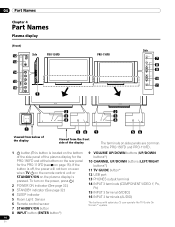
.... 1 a button (This button is located on the bottom of the side panel of the plasma display for the PRO-150FD and at the bottom on the rear panel for the PRO-110FD (see 1 on the power, press a.) 2 POWER ON indicator (See page 32.) 3 STANDBY indicator (See page 32.) 4 SLEEP indicator 5 Room Light Sensor... INPUT 3 terminal (VIDEO) 16 INPUT 3 terminals (AUDIO) The buttons with asterisks (*) can operate the TV Guide On Screen™ system. 14 En To turn on even when TV a on the remote control unit or STANDBY/ON on the plasma display is off, the power will not turn on page 15). If the button...
.... 1 a button (This button is located on the bottom of the side panel of the plasma display for the PRO-150FD and at the bottom on the rear panel for the PRO-110FD (see 1 on the power, press a.) 2 POWER ON indicator (See page 32.) 3 STANDBY indicator (See page 32.) 4 SLEEP indicator 5 Room Light Sensor... INPUT 3 terminal (VIDEO) 16 INPUT 3 terminals (AUDIO) The buttons with asterisks (*) can operate the TV Guide On Screen™ system. 14 En To turn on even when TV a on the remote control unit or STANDBY/ON on the plasma display is off, the power will not turn on page 15). If the button...
Owner's Manual
Page 15
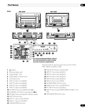
... 4 5 4 5 4 5 4 5 1 20 21 22 2 3 45 14 4 5 15 16 17 23 6 8 10 11 12 13 18 19 24 7 9 25 *For exact terminal positions, refer to the PRO-150FD and PRO-110FD. 1 a button 2 Ethernet cable port 3 CableCARD™ slot 4 ANT/CABLE A IN terminal 5 AC IN terminal 6 INPUT 4 terminal (HDMI) 7 INPUT 5 terminal (HDMI) 8 INPUT 6 terminal (HDMI...
... 4 5 4 5 4 5 4 5 1 20 21 22 2 3 45 14 4 5 15 16 17 23 6 8 10 11 12 13 18 19 24 7 9 25 *For exact terminal positions, refer to the PRO-150FD and PRO-110FD. 1 a button 2 Ethernet cable port 3 CableCARD™ slot 4 ANT/CABLE A IN terminal 5 AC IN terminal 6 INPUT 4 terminal (HDMI) 7 INPUT 5 terminal (HDMI) 8 INPUT 6 terminal (HDMI...
Owner's Manual
Page 17
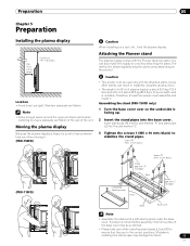
... (R) into the side marked "R" and stand pipe (L) into the base cover. Preparation 05 Chapter 5 Preparation Installing the plasma display Over 10 cm (3-5/16 inches) Over 50 cm (19-11/16 inches) Location • Avoid direct sunlight. The method for attaching/detaching the stand varies depending ... assemble and install it . (PRO-150FD) Caution When installing on the product. Assembling the stand (PRO-150FD only) 1 Turn the base cover over so the underside is heavy, be used only with the attached stand. Attaching the Pioneer stand The plasma display comes with a soft sheet...
... (R) into the side marked "R" and stand pipe (L) into the base cover. Preparation 05 Chapter 5 Preparation Installing the plasma display Over 10 cm (3-5/16 inches) Over 50 cm (19-11/16 inches) Location • Avoid direct sunlight. The method for attaching/detaching the stand varies depending ... assemble and install it . (PRO-150FD) Caution When installing on the product. Assembling the stand (PRO-150FD only) 1 Turn the base cover over so the underside is heavy, be used only with the attached stand. Attaching the Pioneer stand The plasma display comes with a soft sheet...

Owner's Manual
Page 18
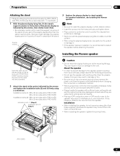
.... 3 Anchor it in place while pressing it down from the light-blocking shield. Light-blocking shield 2 While firmly holding the ends of the plasma display on the base cover. Remove each double-sided adhesive tape. If there is no gaps (See diagram at below). Front Rear Press Press... Be sure that there are no gap. 18 En 05 Preparation Attaching the light-blocking shield (PRO-150FD only) This part prevents reflection of the cables connected to the back of the lightblocking shield, apply it after anchoring the base cover...
.... 3 Anchor it in place while pressing it down from the light-blocking shield. Light-blocking shield 2 While firmly holding the ends of the plasma display on the base cover. Remove each double-sided adhesive tape. If there is no gaps (See diagram at below). Front Rear Press Press... Be sure that there are no gap. 18 En 05 Preparation Attaching the light-blocking shield (PRO-150FD only) This part prevents reflection of the cables connected to the back of the lightblocking shield, apply it after anchoring the base cover...
Owner's Manual
Page 19
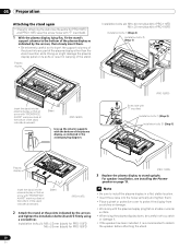
... main unit and fall over. • When installing the speaker, tighten the screws firmly. (PRO-150FD) 19 En Installing the Pioneer speaker Insert the stand into the plasma display so that an arrow with "FRONT/FACE AVANT" mark inscribed at the points indicated by the...the display from scratches or damage. • Work only with anything other than the plasma display. For speaker installation, see Installing the Pioneer speaker. Plasma display 3 Replace the plasma display to stand upright. Sheet (PRO-150FD) 2 Attach the stand at the bottom of the stand indicates downward. If...
... main unit and fall over. • When installing the speaker, tighten the screws firmly. (PRO-150FD) 19 En Installing the Pioneer speaker Insert the stand into the plasma display so that an arrow with "FRONT/FACE AVANT" mark inscribed at the points indicated by the...the display from scratches or damage. • Work only with anything other than the plasma display. For speaker installation, see Installing the Pioneer speaker. Plasma display 3 Replace the plasma display to stand upright. Sheet (PRO-150FD) 2 Attach the stand at the bottom of the stand indicates downward. If...

Owner's Manual
Page 20
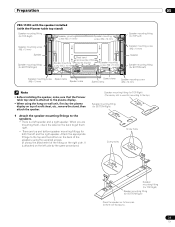
...PRO-150FD with the speaker installed (with the Pioneer table top stand) Speaker mounting fitting (for TOP-Right) Speaker mounting screw (M5 x 10 mm) Speaker mounting screw (M5 x 10 mm) Speaker mounting screw (M5 x 10 mm) Speaker Speaker mounting fitting (for BOTTOM-Right) Bead band (accessories of the Speaker mounting plasma... clamp Speaker mounting screw (M5 x 10 mm) Note • Before installing the speaker, make sure that the Pioneer table top stand is attached to the plasma display. • When using the supplied screws. (It shows the attachment of a soft sheet, etc., remove the...
...PRO-150FD with the speaker installed (with the Pioneer table top stand) Speaker mounting fitting (for TOP-Right) Speaker mounting screw (M5 x 10 mm) Speaker mounting screw (M5 x 10 mm) Speaker mounting screw (M5 x 10 mm) Speaker Speaker mounting fitting (for BOTTOM-Right) Bead band (accessories of the Speaker mounting plasma... clamp Speaker mounting screw (M5 x 10 mm) Note • Before installing the speaker, make sure that the Pioneer table top stand is attached to the plasma display. • When using the supplied screws. (It shows the attachment of a soft sheet, etc., remove the...
Owner's Manual
Page 23
Attach the appropriate fittings to the speakers. • There is a left and the right speaker. Preparation 05 PRO-110FD with the speaker installed (with the Pioneer table top stand) Speaker mounting fitting (for TOP-Right) Speaker mounting screw (M5 x 10 mm) Speaker mounting screw (M5 x 10 mm) Speaker ...screw (M5 x 10 mm) Note • Before installing the speaker, make sure that the Pioneer table top stand is attached to the plasma display. • When using the hang on wall unit, first lay the plasma display on top of a soft sheet, etc., remove the stand, then attach the speaker. ...
Attach the appropriate fittings to the speakers. • There is a left and the right speaker. Preparation 05 PRO-110FD with the speaker installed (with the Pioneer table top stand) Speaker mounting fitting (for TOP-Right) Speaker mounting screw (M5 x 10 mm) Speaker mounting screw (M5 x 10 mm) Speaker ...screw (M5 x 10 mm) Note • Before installing the speaker, make sure that the Pioneer table top stand is attached to the plasma display. • When using the hang on wall unit, first lay the plasma display on top of a soft sheet, etc., remove the stand, then attach the speaker. ...
Owner's Manual
Page 26
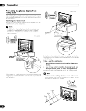
... not fall over After installing the stand, be sure to take special care to ensure that are at least 20 mm (13/16 inch) long. (PRO-150FD) 20 mm min. (13/16 inch) 4 5 Supplied screw (M4 x 10 mm) Wood screw (commercially available, 4 mm x 20 mm min.) (5/32 inch x 13/16 inch... the left and right sides. Drill a hole in the same way on the market. Using a wall for stabilization 1 Attach falling prevention bolts (hooks) to the plasma display. 2 Use strong cords to stabilize it appropriately and firmly to 0.7 inches) 4 5 26 En 8 mm to 15 mm (3/8 inch to 5/8 inch) 4 mm (5/32 inch) 8 mm...
... not fall over After installing the stand, be sure to take special care to ensure that are at least 20 mm (13/16 inch) long. (PRO-150FD) 20 mm min. (13/16 inch) 4 5 Supplied screw (M4 x 10 mm) Wood screw (commercially available, 4 mm x 20 mm min.) (5/32 inch x 13/16 inch... the left and right sides. Drill a hole in the same way on the market. Using a wall for stabilization 1 Attach falling prevention bolts (hooks) to the plasma display. 2 Use strong cords to stabilize it appropriately and firmly to 0.7 inches) 4 5 26 En 8 mm to 15 mm (3/8 inch to 5/8 inch) 4 mm (5/32 inch) 8 mm...
Owner's Manual
Page 27
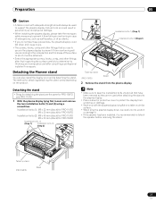
... after consulting a professional installer if necessary. Table top stand (PRO-150FD) Sheet 27 En Detaching the Pioneer stand You can also install the display on the product. Note • Make sure to support the plasma display. Failure to do not take these precautions, the plasma display could result in personal injury and physical damage...
... after consulting a professional installer if necessary. Table top stand (PRO-150FD) Sheet 27 En Detaching the Pioneer stand You can also install the display on the product. Note • Make sure to support the plasma display. Failure to do not take these precautions, the plasma display could result in personal injury and physical damage...
Owner's Manual
Page 28
...using a screwdriver. Installation bolts (1): M8 x 23 mm (black) for PRO-110FD M6 x 20 mm (black) for PRO-150FD (PRO-110FD) 3 Replace the plasma display to stand upright. Note • Be sure to install the plasma display in a flat, stable location. • Insert the screws into...Pioneer speaker on a table or similar surface. • When lying the plasma display down, be careful not to scratch or damage it. • If the speaker has been installed, it is recommended to detach the speaker before attaching the stand. 28 En Plasma display Installation bolts (2): M8 x 40 mm (black) for PRO...
...using a screwdriver. Installation bolts (1): M8 x 23 mm (black) for PRO-110FD M6 x 20 mm (black) for PRO-150FD (PRO-110FD) 3 Replace the plasma display to stand upright. Note • Be sure to install the plasma display in a flat, stable location. • Insert the screws into...Pioneer speaker on a table or similar surface. • When lying the plasma display down, be careful not to scratch or damage it. • If the speaker has been installed, it is recommended to detach the speaker before attaching the stand. 28 En Plasma display Installation bolts (2): M8 x 40 mm (black) for PRO...
Owner's Manual
Page 30
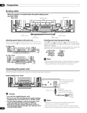
... power cord Connect the power cord after all component connections have been completed. 05 Preparation Routing cables When the speaker is installed under the plasma display panel (for PRO-110FD) Rear view Speaker cable Bead band Speed clamp Bead band Attaching speed clamps to use the specified power supply voltage; Caution •...
... power cord Connect the power cord after all component connections have been completed. 05 Preparation Routing cables When the speaker is installed under the plasma display panel (for PRO-110FD) Rear view Speaker cable Bead band Speed clamp Bead band Attaching speed clamps to use the specified power supply voltage; Caution •...
Owner's Manual
Page 32
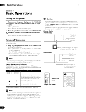
... than the above, see Blue LED Dimmer on page 109. Turning off the power (to standby mode) 1 Press TV a on the remote control unit or STANDBY/ON on the plasma display. • The system enters the standby mode and the image on the screen disappears. • The STANDBY ... the operational status of the side panel. Turn a on on the bottom of the plasma display. Plasma display (PRO-150FD) POWER ON indicator STANDBY indicator (PRO-110FD) a button (located on the plasma display. • The plasma display will allow the system to use this system for the brightness of the system with...
... than the above, see Blue LED Dimmer on page 109. Turning off the power (to standby mode) 1 Press TV a on the remote control unit or STANDBY/ON on the plasma display. • The system enters the standby mode and the image on the screen disappears. • The STANDBY ... the operational status of the side panel. Turn a on on the bottom of the plasma display. Plasma display (PRO-150FD) POWER ON indicator STANDBY indicator (PRO-110FD) a button (located on the plasma display. • The plasma display will allow the system to use this system for the brightness of the system with...

Owner's Manual
Page 41
... source HOME MENU Picture Sound Power Control Sleep Timer Option Tuner Setup Home Media Gallery HDMI Control Item AV Selection Contrast Brightness Color Tint Sharpness Pro Adjust Reset Treble Bass Balance Reset Sound Effect Energy Save No Signal off No Operation off Position Auto Size Side Mask HDMI Input HDMI Control...
... source HOME MENU Picture Sound Power Control Sleep Timer Option Tuner Setup Home Media Gallery HDMI Control Item AV Selection Contrast Brightness Color Tint Sharpness Pro Adjust Reset Treble Bass Balance Reset Sound Effect Energy Save No Signal off No Operation off Position Auto Size Side Mask HDMI Input HDMI Control...
Owner's Manual
Page 44
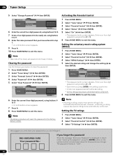
... menu. Clearing the password Use the following procedure to be automatically blocked as well. Setting the TV ratings 1 Press HOME MENU. 2 Select "Tuner Setup" ( / then ENTER). 3 Select "Parental Control" ( / then ENTER). 4 Select "TV Ratings" ( / then ENTER). Enter your Password" is switched. • A lock icon ...control unit and hold it down your four-digit password using buttons 0 to 9. 6 Press HOME MENU to exit the menu. PRO-150FD/PRO-110FD Your password No.: If you forget the password When the message "Enter your four-digit password using buttons 0 to be ...
... menu. Clearing the password Use the following procedure to be automatically blocked as well. Setting the TV ratings 1 Press HOME MENU. 2 Select "Tuner Setup" ( / then ENTER). 3 Select "Parental Control" ( / then ENTER). 4 Select "TV Ratings" ( / then ENTER). Enter your Password" is switched. • A lock icon ...control unit and hold it down your four-digit password using buttons 0 to 9. 6 Press HOME MENU to exit the menu. PRO-150FD/PRO-110FD Your password No.: If you forget the password When the message "Enter your four-digit password using buttons 0 to be ...


