

Owner's Manual
Page 5
... PHASE (Automatic Adjust 39 Adjusting Screen POSITION, CLOCK, and PHASE (Manual Adjust 39 Other Operations 42 Setting the PURECINEMA Mode 42 Setting Screen Center Brightness Compensation (BRT. Contents Contents Safety Precautions i Before Proceeding 2 How to operate the Plasma Display properly. PIONEER cannot assume liabilities for Dealers: After installation, be sure to deliver this...
... PHASE (Automatic Adjust 39 Adjusting Screen POSITION, CLOCK, and PHASE (Manual Adjust 39 Other Operations 42 Setting the PURECINEMA Mode 42 Setting Screen Center Brightness Compensation (BRT. Contents Contents Safety Precautions i Before Proceeding 2 How to operate the Plasma Display properly. PIONEER cannot assume liabilities for Dealers: After installation, be sure to deliver this...
Owner's Manual
Page 6
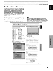
... with the plasma monitor and remote control unit, as shown: Example of PRO-1010HD Menu Display: S TA N D A R D PICTURE SCREEN SETUP CONTRAST BRIGHTNESS COLOR TINT SHARPNESS MPEG NR DNR CTI :0 :0 :0 :0 :0 : MID : MID : ON INPUT1 OPTION PICTURE RESET SET ENTER MENU EXIT Example of PRO-810HD Menu Display: S TA N D A R D PICTURE SCREEN CONTRAST BRIGHTNESS COLOR TINT SHARPNESS...
... with the plasma monitor and remote control unit, as shown: Example of PRO-1010HD Menu Display: S TA N D A R D PICTURE SCREEN SETUP CONTRAST BRIGHTNESS COLOR TINT SHARPNESS MPEG NR DNR CTI :0 :0 :0 :0 :0 : MID : MID : ON INPUT1 OPTION PICTURE RESET SET ENTER MENU EXIT Example of PRO-810HD Menu Display: S TA N D A R D PICTURE SCREEN CONTRAST BRIGHTNESS COLOR TINT SHARPNESS...
Owner's Manual
Page 7
... operating order. Colors become weaker Colors become stronger TINT Skin tones become purplish Skin tones become greenish SHARPNESS ... Each time you press the 2/3 buttons, the setting changes as follows: 3 OFF 2 3 LOW 2 3 HIGH 2 3 MID 2 ¶ As you brighten color contour as follows: 3 OFF 2... 2/3 buttons to adjust picture quality to those buttons found on the remote control unit, the commands can save picture adjustment setting values for the section "PICTURE adjustment". These Operating Instructions will be considered typical images; CTI is operating. ¶ OFF...
... operating order. Colors become weaker Colors become stronger TINT Skin tones become purplish Skin tones become greenish SHARPNESS ... Each time you press the 2/3 buttons, the setting changes as follows: 3 OFF 2 3 LOW 2 3 HIGH 2 3 MID 2 ¶ As you brighten color contour as follows: 3 OFF 2... 2/3 buttons to adjust picture quality to those buttons found on the remote control unit, the commands can save picture adjustment setting values for the section "PICTURE adjustment". These Operating Instructions will be considered typical images; CTI is operating. ¶ OFF...
Owner's Manual
Page 9
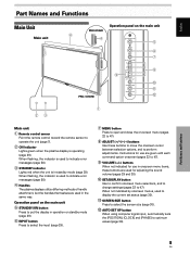
... (pages 22 to 47). 9 VOLUME (+/-) buttons When not indicated for adjusting the sound volume (pages 29 and 30). 0 SET/DISPLAY button Use to confirm onscreen menu selections, and to change settings (pages 22 to operate the unit (page 7). 2 ON indicator Lights green when the plasma display is in the same way...standby mode (page 29). 6 INPUT button Press to select the input (page 29). 7 MENU button Press to open and close the on the main unit PRO-810HD 4 4 5 6 7 8 9 0 = PRO-1010HD 1 23 Main unit 1 Remote control sensor Point the remote control toward the remote sensor to 47).
... (pages 22 to 47). 9 VOLUME (+/-) buttons When not indicated for adjusting the sound volume (pages 29 and 30). 0 SET/DISPLAY button Use to confirm onscreen menu selections, and to change settings (pages 22 to operate the unit (page 7). 2 ON indicator Lights green when the plasma display is in the same way...standby mode (page 29). 6 INPUT button Press to select the input (page 29). 7 MENU button Press to open and close the on the main unit PRO-810HD 4 4 5 6 7 8 9 0 = PRO-1010HD 1 23 Main unit 1 Remote control sensor Point the remote control toward the remote sensor to 47).

Owner's Manual
Page 10
...position of subscreen (page 32). @ VOLUME (+/-) buttons Use to adjust the volume (pages 29 and 30). PIP SHIFT button When using computer signal input, automatically sets the [POSITION], [CLOCK] and [PHASE] to optimum values (page 39). - STANDBY/ON button Press to put the unit in operation or standby mode (... (page 32). 8 SPLIT button Press to switch to multi-screen display (page 32). 9 MUTING button Press to mute the volume (page 30). 0 AUTO SET UP button When using PinP mode with multi-screen display, use this button to wear out, the operable distance will gradually become shorter.
...position of subscreen (page 32). @ VOLUME (+/-) buttons Use to adjust the volume (pages 29 and 30). PIP SHIFT button When using computer signal input, automatically sets the [POSITION], [CLOCK] and [PHASE] to optimum values (page 39). - STANDBY/ON button Press to put the unit in operation or standby mode (... (page 32). 8 SPLIT button Press to switch to multi-screen display (page 32). 9 MUTING button Press to mute the volume (page 30). 0 AUTO SET UP button When using PinP mode with multi-screen display, use this button to wear out, the operable distance will gradually become shorter.

Owner's Manual
Page 13
6 HDMI (INPUT1) (HDMI jack) For connection of components that have a digital video output terminal such as a digital set top box, DVD player, etc. Note The left speaker. Note The video signal will not be output from the connected component (pages 12 to 15).... SPEAKER (L) terminal For connection of this display is not compatible with the plasma display; Make sure that have a digital video output terminal such as a digital set top box, DVD player, etc. Part Names and Functions @ AUDIO R/L (INPUT3/4) (RCA Pin jacks) Use to obtain sound when INPUT5 is selected. Connect ...
6 HDMI (INPUT1) (HDMI jack) For connection of components that have a digital video output terminal such as a digital set top box, DVD player, etc. Note The left speaker. Note The video signal will not be output from the connected component (pages 12 to 15).... SPEAKER (L) terminal For connection of this display is not compatible with the plasma display; Make sure that have a digital video output terminal such as a digital set top box, DVD player, etc. Part Names and Functions @ AUDIO R/L (INPUT3/4) (RCA Pin jacks) Use to obtain sound when INPUT5 is selected. Connect ...

Owner's Manual
Page 19
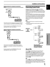
... connected component. Notes ÷ When making composite SYNC connections, do not connect anything to INPUT1 (HDMI) Connect an AV component with a digital video output (digital set top box, DVD player, etc.) compatible with HDCP (High-bandwidth Digital Content Protection). When connecting to ANALOG RGB IN (INPUT1) ANALOG RGB IN D-Sub IINNPPUUTT11...
... connected component. Notes ÷ When making composite SYNC connections, do not connect anything to INPUT1 (HDMI) Connect an AV component with a digital video output (digital set top box, DVD player, etc.) compatible with HDCP (High-bandwidth Digital Content Protection). When connecting to ANALOG RGB IN (INPUT1) ANALOG RGB IN D-Sub IINNPPUUTT11...

Owner's Manual
Page 20
English Installation and Connections Connection to INPUT2 Connect an AV component with a digital video output (digital set top box, DVD player, etc.) compatible with a digital video output After connection is made, on-screen setup is necessary to match the connected component. Note A ...
English Installation and Connections Connection to INPUT2 Connect an AV component with a digital video output (digital set top box, DVD player, etc.) compatible with a digital video output After connection is made, on-screen setup is necessary to match the connected component. Note A ...

Owner's Manual
Page 21
... (525i) 480p (525p) Video signal format Component RGB Digital Composite S-Video Component RGB Digital Component RGB Digital Jacks where connection is compatible with the DTV set top box output signals that this display is possible INPUT1 INPUT1 INPUT2 INPUT3 INPUT4 INPUT5 (D-sub) (HDMI) Installation and Connections 17 EN The...
... (525i) 480p (525p) Video signal format Component RGB Digital Composite S-Video Component RGB Digital Component RGB Digital Jacks where connection is compatible with the DTV set top box output signals that this display is possible INPUT1 INPUT1 INPUT2 INPUT3 INPUT4 INPUT5 (D-sub) (HDMI) Installation and Connections 17 EN The...

Owner's Manual
Page 22
... R L The audio line for INPUT3 and INPUT4. The following the accompanying connection instructions. 12 mm Twist exposed wire strands together. Note When using AUDIO INPUT2, set AUDIO to the open position, and insert the wire. Installation and Connections 18 EN Making connections to malfunction or stop. Audio connection for component connected... (L/R) Pin jacks (L/R)*2 Pin jacks (L/R)*2 Pin jacks (L/R) Sound output Sound of INPUT1 can be connected to the video input selection. Note When using HDMI analog audio, set the AUDIO to ANALOG (or AUTO) (Please see page 27).
... R L The audio line for INPUT3 and INPUT4. The following the accompanying connection instructions. 12 mm Twist exposed wire strands together. Note When using AUDIO INPUT2, set AUDIO to the open position, and insert the wire. Installation and Connections 18 EN Making connections to malfunction or stop. Audio connection for component connected... (L/R) Pin jacks (L/R)*2 Pin jacks (L/R)*2 Pin jacks (L/R) Sound output Sound of INPUT1 can be connected to the video input selection. Note When using HDMI analog audio, set the AUDIO to ANALOG (or AUTO) (Please see page 27).
Owner's Manual
Page 23
...EN Sound is possible for a component connected to either INPUT3 or INPUT4. You can be sure to perform SR+ related function settings on your PIONEER AV receiver. CONTROL IN SR OUT OUT CONTROL CONTROL IN SR OUT Installation and Connections CONTROL IN SR OUT Audio input to...not accept commands from the SPEAKER (L/R) terminals according to the video input selection. For more information, see the user's manual for the PIONEER AV receiver supporting SR+. English Audio connection for component connected to INPUT5 INPUT5 AUDIO R L The audio line for the component connected to...
...EN Sound is possible for a component connected to either INPUT3 or INPUT4. You can be sure to perform SR+ related function settings on your PIONEER AV receiver. CONTROL IN SR OUT OUT CONTROL CONTROL IN SR OUT Installation and Connections CONTROL IN SR OUT Audio input to...not accept commands from the SPEAKER (L/R) terminals according to the video input selection. For more information, see the user's manual for the PIONEER AV receiver supporting SR+. English Audio connection for component connected to INPUT5 INPUT5 AUDIO R L The audio line for the component connected to...

Owner's Manual
Page 26
... on the front panel will light red. 2 Press the STANDBY/ON button to select [OPTION]. The selected language will be set in memory, and the screen will return to that shown in the following order: 3 ENGLISH 2 3 FRANÇAIS 2 3 ESPAÑ...ENGLISH : STANDARD : OFF : DISABLE : OFF : ON : D-SUB : OFF System Settings MENU 5/∞ STANDBY/ ON 2/3 SET MENU 2/3 SET 5/∞ Display operating panel Remote control unit 1 Set the rear panel MAIN POWER switch to select [LANGUAGE], then press the SET button. S TA N D A R D PICTURE SCREEN SETUP CONTRAST BRIGHTNESS COLOR TINT SHARPNESS ...
... on the front panel will light red. 2 Press the STANDBY/ON button to select [OPTION]. The selected language will be set in memory, and the screen will return to that shown in the following order: 3 ENGLISH 2 3 FRANÇAIS 2 3 ESPAÑ...ENGLISH : STANDARD : OFF : DISABLE : OFF : ON : D-SUB : OFF System Settings MENU 5/∞ STANDBY/ ON 2/3 SET MENU 2/3 SET 5/∞ Display operating panel Remote control unit 1 Set the rear panel MAIN POWER switch to select [LANGUAGE], then press the SET button. S TA N D A R D PICTURE SCREEN SETUP CONTRAST BRIGHTNESS COLOR TINT SHARPNESS ...
Owner's Manual
Page 27
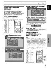
...D A R D PICTURE SCREEN SETUP CONTRAST BRIGHTNESS COLOR TINT SHARPNESS MPEG NR DNR CTI :0 :0 :0 :0 :0 : MID : MID : ON INPUT1 OPTION PICTURE RESET SET ENTER MENU EXIT 2 Use the 2/3 buttons to display the menu screen. S TA N D A R D INPUT1 PICTURE SCREEN SETUP OPTION LANGUAGE ENERGY SAVE POWER MANAGEMENT ...MASK CONTROL INPUT1 SELECT SR+ MODE : ENGLISH : STANDARD : OFF : DISABLE : OFF : ON : D-SUB : OFF SET ENTER MENU EXIT System Settings 3 Use the 5/∞ buttons to select the desired INPUT. Each time you can use . Follow the procedure described below ...
...D A R D PICTURE SCREEN SETUP CONTRAST BRIGHTNESS COLOR TINT SHARPNESS MPEG NR DNR CTI :0 :0 :0 :0 :0 : MID : MID : ON INPUT1 OPTION PICTURE RESET SET ENTER MENU EXIT 2 Use the 2/3 buttons to display the menu screen. S TA N D A R D INPUT1 PICTURE SCREEN SETUP OPTION LANGUAGE ENERGY SAVE POWER MANAGEMENT ...MASK CONTROL INPUT1 SELECT SR+ MODE : ENGLISH : STANDARD : OFF : DISABLE : OFF : ON : D-SUB : OFF SET ENTER MENU EXIT System Settings 3 Use the 5/∞ buttons to select the desired INPUT. Each time you can use . Follow the procedure described below ...
Owner's Manual
Page 28
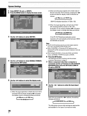
...POSITION SIGNAL FORMAT COLOR DECODING HDMI INPUT BRT. ENHANCE : OFF : AUTO : 480p : COMPONENT : ON 8 Use the 2/3 buttons to select [SETUP]. COLOR DECODING SET S E T : COMPONENT MENU E X I T 1 When the input signal has a refresh rate of 31.5 kHz horizontal / 60 Hz vertical, pressing 2/3 ...] indicates resolution of 1280 x 720. 3 When the input signal has a refresh rate of connections made. Notes ÷ The [PC AUTO] setting supports automatic signal selection only when using RGB separate SYNC inputs. ÷ When G ON SYNC or Composite SYNC signals are appropriate and available for...
...POSITION SIGNAL FORMAT COLOR DECODING HDMI INPUT BRT. ENHANCE : OFF : AUTO : 480p : COMPONENT : ON 8 Use the 2/3 buttons to select [SETUP]. COLOR DECODING SET S E T : COMPONENT MENU E X I T 1 When the input signal has a refresh rate of 31.5 kHz horizontal / 60 Hz vertical, pressing 2/3 ...] indicates resolution of 1280 x 720. 3 When the input signal has a refresh rate of connections made. Notes ÷ The [PC AUTO] setting supports automatic signal selection only when using RGB separate SYNC inputs. ÷ When G ON SYNC or Composite SYNC signals are appropriate and available for...
Owner's Manual
Page 29
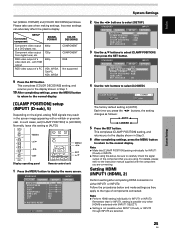
... A R D PICTURE SCREEN SETUP CONTRAST BRIGHTNESS COLOR TINT SHARPNESS MPEG NR DNR CTI :0 :0 :0 :0 :0 : MID : MID : ON INPUT1 OPTION PICTURE RESET SET ENTER MENU EXIT System Settings 2 Use the 2/3 buttons to [LOCKED]. S TA N D A R D PICTURE SCREEN SETUP PURECINEMA : OFF CLAMP POSITION : AUTO SIGNAL FORMAT : 480p COLOR ...] setup (INPUT1 (D-sub), 5) Depending on the signal, analog RGB signals may result in Step 3. 6 After completing settings, press the MENU button to return to the normal display. Remember that you are connecting. Connected component SETUP SIGNAL FORMAT ...
... A R D PICTURE SCREEN SETUP CONTRAST BRIGHTNESS COLOR TINT SHARPNESS MPEG NR DNR CTI :0 :0 :0 :0 :0 : MID : MID : ON INPUT1 OPTION PICTURE RESET SET ENTER MENU EXIT System Settings 2 Use the 2/3 buttons to [LOCKED]. S TA N D A R D PICTURE SCREEN SETUP PURECINEMA : OFF CLAMP POSITION : AUTO SIGNAL FORMAT : 480p COLOR ...] setup (INPUT1 (D-sub), 5) Depending on the signal, analog RGB signals may result in Step 3. 6 After completing settings, press the MENU button to return to the normal display. Remember that you are connecting. Connected component SETUP SIGNAL FORMAT ...

Owner's Manual
Page 30
...COLOR2, COLOR3 or COLOR4 manually in the picture when accepts RGB signals. ENHANCE : OFF : : : : ON OPTION SET ENTER MENU EXIT 3 Use the 5/∞ buttons to select [SET UP]. S TA N D A R D INPUT1 PICTURE SCREEN SETUP PURECINEMA : OFF CLAMP POSITION : SIGNAL FORMAT :..., automatic switching may not occur properly with the actual signal input. 6 Press the SET button. English System Settings PICTURE SELECT This function allows you press the 2/3 buttons, the setting changes as follows: AUTO COLOR1 COLOR4 COLOR3 COLOR2 AUTO: Automatically identifies input video signals....
...COLOR2, COLOR3 or COLOR4 manually in the picture when accepts RGB signals. ENHANCE : OFF : : : : ON OPTION SET ENTER MENU EXIT 3 Use the 5/∞ buttons to select [SET UP]. S TA N D A R D INPUT1 PICTURE SCREEN SETUP PURECINEMA : OFF CLAMP POSITION : SIGNAL FORMAT :..., automatic switching may not occur properly with the actual signal input. 6 Press the SET button. English System Settings PICTURE SELECT This function allows you press the 2/3 buttons, the setting changes as follows: AUTO COLOR1 COLOR4 COLOR3 COLOR2 AUTO: Automatically identifies input video signals....

Owner's Manual
Page 31
...menu screen. English AUDIO This function allows you press the 2/3 buttons, the setting changes as follows: AUTO ANALOG DIGITAL AUTO: Automatically identifies input audio signals. In this unit to connect another Pioneer product (Refer to page 19 for connection details). 1 Press the MENU button ...to select [AUDIO] setting. Each time you to switch the audio signal to automatic or manual when inputting...
...menu screen. English AUDIO This function allows you press the 2/3 buttons, the setting changes as follows: AUTO ANALOG DIGITAL AUTO: Automatically identifies input audio signals. In this unit to connect another Pioneer product (Refer to page 19 for connection details). 1 Press the MENU button ...to select [AUDIO] setting. Each time you to switch the audio signal to automatic or manual when inputting...

Owner's Manual
Page 32
...+ MODE : ENGLISH : STANDARD : OFF : DISABLE : OFF : ON : D-SUB : OFF SET ENTER MENU EXIT 3 Use the 5/∞ buttons to select [SR+MODE]. System Settings 28 EN SR+MODE SET S E T : ON MENU E X I T The factory setting is effective for all inputs. You can use the CONTROL OUT jack. ÷ ON ...... S... ON INPUT1 SELECT : D-SUB SR+ MODE : OFF SET ENTER MENU EXIT 4 Use the 2/3 buttons to select [SR+MODE], then press the SET button. You cannot use the CONTROL OUT jack. 5 Press the SET button. Note SR+MODE setting is not related to the normal display. Each time you ...
...+ MODE : ENGLISH : STANDARD : OFF : DISABLE : OFF : ON : D-SUB : OFF SET ENTER MENU EXIT 3 Use the 5/∞ buttons to select [SR+MODE]. System Settings 28 EN SR+MODE SET S E T : ON MENU E X I T The factory setting is effective for all inputs. You can use the CONTROL OUT jack. ÷ ON ...... S... ON INPUT1 SELECT : D-SUB SR+ MODE : OFF SET ENTER MENU EXIT 4 Use the 2/3 buttons to select [SR+MODE], then press the SET button. You cannot use the CONTROL OUT jack. 5 Press the SET button. Note SR+MODE setting is not related to the normal display. Each time you ...
Owner's Manual
Page 33
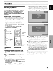
...and off presently. The ON indicator on the front panel will turn off , put the display in the section "System Settings" starting on page 10. • Set up the on-screen menu to input signals from components connected to turn the power ON. If no connections are made ... and how to select connected components. SUB CAUTION OUT OF RANGE fH : 75.7kHz fV :120.0Hz D - Display operating panel Remote control unit VOLUME [+/-] 1 Set the rear panel MAIN POWER switch to OFF. Outlined on the following message will be displayed: INPUT1 S TA N D A R D CAUTION UNSUPPORTED SIGNAL fH : ...
...and off presently. The ON indicator on the front panel will turn off , put the display in the section "System Settings" starting on page 10. • Set up the on-screen menu to input signals from components connected to turn the power ON. If no connections are made ... and how to select connected components. SUB CAUTION OUT OF RANGE fH : 75.7kHz fV :120.0Hz D - Display operating panel Remote control unit VOLUME [+/-] 1 Set the rear panel MAIN POWER switch to OFF. Outlined on the following message will be displayed: INPUT1 S TA N D A R D CAUTION UNSUPPORTED SIGNAL fH : ...
Owner's Manual
Page 35
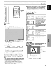
.... FULL 2 Press the SCREEN SIZE button again in the SCREEN SIZE mode indications displayed at the bottom right of authors protected under copyright law. The setting changes as follows: During video signal input 3 WIDE 3 4:3 CINEMA 2 3 FULL ZOOM 2 During PC signal input 3 DOT BY DOT FULL 2 3 ...image. 4:3 Suitable for viewing VistaVision cinema sizes. 1 DOT BY DOT The input signal and the screen maintain a dot to the source. [PRO-1010HD] A 480 lines 768 lines 640 dots 1280 dots (Illustration shows 640 x 480 input.) 31 EN Operation English ZOOM CINEMA Mainly suitable for ...
.... FULL 2 Press the SCREEN SIZE button again in the SCREEN SIZE mode indications displayed at the bottom right of authors protected under copyright law. The setting changes as follows: During video signal input 3 WIDE 3 4:3 CINEMA 2 3 FULL ZOOM 2 During PC signal input 3 DOT BY DOT FULL 2 3 ...image. 4:3 Suitable for viewing VistaVision cinema sizes. 1 DOT BY DOT The input signal and the screen maintain a dot to the source. [PRO-1010HD] A 480 lines 768 lines 640 dots 1280 dots (Illustration shows 640 x 480 input.) 31 EN Operation English ZOOM CINEMA Mainly suitable for ...


