
Operating Instructions
Page 12
... sensor Point the remote control toward the remote sensor to operate the unit (page 8). 3 STANDBY/ON indicator This indicator is red during standby mode, and turns to indicate error messages (page 33).
... sensor Point the remote control toward the remote sensor to operate the unit (page 8). 3 STANDBY/ON indicator This indicator is red during standby mode, and turns to indicate error messages (page 33).
Operating Instructions
Page 21
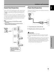
...jack on this may cause fire or electric shock. ÷ For the plasma display, a three-core power cord with a ground terminal is turned off when making control cord connections. English Français Installation and Connections Control Cord Connection When control cord connections are monaural cables with a .... Point the remote control unit of the connected component at the remote control sensor on another unit, the remote sensor of connected PIONEER components that bear the Î logo mark is done through the remote sensor on this unit. 2 Plug the power cord into a power ...
...jack on this may cause fire or electric shock. ÷ For the plasma display, a three-core power cord with a ground terminal is turned off when making control cord connections. English Français Installation and Connections Control Cord Connection When control cord connections are monaural cables with a .... Point the remote control unit of the connected component at the remote control sensor on another unit, the remote sensor of connected PIONEER components that bear the Î logo mark is done through the remote sensor on this unit. 2 Plug the power cord into a power ...

Operating Instructions
Page 23
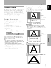
...input signals, screen resolution will cause the screen resolution to be displayed). 1 Switch MAIN POWER on the connection panel to the on position to turn on -screen setup is completed, press MENU to exit the menu screen. MAIN MENU PICTURE SCREEN CONT RAST BR I NG : VGA SELECT ...UP INPUT1 OPTION RE S ET SELECT SET ENTER MENU EXIT 5 Press 2/3 to put the unit in the operation mode. L EVEL G. The STANDBY/ON indicator turns green. 3 Select INPUT1 or INPUT2. 4 Press MENU to display the menu screen. R. Setting Up the System English Français Setting Up the System ...
...input signals, screen resolution will cause the screen resolution to be displayed). 1 Switch MAIN POWER on the connection panel to the on position to turn on -screen setup is completed, press MENU to exit the menu screen. MAIN MENU PICTURE SCREEN CONT RAST BR I NG : VGA SELECT ...UP INPUT1 OPTION RE S ET SELECT SET ENTER MENU EXIT 5 Press 2/3 to put the unit in the operation mode. L EVEL G. The STANDBY/ON indicator turns green. 3 Select INPUT1 or INPUT2. 4 Press MENU to display the menu screen. R. Setting Up the System English Français Setting Up the System ...

Operating Instructions
Page 25
...STANDBY/ON indicator is not necessary. 3 Press INPUT on position to light for a long time. Doing so may continue to turn off . The STANDBY/ON indicator turns green. English Operations Selecting an Input Source This section explains the basic operation of this unit in standby mode. If no ...known as follows. 3 INPUT1 INPUT2 2 • When the menu screen is a result of the picture on page 17. The STANDBY/ON indicator will turn the main power off presently. CAUTION Please do not leave the same picture displayed on the screen for a short while even after the main power...
...STANDBY/ON indicator is not necessary. 3 Press INPUT on position to light for a long time. Doing so may continue to turn off . The STANDBY/ON indicator turns green. English Operations Selecting an Input Source This section explains the basic operation of this unit in standby mode. If no ...known as follows. 3 INPUT1 INPUT2 2 • When the menu screen is a result of the picture on page 17. The STANDBY/ON indicator will turn the main power off presently. CAUTION Please do not leave the same picture displayed on the screen for a short while even after the main power...
Operating Instructions
Page 27
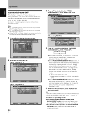
...] 3 DOT BY DOT 3 4:3 PARTIAL 2 FULL 2 [PDP-433CMX] 3 DOT BY DOT 3 4:3 FULL 2 Consult the table Computer Signal Formats Supported (pages 35 and 36) for information regarding screen sizes supported by each time the power is turned on a wide screen, a portion of the picture may violate the rights of...21 En Operations For optimal viewing, we recommend that you make use of them with a widescreen aspect ratio of a picture on the PDP-433CMX. Although these modes are selected, the display position is our hope that the image displayed will appear more oblong than the original input...
...] 3 DOT BY DOT 3 4:3 PARTIAL 2 FULL 2 [PDP-433CMX] 3 DOT BY DOT 3 4:3 FULL 2 Consult the table Computer Signal Formats Supported (pages 35 and 36) for information regarding screen sizes supported by each time the power is turned on a wide screen, a portion of the picture may violate the rights of...21 En Operations For optimal viewing, we recommend that you make use of them with a widescreen aspect ratio of a picture on the PDP-433CMX. Although these modes are selected, the display position is our hope that the image displayed will appear more oblong than the original input...
Operating Instructions
Page 30
... OFF functions must be set individually for each input (INPUT 1 or INPUT 2). Power consumption about 1W *2. E NHANCE V. Except when input signal is selected. ÷ Always turn off the plasma display's main power switch when not using INPUT 2] MAIN MENU INPUT2 PICTURE SCREEN SET UP OPTION I NPUT L ABEL : I NPUT 2 A UTO POWE R OF...
... OFF functions must be set individually for each input (INPUT 1 or INPUT 2). Power consumption about 1W *2. E NHANCE V. Except when input signal is selected. ÷ Always turn off the plasma display's main power switch when not using INPUT 2] MAIN MENU INPUT2 PICTURE SCREEN SET UP OPTION I NPUT L ABEL : I NPUT 2 A UTO POWE R OF...
Operating Instructions
Page 37
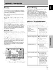
...plug from the display or remote control unit. Wipe the display and remote control gently with a hard object. Vents Illustration depicts PDP-503CMX model. About the self diagnosis mode Messages appear on pages 35 - 36 and set the vacuum cleaner to its weakest ... cloth. After message confirmation, check the condition of paint from its outlet, and consult a Pioneer service center or your dealer. 31 En WARNING FAN FAILURE ¶ Cooling fan has malfunctioned. Immediately turn off main power (page 9). ¶ Is ambient temperature too high? ¶ Remove any...
...plug from the display or remote control unit. Wipe the display and remote control gently with a hard object. Vents Illustration depicts PDP-503CMX model. About the self diagnosis mode Messages appear on pages 35 - 36 and set the vacuum cleaner to its weakest ... cloth. After message confirmation, check the condition of paint from its outlet, and consult a Pioneer service center or your dealer. 31 En WARNING FAN FAILURE ¶ Cooling fan has malfunctioned. Immediately turn off main power (page 9). ¶ Is ambient temperature too high? ¶ Remove any...

Operating Instructions
Page 38
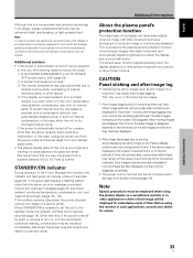
...). • Is a plug connected to the CONTROL IN connector? When a plug is connected to the CONTROL IN connector, the signal from that is suddenly turned off. • No picture Possible Solution • Is the power cord disconnected? (page 15) • Has the MAIN POWER switch been switched on?... may appear to be losing their intensity. Not a malfunction. • Fan is still no improvement, this case, operate the unit after first turning the MAIN POWER ON/OFF, or unplugging the power cord and re-plugging it in accordance with ambient conditions. Not a malfunction. 32 En Additional...
...). • Is a plug connected to the CONTROL IN connector? When a plug is connected to the CONTROL IN connector, the signal from that is suddenly turned off. • No picture Possible Solution • Is the power cord disconnected? (page 15) • Has the MAIN POWER switch been switched on?... may appear to be losing their intensity. Not a malfunction. • Fan is still no improvement, this case, operate the unit after first turning the MAIN POWER ON/OFF, or unplugging the power cord and re-plugging it in accordance with ambient conditions. Not a malfunction. 32 En Additional...
Operating Instructions
Page 39
...The power control function can be displayed for extended periods of this display will change in accordance with a cooling fan designed to turn on the luminance of about three minutes. The screen-saver function begins operating when the display detects no or little screen movement for... temperature has risen abnormally due to blocked cooling vents, overheating of internal electronic parts, or other than this, if the power turns off and change speed automatically in accordance with ambient temperature conditions (the fan sound will deteriorate slightly when an image with very high...
...The power control function can be displayed for extended periods of this display will change in accordance with a cooling fan designed to turn on the luminance of about three minutes. The screen-saver function begins operating when the display detects no or little screen movement for... temperature has risen abnormally due to blocked cooling vents, overheating of internal electronic parts, or other than this, if the power turns off and change speed automatically in accordance with ambient temperature conditions (the fan sound will deteriorate slightly when an image with very high...