Owner's Manual
Page 2
Contents Before you start Information to User 3 After-sales service for Pioneer products 3 Visit our website 3 Before connecting/installing the amplifier 4 Setting the Unit What's what 5 Setting gain properly 5 Connecting the units Connection diagram 7 Before...bridged mode 8 About suitable specification of speaker 8 Connecting the speakers 8 Connections when using the RCA input jack 10 Connections when using the speaker input wire 10 Connecting the power terminal 11 Connecting the speaker output terminals 12 Installation Before installing the amplifier 13 Example of installation on the floor mat...
Contents Before you start Information to User 3 After-sales service for Pioneer products 3 Visit our website 3 Before connecting/installing the amplifier 4 Setting the Unit What's what 5 Setting gain properly 5 Connecting the units Connection diagram 7 Before...bridged mode 8 About suitable specification of speaker 8 Connecting the speakers 8 Connections when using the RCA input jack 10 Connections when using the speaker input wire 10 Connecting the power terminal 11 Connecting the speaker output terminals 12 Installation Before installing the amplifier 13 Example of installation on the floor mat...
Owner's Manual
Page 4
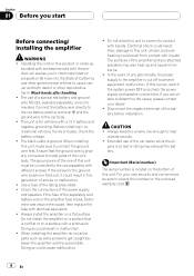
... smoke or malfunction. ! The black cable is located on a flat surface. Do not install the amplifier on a surface that the ground wire is at rest or idling may also heat up and cause minor burns. ! Disconnect the negative terminal of the amplifier and any abnormality,... Electrical shock could result in recreational vehicles, trucks or buses, check the battery voltage. ! Also, damage to this unit to connect the ground wire first. If this unit, make sure to come into contact with identical equivalent. ! If you start Before connecting/ installing the amplifier WARNING ! ...
... smoke or malfunction. ! The black cable is located on a flat surface. Do not install the amplifier on a surface that the ground wire is at rest or idling may also heat up and cause minor burns. ! Disconnect the negative terminal of the amplifier and any abnormality,... Electrical shock could result in recreational vehicles, trucks or buses, check the battery voltage. ! Also, damage to this unit to connect the ground wire first. If this unit, make sure to come into contact with identical equivalent. ! If you start Before connecting/ installing the amplifier WARNING ! ...
Owner's Manual
Page 7
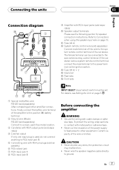
...The female terminal can be set. If the car stereo lacks a system remote control terminal, connect the male terminal to RCA input jack B. 5 Connecting wire with RCA pin plugs (sold separately) 6 RCA output jack 7 RCA input jack A 8 RCA input jack B Before connecting the amplifier WARNING ! For...separately) a Speaker output terminals Please see Setting the Unit on page 10. Current capacity of the amplifier to the positive (+) battery terminal. 2 Ground wire (Black) RD-223 (sold separately) Connect to a clean, paint-free metal location. 3 Car stereo with RCA output jacks (sold separately) 4...
...The female terminal can be set. If the car stereo lacks a system remote control terminal, connect the male terminal to RCA input jack B. 5 Connecting wire with RCA pin plugs (sold separately) 6 RCA output jack 7 RCA input jack A 8 RCA input jack B Before connecting the amplifier WARNING ! For...separately) a Speaker output terminals Please see Setting the Unit on page 10. Current capacity of the amplifier to the positive (+) battery terminal. 2 Ground wire (Black) RD-223 (sold separately) Connect to a clean, paint-free metal location. 3 Car stereo with RCA output jacks (sold separately) 4...
Owner's Manual
Page 8
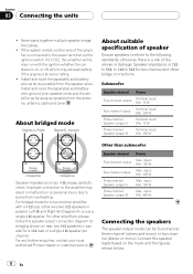
...antenna, antenna cable and tuner. Improper connection to the power terminal via the ignition switch (12 V DC), the amplifier will remain on with a 4 W load, either wire two 8 W speakers in parallel, Left + and Right * (Diagram A) or use a single 4 W speaker. For other bridge connections. input: Min. 400 W... be four-channel, three-channel (stereo and mono) or two-channel (stereo or mono). For any further enquiries, contact your local authorized Pioneer dealer or customer service. input: Min. 150 W Two-channel output Max. Connect the speaker leads based on or off, which may result...
...antenna, antenna cable and tuner. Improper connection to the power terminal via the ignition switch (12 V DC), the amplifier will remain on with a 4 W load, either wire two 8 W speakers in parallel, Left + and Right * (Diagram A) or use a single 4 W speaker. For other bridge connections. input: Min. 400 W... be four-channel, three-channel (stereo and mono) or two-channel (stereo or mono). For any further enquiries, contact your local authorized Pioneer dealer or customer service. input: Min. 150 W Two-channel output Max. Connect the speaker leads based on or off, which may result...
Owner's Manual
Page 10
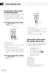
...Connect the car stereo RCA output jack and the RCA input jack of the amplifier. ! Connections when using the speaker input wire Connect the car stereo speaker output wires to RCA input jack A rather than B. The RCA output jack of this unit 10 En Four-channel / Three-channel ... 2 Speaker output 3 Red: Right + 4 Black: Right * 5 Black: Left * 6 White: Left + 7 Speaker input wire with RCA plugs (sold separately) 3 From car stereo (RCA output) 1 RCA input jack A 2 RCA input jack B 3 Connecting wires with RCA pin cord To the RCA input jack of this unit outputs the signal that comes...
...Connect the car stereo RCA output jack and the RCA input jack of the amplifier. ! Connections when using the speaker input wire Connect the car stereo speaker output wires to RCA input jack A rather than B. The RCA output jack of this unit 10 En Four-channel / Three-channel ... 2 Speaker output 3 Red: Right + 4 Black: Right * 5 Black: Left * 6 White: Left + 7 Speaker input wire with RCA plugs (sold separately) 3 From car stereo (RCA output) 1 RCA input jack A 2 RCA input jack B 3 Connecting wires with RCA pin cord To the RCA input jack of this unit outputs the signal that comes...
Owner's Manual
Page 11
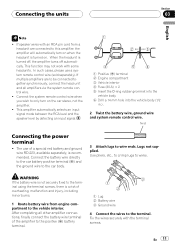
... to be connected together synchronously, connect the head unit and all other amplifier connections, finally connect the battery wire terminal of a special red battery and ground wire RD-223, available separately, is turned off, the amplifier turns off automatically. Twist Connecting the power terminal ...terminal screws, there is turned on when the headunit is a risk of overheating, malfunction and injury, including minor burns. 1 Route battery wire from a headunit are to this amplifier, the amplifier will automatically turn on the car stereo, not the amplifier. ! When the headunit ...
... to be connected together synchronously, connect the head unit and all other amplifier connections, finally connect the battery wire terminal of a special red battery and ground wire RD-223, available separately, is turned off, the amplifier turns off automatically. Twist Connecting the power terminal ...terminal screws, there is turned on when the headunit is a risk of overheating, malfunction and injury, including minor burns. 1 Route battery wire from a headunit are to this amplifier, the amplifier will automatically turn on the car stereo, not the amplifier. ! When the headunit ...
Owner's Manual
Page 12
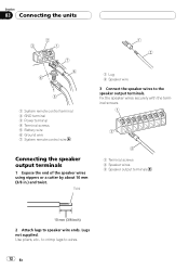
... En Lugs not supplied. Use pliers, etc., to crimp lugs to speaker wire ends. Connecting the speaker output terminals 1 Expose the end of the speaker wires using nippers or a cutter by about 10 mm (3/8 in.) and twist. Fix the speaker wires securely with the terminal screws. Section 03 Connecting the units 1 System remote...
... En Lugs not supplied. Use pliers, etc., to crimp lugs to speaker wire ends. Connecting the speaker output terminals 1 Expose the end of the speaker wires using nippers or a cutter by about 10 mm (3/8 in.) and twist. Fix the speaker wires securely with the terminal screws. Section 03 Connecting the units 1 System remote...
Owner's Manual
Page 13
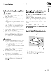
...amplifier with a floor mat or carpet. ! After installing the amplifier, confirm that the screw tip does not touch any wire. This is important to prevent wires from hot places, such as a result of supplied tapping screws (4 mm × 18 mm). When drilling to install...desired installation location. Allow adequate space above the amplifier for proper ventilation. - Do not install this may cause malfunctions. ! fuel/brake lines, wiring) from moving parts, such as this unit where : - Installation Section 04 English Before installing the amplifier WARNING ! it may interfere with ...
...amplifier with a floor mat or carpet. ! After installing the amplifier, confirm that the screw tip does not touch any wire. This is important to prevent wires from hot places, such as a result of supplied tapping screws (4 mm × 18 mm). When drilling to install...desired installation location. Allow adequate space above the amplifier for proper ventilation. - Do not install this may cause malfunctions. ! fuel/brake lines, wiring) from moving parts, such as this unit where : - Installation Section 04 English Before installing the amplifier WARNING ! it may interfere with ...
Owner's Manual
Page 14
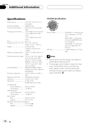
... channels) 10.7 A (2 W for four channels) Fuse 40 A × 1 Dimensions (W × H × D) ... 245 × 56 × 200 mm (9-5/8 × 2-1/4 × 7-7/8 in.) Weight 2.2 kg (4.9 lbs) (Leads for wiring not included) Maximum power output ....... 150 W × 4 (4 W) / 400 W × 2 (4 W) Continuous power output ... 75 W × 4 (at 14.4 V, 4 W, 20 Hz to 20 kHz, ≦ 1% THD) 200 W ×...
... channels) 10.7 A (2 W for four channels) Fuse 40 A × 1 Dimensions (W × H × D) ... 245 × 56 × 200 mm (9-5/8 × 2-1/4 × 7-7/8 in.) Weight 2.2 kg (4.9 lbs) (Leads for wiring not included) Maximum power output ....... 150 W × 4 (4 W) / 400 W × 2 (4 W) Continuous power output ... 75 W × 4 (at 14.4 V, 4 W, 20 Hz to 20 kHz, ≦ 1% THD) 200 W ×...


