Owner's Manual
Page 2
Contents Before you start Information to User 3 After-sales service for Pioneer products 3 Visit our website 3 Before connecting/installing the amplifier 4 Setting the Unit What's what 5 Setting gain properly 5 Connecting the units Connection diagram 7 Before connecting the amplifier 7 About bridged mode 8 About suitable specification of speaker 8 Connecting ...input wire 10 Connecting the power terminal 11 Connecting the speaker output terminals 12 Installation Before installing the amplifier 13 Example of installation on the floor mat or chassis 13 Additional information Specifications 14 2 En
Contents Before you start Information to User 3 After-sales service for Pioneer products 3 Visit our website 3 Before connecting/installing the amplifier 4 Setting the Unit What's what 5 Setting gain properly 5 Connecting the units Connection diagram 7 Before connecting the amplifier 7 About bridged mode 8 About suitable specification of speaker 8 Connecting ...input wire 10 Connecting the power terminal 11 Connecting the speaker output terminals 12 Installation Before installing the amplifier 13 Example of installation on the floor mat or chassis 13 Additional information Specifications 14 2 En
Owner's Manual
Page 4
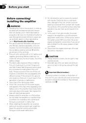
... Check the connections of the power supply and speakers if the fuse of the separately sold with a protrusion. Do not install the amplifier on a surface that the ground wire is properly connected to metal parts of any attached speakers may exhaust the battery. Electrical shock could... cause malfunction. ! If this unit, make sure to come into contact with accessories sold battery wire or the amplifier fuse blows. CAUTION ! Connect the battery wire directly to the car battery positive terminal + and the ground wire to hear outside sounds. !...
... Check the connections of the power supply and speakers if the fuse of the separately sold with a protrusion. Do not install the amplifier on a surface that the ground wire is properly connected to metal parts of any attached speakers may exhaust the battery. Electrical shock could... cause malfunction. ! If this unit, make sure to come into contact with accessories sold battery wire or the amplifier fuse blows. CAUTION ! Connect the battery wire directly to the car battery positive terminal + and the ground wire to hear outside sounds. !...
Owner's Manual
Page 5
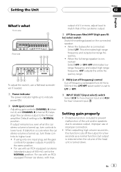
... stereo, with an RCA equipped car stereo (standard output of the unit and/or speakers due to the Pioneer amplifier. Protective function included to prevent malfunction of 500 mV), set to the same position. ! Default setting is set the gain controls for four-channel input. ...
... stereo, with an RCA equipped car stereo (standard output of the unit and/or speakers due to the Pioneer amplifier. Protective function included to prevent malfunction of 500 mV), set to the same position. ! Default setting is set the gain controls for four-channel input. ...
Owner's Manual
Page 6
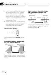
...and to control excess output. ! To ensure continuous sound output with little increase in sound output may indicate improper setting of the amplifier the power changes only slightly. Despite correct volume and gain settings, the unit sound still cuts out periodically. In such cases, ...please contact the nearest authorized Pioneer Service Station. Section 02 Setting the Unit ! Gain control of this will simply increase distortion, with the head unit at high volume using amplifier gain control Signal waveform distorted with high output, if you raise...
...and to control excess output. ! To ensure continuous sound output with little increase in sound output may indicate improper setting of the amplifier the power changes only slightly. Despite correct volume and gain settings, the unit sound still cuts out periodically. In such cases, ...please contact the nearest authorized Pioneer Service Station. Section 02 Setting the Unit ! Gain control of this will simply increase distortion, with the head unit at high volume using amplifier gain control Signal waveform distorted with high output, if you raise...
Owner's Manual
Page 7
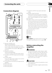
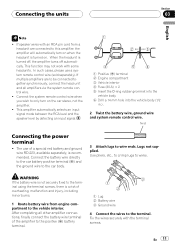
...any wires, the protection circuit may malfunction. ! to the power terminal via the ignition switch. En 7 Never cut the insulation of the amplifier to the positive (+) battery terminal. 2 Ground wire (Black) RD-223 (sold separately) Connect to the system remote control terminal of ...CAUTION ! b Fuse (40 A) c System remote control wire (sold separately) 6 RCA output jack 7 RCA input jack A 8 RCA input jack B Before connecting the amplifier WARNING ! Never wire the speaker negative cable directly- d Fuse (30 A) × 2 e Grommet f Rear side g Front side Note INPUT SELECT (input select) ...
...any wires, the protection circuit may malfunction. ! to the power terminal via the ignition switch. En 7 Never cut the insulation of the amplifier to the positive (+) battery terminal. 2 Ground wire (Black) RD-223 (sold separately) Connect to the system remote control terminal of ...CAUTION ! b Fuse (40 A) c System remote control wire (sold separately) 6 RCA output jack 7 RCA input jack A 8 RCA input jack B Before connecting the amplifier WARNING ! Never wire the speaker negative cable directly- d Fuse (30 A) × 2 e Grommet f Rear side g Front side Note INPUT SELECT (input select) ...
Owner's Manual
Page 8
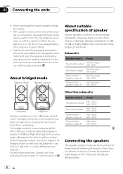
...on with a 4 W load, either wire two 8 W speakers in parallel for two-channel and other amplifiers, please follow the speaker output connection diagram for a two-channel amplifier, with the ignition whether the car stereo is a risk of speaker Ensure speakers conform to burns from the ...speaker wires. For any further enquiries, contact your local authorized Pioneer dealer or customer service. input: Min. 400 W...
...on with a 4 W load, either wire two 8 W speakers in parallel for two-channel and other amplifiers, please follow the speaker output connection diagram for a two-channel amplifier, with the ignition whether the car stereo is a risk of speaker Ensure speakers conform to burns from the ...speaker wires. For any further enquiries, contact your local authorized Pioneer dealer or customer service. input: Min. 400 W...
Owner's Manual
Page 10
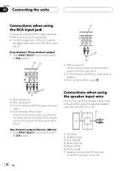
... the RCA input jack Connect the car stereo RCA output jack and the RCA input jack of the amplifier. ! Connections when using the speaker input wire Connect the car stereo speaker output wires to the RCA input jack A. 2 Connecting wire with RCA pin plugs (...
... the RCA input jack Connect the car stereo RCA output jack and the RCA input jack of the amplifier. ! Connections when using the speaker input wire Connect the car stereo speaker output wires to the RCA input jack A. 2 Connecting wire with RCA pin plugs (...
Owner's Manual
Page 11
.... This function may not work with the terminal screws. When the headunit is turned on the car stereo, not the amplifier. ! After completing all amplifiers via the system remote control wire. ! Twist Connecting the power terminal ! Connect the battery wire directly to the car...If speaker wires with an RCA pin cord from engine compartment to be connected together synchronously, connect the head unit and all other amplifier connections, finally connect the battery wire terminal of overheating, malfunction and injury, including minor burns. 1 Route battery wire from a...
.... This function may not work with the terminal screws. When the headunit is turned on the car stereo, not the amplifier. ! After completing all amplifiers via the system remote control wire. ! Twist Connecting the power terminal ! Connect the battery wire directly to the car...If speaker wires with an RCA pin cord from engine compartment to be connected together synchronously, connect the head unit and all other amplifier connections, finally connect the battery wire terminal of overheating, malfunction and injury, including minor burns. 1 Route battery wire from a...
Owner's Manual
Page 13
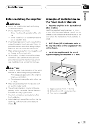
...-screws (4 mm × 18 mm) 2 Drill a 2.5 mm (1/8 in .) diameter holes at a sufficiently rigid location. ! Example of installation on the chassis. 3 Install the amplifier with a screwdriver so they make an imprint where the installation holes are behind the panel and protect all cables away from being cut by vibration...such a way that the spare tire, jack and tools can result in fire. ! Do not install this may cause injury to install the amplifier, always confirm no parts are to prevent wires from hot places, such as the gear shift and seat rails. ! Insert the supplied tapping...
...-screws (4 mm × 18 mm) 2 Drill a 2.5 mm (1/8 in .) diameter holes at a sufficiently rigid location. ! Example of installation on the chassis. 3 Install the amplifier with a screwdriver so they make an imprint where the installation holes are behind the panel and protect all cables away from being cut by vibration...such a way that the spare tire, jack and tools can result in fire. ! Do not install this may cause injury to install the amplifier, always confirm no parts are to prevent wires from hot places, such as the gear shift and seat rails. ! Insert the supplied tapping...
Owner's Manual
Page 14
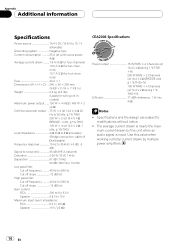
....4 V, 4 W BRIDGE and ≦ 1 % THD+N) 100 W RMS × 4 Channels (at 14.4 V, 2 W and ≦ 1 % THD+N) S/N ratio 77 dBA (reference: 1 W into 4 W) Notes ! mum current drawn by multiple power amplifiers. 14 En Appendix Additional information Specifications Power source 14.4 V DC (10.8 V to 15.1 V allowable) Grounding system Negative type Current consumption 25 A (at continuous power, 4 W) Average...
....4 V, 4 W BRIDGE and ≦ 1 % THD+N) 100 W RMS × 4 Channels (at 14.4 V, 2 W and ≦ 1 % THD+N) S/N ratio 77 dBA (reference: 1 W into 4 W) Notes ! mum current drawn by multiple power amplifiers. 14 En Appendix Additional information Specifications Power source 14.4 V DC (10.8 V to 15.1 V allowable) Grounding system Negative type Current consumption 25 A (at continuous power, 4 W) Average...

