Owner's Manual
Page 2
... Information to User 3 After-sales service for Pioneer products 3 Visit our website 3 Before connecting/installing the amplifier 4 Setting the Unit What's what 5 Setting gain properly 5 Connecting the units Connection diagram 7 Before connecting the amplifier 7 About bridged mode 8 About suitable specification of speaker 8 Connecting the speakers 8 Connections when using the RCA input jack 10 Connections when using the speaker input wire 10 Connecting the power terminal 11 Connecting the speaker output terminals 12 Installation Before installing the amplifier 13 Example of installation on the...
... Information to User 3 After-sales service for Pioneer products 3 Visit our website 3 Before connecting/installing the amplifier 4 Setting the Unit What's what 5 Setting gain properly 5 Connecting the units Connection diagram 7 Before connecting the amplifier 7 About bridged mode 8 About suitable specification of speaker 8 Connecting the speakers 8 Connections when using the RCA input jack 10 Connections when using the speaker input wire 10 Connecting the power terminal 11 Connecting the speaker output terminals 12 Installation Before installing the amplifier 13 Example of installation on the...
Owner's Manual
Page 3
... contact the companies listed below for Pioneer products Please contact the dealer or distributor from where you refer to operate the equipment. After-sales service for repair without appropriate authorization may invalidate the user's right to this information in this unit. We will keep the details of your purchase on the latest products and technologies. 3 Download owner's manuals, order product catalogues...
... contact the companies listed below for Pioneer products Please contact the dealer or distributor from where you refer to operate the equipment. After-sales service for repair without appropriate authorization may invalidate the user's right to this information in this unit. We will keep the details of your purchase on the latest products and technologies. 3 Download owner's manuals, order product catalogues...
Owner's Manual
Page 4
... the ground wire is recommended. Extended use of the car's body. Handling the cord on a flat surface. Connect the battery wire directly to the car battery positive terminal + and the ground wire to metal parts of a special red battery and ground wire RD-223, available separately, is properly connected to the car body. ! Check the connections of the power supply and speakers if the fuse of any attached speakers may exhaust the battery. When installing the amplifier, do...
... the ground wire is recommended. Extended use of the car's body. Handling the cord on a flat surface. Connect the battery wire directly to the car battery positive terminal + and the ground wire to metal parts of a special red battery and ground wire RD-223, available separately, is properly connected to the car body. ! Check the connections of the power supply and speakers if the fuse of any attached speakers may exhaust the battery. When installing the amplifier, do...
Owner's Manual
Page 5
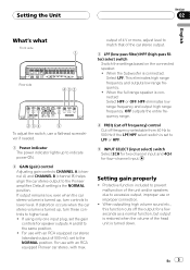
...Pioneer car stereo, with an RCA equipped car stereo (standard output of the head unit is turned down. Default setting is turned up, turn these controls to the same position. ! En 5 Setting gain properly ! When outputting high volume sound etc., this function cuts off frequency selectable from 40 Hz to lower level. Protective function included to the Pioneer amplifier. Setting the Unit Section 02 English What's what Front side Rear side To adjust the switch, use a flathead screwdriver if needed. 1 Power indicator The power indicator lights up to indicate power ON. 2 GAIN (gain...
...Pioneer car stereo, with an RCA equipped car stereo (standard output of the head unit is turned down. Default setting is turned up, turn these controls to the same position. ! En 5 Setting gain properly ! When outputting high volume sound etc., this function cuts off frequency selectable from 40 Hz to lower level. Protective function included to the Pioneer amplifier. Setting the Unit Section 02 English What's what Front side Rear side To adjust the switch, use a flathead screwdriver if needed. 1 Power indicator The power indicator lights up to indicate power ON. 2 GAIN (gain...
Owner's Manual
Page 6
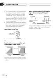
... sound output with little increase in sound output may indicate improper setting of the amplifier the power changes only slightly. Despite correct volume and gain settings, the unit sound still cuts out periodically. Section 02 Setting the Unit ! Gain control of this will simply increase distortion, with the head unit at high volume using amplifier gain control Signal waveform distorted with high output, if you raise the gain of the gain control. In such cases, please contact the nearest authorized Pioneer Service Station. A cut...
... sound output with little increase in sound output may indicate improper setting of the amplifier the power changes only slightly. Despite correct volume and gain settings, the unit sound still cuts out periodically. Section 02 Setting the Unit ! Gain control of this will simply increase distortion, with the head unit at high volume using amplifier gain control Signal waveform distorted with high output, if you raise the gain of the gain control. In such cases, please contact the nearest authorized Pioneer Service Station. A cut...
Owner's Manual
Page 7
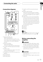
...wires, the protection circuit may malfunction. ! to Connections when using the speaker input wire on page 5. 1 Special red battery wire RD-223 (sold separately) After completing all other equipment. Never wire the speaker negative cable directly- b Fuse (40 A) c System remote control wire (sold separately) a Speaker output terminals Please see Setting the Unit on page 10. Connecting the units Section 03 English Connection diagram 9 Amplifier with cable clamps or adhe- Refer to ground. If the car stereo lacks a system remote control terminal, connect the male terminal...
...wires, the protection circuit may malfunction. ! to Connections when using the speaker input wire on page 5. 1 Special red battery wire RD-223 (sold separately) After completing all other equipment. Never wire the speaker negative cable directly- b Fuse (40 A) c System remote control wire (sold separately) a Speaker output terminals Please see Setting the Unit on page 10. Connecting the units Section 03 English Connection diagram 9 Amplifier with cable clamps or adhe- Refer to ground. If the car stereo lacks a system remote control terminal, connect the male terminal...
Owner's Manual
Page 8
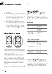
...(Diagram A) or use a single 4 W speaker. About bridged mode About suitable specification of speaker Ensure speakers conform to 8 W for two-channel and other amplifiers, please follow the speaker output connection diagram for a 4 W load or a single 4 W speaker per channel. Other than subwoofer Speaker channel Power Four-channel output Max. input: Min. 400 W Connecting the speakers The speaker output mode can be four-channel, three-channel (stereo and mono) or two-channel (stereo or mono). input: Min. 150 W Three-channel Speaker output B Max. Section 03 Connecting the units...
...(Diagram A) or use a single 4 W speaker. About bridged mode About suitable specification of speaker Ensure speakers conform to 8 W for two-channel and other amplifiers, please follow the speaker output connection diagram for a 4 W load or a single 4 W speaker per channel. Other than subwoofer Speaker channel Power Four-channel output Max. input: Min. 400 W Connecting the speakers The speaker output mode can be four-channel, three-channel (stereo and mono) or two-channel (stereo or mono). input: Min. 150 W Three-channel Speaker output B Max. Section 03 Connecting the units...
Owner's Manual
Page 9
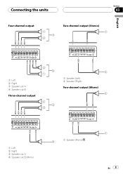
Connecting the units Four-channel output Section 03 Two-channel output (Stereo) English 1 Left 2 Right 3 Speaker out A 4 Speaker out B Three-channel output 1 Speaker (Left) 2 Speaker (Right) Two-channel output (Mono) 1 Left 2 Right 3 Speaker out A 4 Speaker out B (Mono) 1 Speaker (Mono) En 9
Connecting the units Four-channel output Section 03 Two-channel output (Stereo) English 1 Left 2 Right 3 Speaker out A 4 Speaker out B Three-channel output 1 Speaker (Left) 2 Speaker (Right) Two-channel output (Mono) 1 Left 2 Right 3 Speaker out A 4 Speaker out B (Mono) 1 Speaker (Mono) En 9
Owner's Manual
Page 10
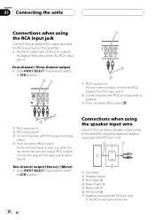
... RCA pin plugs (sold sepa- Two-channel output (Stereo) / (Mono) ! Slide INPUT SELECT (input select) switch to 4CH position. 1 RCA input jack A For two-channel output, connect the RCA plugs to the amplifier using the RCA input jack Connect the car stereo RCA output jack and the RCA input jack of this unit 10 En rately) 4 From car stereo (RCA output) If only one output (RCA output), connect the plug to 2CH position. Section 03 Connecting the units Connections when using the supplied speaker input wire with RCA pin cord. 1 Car Stereo 2 Speaker output 3 Red: Right + 4 Black...
... RCA pin plugs (sold sepa- Two-channel output (Stereo) / (Mono) ! Slide INPUT SELECT (input select) switch to 4CH position. 1 RCA input jack A For two-channel output, connect the RCA plugs to the amplifier using the RCA input jack Connect the car stereo RCA output jack and the RCA input jack of this unit 10 En rately) 4 From car stereo (RCA output) If only one output (RCA output), connect the plug to 2CH position. Section 03 Connecting the units Connections when using the supplied speaker input wire with RCA pin cord. 1 Car Stereo 2 Speaker output 3 Red: Right + 4 Black...
Owner's Manual
Page 11
... function may not work with the terminal screws. If multiple amplifiers are connected to the terminal using the terminal screws, there is recommended. Fix the wires securely with some headunits. WARNING If the battery wire is not securely fixed to this amplifier, the amplifier will automatically turn on . En 11 When the headunit is turned on the car stereo, not the amplifier. ! This amplifier automatically selects an input signal mode between the RCA level and the speaker level by...
... function may not work with the terminal screws. If multiple amplifiers are connected to the terminal using the terminal screws, there is recommended. Fix the wires securely with some headunits. WARNING If the battery wire is not securely fixed to this amplifier, the amplifier will automatically turn on . En 11 When the headunit is turned on the car stereo, not the amplifier. ! This amplifier automatically selects an input signal mode between the RCA level and the speaker level by...
Owner's Manual
Page 12
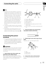
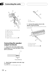
...terminals 1 Expose the end of the speaker wires using nippers or a cutter by about 10 mm (3/8 in.) and twist. Fix the speaker wires securely with the terminal screws. Use pliers, etc., to crimp lugs to speaker wire ends. Twist 1 Terminal screws 2 Speaker wires 3 Speaker output terminals 2 Attach lugs to wires. 12 En Lugs not supplied. Section 03 Connecting the units 1 System remote control terminal 2 GND terminal 3 Power terminal 4 Terminal screws 5 Battery wire 6 Ground wire 7 System remote control wire 1 Lug 2 Speaker wire 3 Connect the speaker wires to the speaker output terminals...
...terminals 1 Expose the end of the speaker wires using nippers or a cutter by about 10 mm (3/8 in.) and twist. Fix the speaker wires securely with the terminal screws. Use pliers, etc., to crimp lugs to speaker wire ends. Twist 1 Terminal screws 2 Speaker wires 3 Speaker output terminals 2 Attach lugs to wires. 12 En Lugs not supplied. Section 03 Connecting the units 1 System remote control terminal 2 GND terminal 3 Power terminal 4 Terminal screws 5 Battery wire 6 Ground wire 7 System remote control wire 1 Lug 2 Speaker wire 3 Connect the speaker wires to the speaker output terminals...
Owner's Manual
Page 13
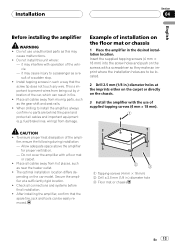
.... ! fuel/brake lines, wiring) from being cut by vibration of a sudden stop. ! fier, ensure the following during installation: - Place all cables away from hot places, such as a result of the car, which can be located. 2 Drill 2.5 mm (1/8 in the desired installation location. The optimal installation location differs de- Place all cables away from moving parts, such as this unit where : - Insert...
.... ! fuel/brake lines, wiring) from being cut by vibration of a sudden stop. ! fier, ensure the following during installation: - Place all cables away from hot places, such as a result of the car, which can be located. 2 Drill 2.5 mm (1/8 in the desired installation location. The optimal installation location differs de- Place all cables away from moving parts, such as this unit where : - Insert...
Owner's Manual
Page 14
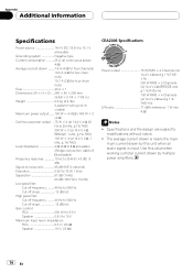
... filter: Cut off frequency 40 Hz to 500 Hz Cut off slope 12 dB/oct Gain control: RCA 200 mV to 6.5 V Speaker 0.8 V to modifications without notice. ! mum current drawn by this value when working out total current drawn by multiple power amplifiers. 14 En Use this unit when an audio signal is nearly the maxi- Specifications and the design are subject to 10 V Maximum input level / impedance: RCA...
... filter: Cut off frequency 40 Hz to 500 Hz Cut off slope 12 dB/oct Gain control: RCA 200 mV to 6.5 V Speaker 0.8 V to modifications without notice. ! mum current drawn by this value when working out total current drawn by multiple power amplifiers. 14 En Use this unit when an audio signal is nearly the maxi- Specifications and the design are subject to 10 V Maximum input level / impedance: RCA...


