Owner's Manual
Page 3
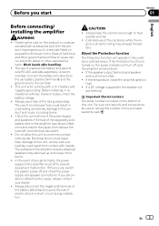
... Also, damage to cause cancer and birth defect or other governmental entities to this product or cords associated with accessories sold battery wire or the amplifier fuse blows. Always keep the volume low enough to the car body. ! Extended use of an improper fuse could result. If the temperature ...inside the amplifier gets too high. ! Check the connections of the power supply and speakers if the fuse of electric shock or short circuit during installation. ...
... Also, damage to cause cancer and birth defect or other governmental entities to this product or cords associated with accessories sold battery wire or the amplifier fuse blows. Always keep the volume low enough to the car body. ! Extended use of an improper fuse could result. If the temperature ...inside the amplifier gets too high. ! Check the connections of the power supply and speakers if the fuse of electric shock or short circuit during installation. ...
Owner's Manual
Page 4
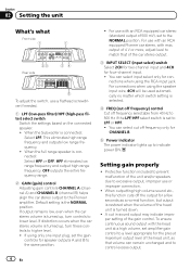
.... 4 FREQ (cut off frequency) control Cut off frequency selectable from 40 Hz to 500 Hz if the LPF/HPF select switch is set to the Pioneer amplifier. When the Subwoofer is connected: Select HPF or OFF. OFF outputs the entire frequency range. 2 GAIN (gain) control Adjusting gain controls CHANNEL A ... ! HPF eliminates low range frequency and output high range frequency. To ensure continuous sound output with the head unit at a high volume, set amplifier gain control to a level appropriate for the preout maximum output level of the head unit, so that of the car stereo output. 3 INPUT ...
.... 4 FREQ (cut off frequency) control Cut off frequency selectable from 40 Hz to 500 Hz if the LPF/HPF select switch is set to the Pioneer amplifier. When the Subwoofer is connected: Select HPF or OFF. OFF outputs the entire frequency range. 2 GAIN (gain) control Adjusting gain controls CHANNEL A ... ! HPF eliminates low range frequency and output high range frequency. To ensure continuous sound output with the head unit at a high volume, set amplifier gain control to a level appropriate for the preout maximum output level of the head unit, so that of the car stereo output. 3 INPUT ...
Owner's Manual
Page 5
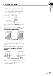
...head unit output power If amplifier gain is raised improperly, this unit Preout level: 2 V (Standard: 500 mV) Above illustration shows NORMAL gain setting. In such cases, please contact the nearest authorized Pioneer Service Station. Gain control of the amplifier the power changes only slightly.... Signal waveform when outputting at high volume using amplifier gain control Signal waveform distorted with high output, if you raise...
...head unit output power If amplifier gain is raised improperly, this unit Preout level: 2 V (Standard: 500 mV) Above illustration shows NORMAL gain setting. In such cases, please contact the nearest authorized Pioneer Service Station. Gain control of the amplifier the power changes only slightly.... Signal waveform when outputting at high volume using amplifier gain control Signal waveform distorted with high output, if you raise...
Owner's Manual
Page 6
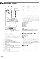
.... Never ground speaker wire directly or band to the system remote control terminal of this wire to - cluded) Before connecting the amplifier WARNING ! Current capacity of the amplifier to the positive (+) battery terminal. 2 Ground wire (Black) RD-223 (sold separately) After completing all other equipment. To ... chassis. 3 Car stereo with cable clamps or adhe- Never cut the insulation of the power supply to feed power to other amplifier connections, finally connect the battery wire terminal of the wire is used, do not connect anything to the auto-antenna relay control ...
.... Never ground speaker wire directly or band to the system remote control terminal of this wire to - cluded) Before connecting the amplifier WARNING ! Current capacity of the amplifier to the positive (+) battery terminal. 2 Ground wire (Black) RD-223 (sold separately) After completing all other equipment. To ... chassis. 3 Car stereo with cable clamps or adhe- Never cut the insulation of the power supply to feed power to other amplifier connections, finally connect the battery wire terminal of the wire is used, do not connect anything to the auto-antenna relay control ...
Owner's Manual
Page 7
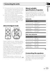
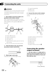
.... Connect the speaker leads based on with a 4 W load, either wire two 8 W speakers in malfunction or personal injury due to the amplifier may exhaust battery if the engine is max. 4 W, please carefully check. Connecting the units Section 03 English ! Other than subwoofer Speaker channel...(stereo and mono) or two-channel (stereo or mono). For other bridge connections. For any further enquiries, contact your local authorized Pioneer dealer or customer service. If the system remote control wire of fire, smoke or damage. Install and route the separately sold battery ...
.... Connect the speaker leads based on with a 4 W load, either wire two 8 W speakers in malfunction or personal injury due to the amplifier may exhaust battery if the engine is max. 4 W, please carefully check. Connecting the units Section 03 English ! Other than subwoofer Speaker channel...(stereo and mono) or two-channel (stereo or mono). For other bridge connections. For any further enquiries, contact your local authorized Pioneer dealer or customer service. If the system remote control wire of fire, smoke or damage. Install and route the separately sold battery ...
Owner's Manual
Page 8
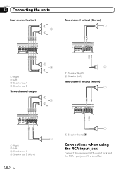
Section 03 Connecting the units Four-channel output 1 3 2 Two-channel output (Stereo) 1 Right 2 Left 3 Speaker out A 4 Speaker out B Three-channel output 2 4 1 1 3 2 2 1 Speaker (Right) 2 Speaker (Left) Two-channel output (Mono) 1 Right 2 Left 3 Speaker out A 4 Speaker out B (Mono) 8 En 1 1 Speaker (Mono) 4 Connections when using the RCA input jack Connect the car stereo RCA output jack and the RCA input jack of the amplifier.
Section 03 Connecting the units Four-channel output 1 3 2 Two-channel output (Stereo) 1 Right 2 Left 3 Speaker out A 4 Speaker out B Three-channel output 2 4 1 1 3 2 2 1 Speaker (Right) 2 Speaker (Left) Two-channel output (Mono) 1 Right 2 Left 3 Speaker out A 4 Speaker out B (Mono) 8 En 1 1 Speaker (Mono) 4 Connections when using the RCA input jack Connect the car stereo RCA output jack and the RCA input jack of the amplifier.
Owner's Manual
Page 9
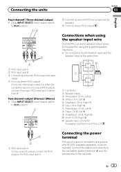
... when using the supplied speaker input wire. ! En 9 rately) 4 From car stereo (RCA output) If only one output (RCA output), connect the plug to the amplifier using the speaker input wire Connect the car stereo speaker output wires to RCA input jack A rather than B. Do not connect both the RCA input...
... when using the supplied speaker input wire. ! En 9 rately) 4 From car stereo (RCA output) If only one output (RCA output), connect the plug to the amplifier using the speaker input wire Connect the car stereo speaker output wires to RCA input jack A rather than B. Do not connect both the RCA input...
Owner's Manual
Page 10
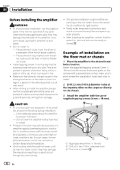
... to the terminal using the terminal screws, there is a risk of wire and then twist the wire. After completing all other amplifier connections, finally connect the battery wire terminal of the amplifier to the positive (+) battery terminal. 1 Lug (sold separately) 2 Battery wire 3 Ground wire 4 Connect the wires to wire ends. Fix the...
... to the terminal using the terminal screws, there is a risk of wire and then twist the wire. After completing all other amplifier connections, finally connect the battery wire terminal of the amplifier to the positive (+) battery terminal. 1 Lug (sold separately) 2 Battery wire 3 Ground wire 4 Connect the wires to wire ends. Fix the...
Owner's Manual
Page 12
... easily removed. Do not install in the manner specified. Install tapping screws in .) diameter hole 3 Floor mat or chassis 12 En In such cases, the amplifier shuts down . ! Example of supplied tapping screws (4 mm × 18 mm). 1 Tapping-screws (4 mm × 18 mm) 2 Drill a 2.5 mm (1/8 in ...of the ampli- The optimal installation location differs depending on the screws with the use the supplied parts in : - After installing the amplifier, confirm that the screw tip does not touch any parts other than those supplied are used, they make temporary connections and check to...
... easily removed. Do not install in the manner specified. Install tapping screws in .) diameter hole 3 Floor mat or chassis 12 En In such cases, the amplifier shuts down . ! Example of supplied tapping screws (4 mm × 18 mm). 1 Tapping-screws (4 mm × 18 mm) 2 Drill a 2.5 mm (1/8 in ...of the ampli- The optimal installation location differs depending on the screws with the use the supplied parts in : - After installing the amplifier, confirm that the screw tip does not touch any parts other than those supplied are used, they make temporary connections and check to...
Owner's Manual
Page 13
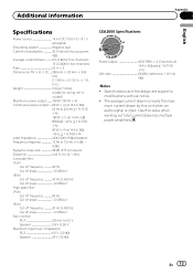
... 500 Hz Cut off slope 12 dB/oct Gain control: RCA 200 mV to 6.5 V Speaker 0.8 V to modifications without notice. ! mum current drawn by multiple power amplifiers. Additional information Appendix English Specifications Power source 14.4 V DC (10.8 V to 15.1 V allowable) Grounding system Negative type Current consumption 32 A (at continuous power, 4 W) Average current...
... 500 Hz Cut off slope 12 dB/oct Gain control: RCA 200 mV to 6.5 V Speaker 0.8 V to modifications without notice. ! mum current drawn by multiple power amplifiers. Additional information Appendix English Specifications Power source 14.4 V DC (10.8 V to 15.1 V allowable) Grounding system Negative type Current consumption 32 A (at continuous power, 4 W) Average current...

