Owner's Manual
Page 2
... deceiving. Over time, your hearing. ESTABLISH A SAFE LEVEL: ! CUSTOMER SUPPORT DIVISION P.O. Set your unit to operate the equipment. Do not turn up the volume so high that you can hear it there. Do not use in Canada http://www.pioneerelectronics.ca 1 Register your purchase on the latest products and technologies. 3 Download owner's manuals, order product catalogues, research new products, and much...
... deceiving. Over time, your hearing. ESTABLISH A SAFE LEVEL: ! CUSTOMER SUPPORT DIVISION P.O. Set your unit to operate the equipment. Do not turn up the volume so high that you can hear it there. Do not use in Canada http://www.pioneerelectronics.ca 1 Register your purchase on the latest products and technologies. 3 Download owner's manuals, order product catalogues, research new products, and much...
Owner's Manual
Page 3
... the amplifier fuse blows. If the Protection function is located on , the power indicator will turn off and check the power supply and speaker connections. If the temperature inside the amplifier gets too high. ! Handling the cord on the enclosed warranty card. Always disconnect the negative * terminal of the battery beforehand to prevent equipment malfunction. Always keep the volume low enough to the speaker out- Extended use a fuse of the car stereo...
... the amplifier fuse blows. If the Protection function is located on , the power indicator will turn off and check the power supply and speaker connections. If the temperature inside the amplifier gets too high. ! Handling the cord on the enclosed warranty card. Always disconnect the negative * terminal of the battery beforehand to prevent equipment malfunction. Always keep the volume low enough to the speaker out- Extended use a fuse of the car stereo...
Owner's Manual
Page 4
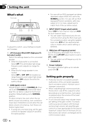
... and output high range frequency. OFF outputs the entire frequency range. 2 GAIN (gain) control Adjusting gain controls CHANNEL A (channel A) and CHANNEL B (channel B) helps align the car stereo output to lower level. You can select cut off frequency only for four-channel input. ! When the full range speaker is connected: Select LPF. If output remains low, even when the car stereo volume is turned up, turn controls to the Pioneer amplifier. For use with an RCA equipped Pioneer car stereo, with an RCA equipped car stereo (standard output of the head unit is set to indicate...
... and output high range frequency. OFF outputs the entire frequency range. 2 GAIN (gain) control Adjusting gain controls CHANNEL A (channel A) and CHANNEL B (channel B) helps align the car stereo output to lower level. You can select cut off frequency only for four-channel input. ! When the full range speaker is connected: Select LPF. If output remains low, even when the car stereo volume is turned up, turn controls to the Pioneer amplifier. For use with an RCA equipped Pioneer car stereo, with an RCA equipped car stereo (standard output of the head unit is set to indicate...
Owner's Manual
Page 5
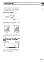
... 5 English In such cases, please contact the nearest authorized Pioneer Service Station. Despite correct volume and gain settings, the unit sound still cuts out periodically. Gain control of the amplifier the power changes only slightly. Relationship between amplifier gain and head unit output power If amplifier gain is raised improperly, this will simply increase distortion, with high output, if you raise the gain of this unit Preout level: 2 V (Standard: 500 mV) Above illustration shows NORMAL...
... 5 English In such cases, please contact the nearest authorized Pioneer Service Station. Despite correct volume and gain settings, the unit sound still cuts out periodically. Gain control of the amplifier the power changes only slightly. Relationship between amplifier gain and head unit output power If amplifier gain is raised improperly, this will simply increase distortion, with high output, if you raise the gain of this unit Preout level: 2 V (Standard: 500 mV) Above illustration shows NORMAL...
Owner's Manual
Page 6
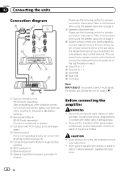
... female terminal can be set. Secure the wiring with RCA pin plugs (sold separately) 6 RCA input jack A 7 RCA input jack B 8 Speaker input terminal (use a connector in adhesive tape. ! Section 03 Connecting the units Connection diagram Please see the following section for speaker connection instructions. b Fuse (25 A) × 2 c Fuse (30 A) × 2 d Grommet e Rear side f Front side Note INPUT SELECT (input select) switch must be connected to metal body or chassis. 3 Car stereo with metal parts in - Never ground speaker wire directly or band to the power terminal...
... female terminal can be set. Secure the wiring with RCA pin plugs (sold separately) 6 RCA input jack A 7 RCA input jack B 8 Speaker input terminal (use a connector in adhesive tape. ! Section 03 Connecting the units Connection diagram Please see the following section for speaker connection instructions. b Fuse (25 A) × 2 c Fuse (30 A) × 2 d Grommet e Rear side f Front side Note INPUT SELECT (input select) switch must be connected to metal body or chassis. 3 Car stereo with metal parts in - Never ground speaker wire directly or band to the power terminal...
Owner's Manual
Page 7
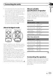
... bridged mode for a 4 W load or a single 4 W speaker per channel. input: Min. 360 W Three-channel Speaker output A Max. If the system remote control wire of fire, smoke or damage. Install and route the separately sold battery wire as far as possible from the speaker wires. input: Min. 120 W Two-channel output Max. For any further enquiries, contact your local authorized Pioneer dealer or customer service. input: Min. 120 W Three-channel Speaker output B Max. En 7 Connecting the units Section 03 English ! Subwoofer Speaker channel Power Four-channel output...
... bridged mode for a 4 W load or a single 4 W speaker per channel. input: Min. 360 W Three-channel Speaker output A Max. If the system remote control wire of fire, smoke or damage. Install and route the separately sold battery wire as far as possible from the speaker wires. input: Min. 120 W Two-channel output Max. For any further enquiries, contact your local authorized Pioneer dealer or customer service. input: Min. 120 W Three-channel Speaker output B Max. En 7 Connecting the units Section 03 English ! Subwoofer Speaker channel Power Four-channel output...
Owner's Manual
Page 8
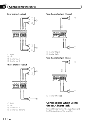
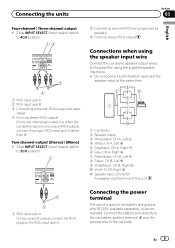
Section 03 Connecting the units Four-channel output 1 3 2 Two-channel output (Stereo) 1 Right 2 Left 3 Speaker out A 4 Speaker out B Three-channel output 2 4 1 1 3 2 2 1 Speaker (Right) 2 Speaker (Left) Two-channel output (Mono) 1 Right 2 Left 3 Speaker out A 4 Speaker out B (Mono) 8 En 1 1 Speaker (Mono) 4 Connections when using the RCA input jack Connect the car stereo RCA output jack and the RCA input jack of the amplifier.
Section 03 Connecting the units Four-channel output 1 3 2 Two-channel output (Stereo) 1 Right 2 Left 3 Speaker out A 4 Speaker out B Three-channel output 2 4 1 1 3 2 2 1 Speaker (Right) 2 Speaker (Left) Two-channel output (Mono) 1 Right 2 Left 3 Speaker out A 4 Speaker out B (Mono) 8 En 1 1 Speaker (Mono) 4 Connections when using the RCA input jack Connect the car stereo RCA output jack and the RCA input jack of the amplifier.
Owner's Manual
Page 9
... Right + 7 Green/black: CH B, Left * 8 Green: CH B, Left + 9 Violet/black: CH B, Right * a Violet: CH B, Right + b Speaker input connector To speaker input terminal of a special red battery and ground wire RD-223, available separately, is used, e.g. when the car stereo has only one input plug is recommended. Connecting the power terminal The use of this unit. 2 3 1 RCA input jack A For two-channel output, connect the RCA plugs to the car body. En 9 Connect the battery wire directly to the car battery positive terminal + and the ground wire to the RCA input jack A.
... Right + 7 Green/black: CH B, Left * 8 Green: CH B, Left + 9 Violet/black: CH B, Right * a Violet: CH B, Right + b Speaker input connector To speaker input terminal of a special red battery and ground wire RD-223, available separately, is used, e.g. when the car stereo has only one input plug is recommended. Connecting the power terminal The use of this unit. 2 3 1 RCA input jack A For two-channel output, connect the RCA plugs to the car body. En 9 Connect the battery wire directly to the car battery positive terminal + and the ground wire to the RCA input jack A.
Owner's Manual
Page 10
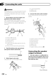
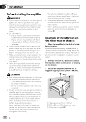
... terminal 2 Ground terminal 3 Power terminal 4 Terminal screws 5 Battery wire 6 Ground wire 7 System remote control wire Connecting the speaker output terminals 1 Use wire cutters or a utility knife to strip the end of the speaker wires to wire ends. Fix the wires securely with the terminal screws. 1 Positive (+) terminal 2 Engine compartment 3 Vehicle interior 4 Fuse (30 A) × 2 5 Insert the O-ring rubber grommet into the vehicle body. 6 Drill a 14 mm hole into the vehicle body. 2 Twist the battery wire, ground wire and system remote control wire. Section 03 Connecting the units...
... terminal 2 Ground terminal 3 Power terminal 4 Terminal screws 5 Battery wire 6 Ground wire 7 System remote control wire Connecting the speaker output terminals 1 Use wire cutters or a utility knife to strip the end of the speaker wires to wire ends. Fix the wires securely with the terminal screws. 1 Positive (+) terminal 2 Engine compartment 3 Vehicle interior 4 Fuse (30 A) × 2 5 Insert the O-ring rubber grommet into the vehicle body. 6 Drill a 14 mm hole into the vehicle body. 2 Twist the battery wire, ground wire and system remote control wire. Section 03 Connecting the units...
Owner's Manual
Page 11
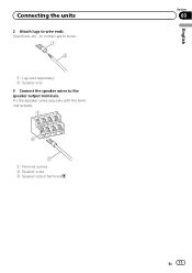
Use pliers, etc., to crimp lugs to wires. 1 Lug (sold separately) 2 Speaker wire 3 Connect the speaker wires to wire ends. Connecting the units 2 Attach lugs to the speaker output terminals. Fix the speaker wires securely with the terminal screws. 1 Terminal screws 2 Speaker wires 3 Speaker output terminals English Section 03 En 11
Use pliers, etc., to crimp lugs to wires. 1 Lug (sold separately) 2 Speaker wire 3 Connect the speaker wires to wire ends. Connecting the units 2 Attach lugs to the speaker output terminals. Fix the speaker wires securely with the terminal screws. 1 Terminal screws 2 Speaker wires 3 Speaker output terminals English Section 03 En 11
Owner's Manual
Page 12
... proper installation, use under high-volume conditions, etc. ver, such as on the chassis. 3 Install the amplifier with a floor mat or carpet. ! When drilling to be located. 2 Drill 2.5 mm (1/8 in the manner specified. fuel/brake lines, wiring) from being cut by vibration of the amplifier, or become loose causing the amplifier to ensure the amplifier and system operate properly. ! Protection function may damage internal parts...
... proper installation, use under high-volume conditions, etc. ver, such as on the chassis. 3 Install the amplifier with a floor mat or carpet. ! When drilling to be located. 2 Drill 2.5 mm (1/8 in the manner specified. fuel/brake lines, wiring) from being cut by vibration of the amplifier, or become loose causing the amplifier to ensure the amplifier and system operate properly. ! Protection function may damage internal parts...
Owner's Manual
Page 13
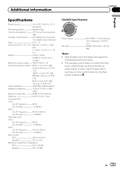
.../oct Gain control: RCA 200 mV to 6.5 V Speaker 0.8 V to modifications without notice. ! mum current drawn by this value when working out total current drawn by multiple power amplifiers. En 13 Use this unit when an audio signal is nearly the maxi- Specifications and the design are subject to 26 V Maximum input level / impedance: RCA 6.5 V / 22 kW Speaker 26 V / 22 kW CEA2006 Specifications Power output 60 W RMS × 4 Channels (at...
.../oct Gain control: RCA 200 mV to 6.5 V Speaker 0.8 V to modifications without notice. ! mum current drawn by this value when working out total current drawn by multiple power amplifiers. En 13 Use this unit when an audio signal is nearly the maxi- Specifications and the design are subject to 26 V Maximum input level / impedance: RCA 6.5 V / 22 kW Speaker 26 V / 22 kW CEA2006 Specifications Power output 60 W RMS × 4 Channels (at...
Owner's Manual
Page 40
... D.F. 11000 TEL: 55-9178-4270 407號8 02) 2657-3588 9樓901-6 0852) 2848-6488 ã 2011 PIONEER CORPORATION. All rights reserved. ã 2011 PIONEER CORPORATION. Printed in China Imprimé en Chine UC P.O. Box 1540, Long Beach, California 90801-1540, U.S.A. LTD. .../Belgique TEL: (0) 3/570.05.11 PIONEER ELECTRONICS ASIACENTRE PTE. Tous droits de reproduction et de traduction réservés. LTD. 5 Arco Lane, Heatherton, Victoria, 3202 Australia TEL: (03) 9586-6300 PIONEER ELECTRONICS OF CANADA, INC. 340 Ferrier Street, Unit 2, Markham, Ontario L3R 2Z5, Canada TEL...
... D.F. 11000 TEL: 55-9178-4270 407號8 02) 2657-3588 9樓901-6 0852) 2848-6488 ã 2011 PIONEER CORPORATION. All rights reserved. ã 2011 PIONEER CORPORATION. Printed in China Imprimé en Chine UC P.O. Box 1540, Long Beach, California 90801-1540, U.S.A. LTD. .../Belgique TEL: (0) 3/570.05.11 PIONEER ELECTRONICS ASIACENTRE PTE. Tous droits de reproduction et de traduction réservés. LTD. 5 Arco Lane, Heatherton, Victoria, 3202 Australia TEL: (03) 9586-6300 PIONEER ELECTRONICS OF CANADA, INC. 340 Ferrier Street, Unit 2, Markham, Ontario L3R 2Z5, Canada TEL...


