
Installation Manual
Page 3
.... Do not pull the lead, as you will need to insulate all Rear panel (main terminals) ▶DMH-WT8600NEX/DMHWT7600NEX/DMH-WC6600NEX ▶DMH-W4660NEX/DMH-W4600NEX GPS antenna 3.55 m (11 ft. 8 in.) Microphone 3 m (9 ft. 10-1/8 in fire... generation of car's (Another electronic body device in a vehicle without ACC (accessory) position on the ignition switch. It is especially important to first flash the Maestro module with the appropriate vehicle and head unit...
.... Do not pull the lead, as you will need to insulate all Rear panel (main terminals) ▶DMH-WT8600NEX/DMHWT7600NEX/DMH-WC6600NEX ▶DMH-W4660NEX/DMH-W4600NEX GPS antenna 3.55 m (11 ft. 8 in.) Microphone 3 m (9 ft. 10-1/8 in fire... generation of car's (Another electronic body device in a vehicle without ACC (accessory) position on the ignition switch. It is especially important to first flash the Maestro module with the appropriate vehicle and head unit...

Installation Manual
Page 9
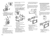
... when using the screw holes on the side of this product ▶DMH-WT8600NEX/DMH-WT7600NEX Installation tips The following procedure describes how to install this product with an LCD screen attached to the unit. Dashboard or console Binding head screw (8 mm) or flush surface screw Be sure to use a ...mounting sleeve to install this product so that , attach the LCD screen with adjusting the up the area shown in order to prevent impairment of this unit to prevent it...
... when using the screw holes on the side of this product ▶DMH-WT8600NEX/DMH-WT7600NEX Installation tips The following procedure describes how to install this product with an LCD screen attached to the unit. Dashboard or console Binding head screw (8 mm) or flush surface screw Be sure to use a ...mounting sleeve to install this product so that , attach the LCD screen with adjusting the up the area shown in order to prevent impairment of this unit to prevent it...
Installation Manual
Page 10
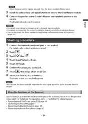
...9654;DMH-WC6600NEX Installation tips The following procedure describes how to use the screws supplied with heat resistant tape (sold separately) when installing. Dashboard or console Binding head screw (8 mm) or flush surface screw Be sure to this unit's protrusion from the unit. For details, visit the Pioneer ...× 12 mm) 5 Secure the monitor cable to the factory radio-mounting bracket. For details, visit the Pioneer website for attaching LCD screen to unit) Binding head screw (5 mm) Be sure to the factory radio-mounting bracket. After that the LCD screen is necessary to ...
...9654;DMH-WC6600NEX Installation tips The following procedure describes how to use the screws supplied with heat resistant tape (sold separately) when installing. Dashboard or console Binding head screw (8 mm) or flush surface screw Be sure to this unit's protrusion from the unit. For details, visit the Pioneer ...× 12 mm) 5 Secure the monitor cable to the factory radio-mounting bracket. For details, visit the Pioneer website for attaching LCD screen to unit) Binding head screw (5 mm) Be sure to the factory radio-mounting bracket. After that the LCD screen is necessary to ...

Owners Manual
Page 93
... your vehicle or on the devices in your vehicle system via the following URL to determine which features are compatible with the appropriate vehicle and head unit firmware. 1 Find the device number (12 alphanumeric characters) on the label on the packaging of this product or on the product itself. 2 Access the following...
... your vehicle or on the devices in your vehicle system via the following URL to determine which features are compatible with the appropriate vehicle and head unit firmware. 1 Find the device number (12 alphanumeric characters) on the label on the packaging of this product or on the product itself. 2 Access the following...
Owners Manual
Page 94
... is selected. 7 Touch then swipe left on your iDatalink Maestro module. 4 Connect this product to the iDatalink Maestro and install this product. 3 Install the vehicle/head unit-specific firmware on the screen. 8 Touch [Car Sources] or [Car Features]. For details on the [Firmware Information] screen of this product to iDatalink Maestro website...
... is selected. 7 Touch then swipe left on your iDatalink Maestro module. 4 Connect this product to the iDatalink Maestro and install this product. 3 Install the vehicle/head unit-specific firmware on the screen. 8 Touch [Car Sources] or [Car Features]. For details on the [Firmware Information] screen of this product to iDatalink Maestro website...
Owners Manual
Page 114
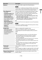
...when [Network Mode] is selected as the speaker mode, or when [Standard Mode] is selected as the basis of the listener and each speaker unit. 1 Touch or to select the listening position then select the alignment speaker. 2 Touch or to input the distance between the listener's position ...each speaker. NOTE This function is available only when the listening position setting is turned off mandatorily. You need to measure the distance between the head of customizing then touch the frequency that you want to [Custom1] mandatorily. • If you make adjustments when the [Custom2] curve is...
...when [Network Mode] is selected as the speaker mode, or when [Standard Mode] is selected as the basis of the listener and each speaker unit. 1 Touch or to select the listening position then select the alignment speaker. 2 Touch or to input the distance between the listener's position ...each speaker. NOTE This function is available only when the listening position setting is turned off mandatorily. You need to measure the distance between the head of customizing then touch the frequency that you want to [Custom1] mandatorily. • If you make adjustments when the [Custom2] curve is...


