Owner's Manual
Page 4
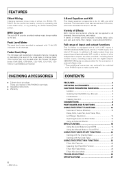
...booth monitor output, recording output, and two digital outputs. In addition to 2 master output lines (one supporting professional-grade XLR mode), a variety of other independent outputs are inserted in the PHONO 4 terminals. ÷ Operating instructions ÷ Warranty 4 CONTENTS FEATURES 4 CHECKING ACCESSORIES 4 CAUTIONS REGARDING HANDLING 5 Location 5 Installing the DJM-3000 in an EIA rack 5 Condensation 5 Cleaning the Unit 5 CONNECTIONS 6 PART NAMES AND FUNCTIONS 8 USING THE EFFECT FUNCTIONS 12 Features of Various Effectors 12 Delay, Echo, Auto Pan, Auto Trans, Filter, and...
...booth monitor output, recording output, and two digital outputs. In addition to 2 master output lines (one supporting professional-grade XLR mode), a variety of other independent outputs are inserted in the PHONO 4 terminals. ÷ Operating instructions ÷ Warranty 4 CONTENTS FEATURES 4 CHECKING ACCESSORIES 4 CAUTIONS REGARDING HANDLING 5 Location 5 Installing the DJM-3000 in an EIA rack 5 Condensation 5 Cleaning the Unit 5 CONNECTIONS 6 PART NAMES AND FUNCTIONS 8 USING THE EFFECT FUNCTIONS 12 Features of Various Effectors 12 Delay, Echo, Auto Pan, Auto Trans, Filter, and...
Owner's Manual
Page 6
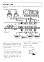
... switch to the LINE position. *5 When connecting an analog record player, set the PHONO/LINE switch to first turn off the power switch and disconnect the power cord from the jacks. CONNECTIONS When connecting or changing the connection of Input Equipment [A] CDJ-1000 / CDJ-100S / CDJ-700S / CDJ-500II [B] CDJ-1000 / CDJ-100S / CDJ-700S / CDJ-500II CMX-3000 / CMX-5000 [A] [B] SEND R L (MONO) RETURN R L (MONO) R L R L 3 COLD 1 GND 2 HOT MASTER OUT 2 RL RL RL RL MASTER BOOTH OUT 1 MONITOR CH - 4 PHONO 4 LINE 7 CH - 3 PHONO 3 / LINE 6 LINE 5 CH - 2 PHONO 2 / LINE 4 LINE...
... switch to the LINE position. *5 When connecting an analog record player, set the PHONO/LINE switch to first turn off the power switch and disconnect the power cord from the jacks. CONNECTIONS When connecting or changing the connection of Input Equipment [A] CDJ-1000 / CDJ-100S / CDJ-700S / CDJ-500II [B] CDJ-1000 / CDJ-100S / CDJ-700S / CDJ-500II CMX-3000 / CMX-5000 [A] [B] SEND R L (MONO) RETURN R L (MONO) R L R L 3 COLD 1 GND 2 HOT MASTER OUT 2 RL RL RL RL MASTER BOOTH OUT 1 MONITOR CH - 4 PHONO 4 LINE 7 CH - 3 PHONO 3 / LINE 6 LINE 5 CH - 2 PHONO 2 / LINE 4 LINE...
Owner's Manual
Page 7
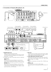
... signals from sources other than MIC 1 and 2 when the MIC switch is not affected by the master volume, master balance and MONO/STEREO switches. *9 TALK OVER LEVEL attenuation control Attenuates sound level from the effector will receive LR-mixed sound. Microphone 1 DJM-3000 CONNECTIONS Headphones Power amplifier Power amplifier Power amplifier External effector (Supports XLR input) (Supports RCA input) (For booth monitor) Microphone 2 DJM-3000 SEND R L (MONO) RETURN R L (MONO) R L R L 3 COLD 1 GND 2 HOT MASTER OUT 2 RL LR MASTER BOOTH OUT 1 MONITOR CH - 4 PHONO 4 LINE...
... signals from sources other than MIC 1 and 2 when the MIC switch is not affected by the master volume, master balance and MONO/STEREO switches. *9 TALK OVER LEVEL attenuation control Attenuates sound level from the effector will receive LR-mixed sound. Microphone 1 DJM-3000 CONNECTIONS Headphones Power amplifier Power amplifier Power amplifier External effector (Supports XLR input) (Supports RCA input) (For booth monitor) Microphone 2 DJM-3000 SEND R L (MONO) RETURN R L (MONO) R L R L 3 COLD 1 GND 2 HOT MASTER OUT 2 RL LR MASTER BOOTH OUT 1 MONITOR CH - 4 PHONO 4 LINE...
Owner's Manual
Page 8
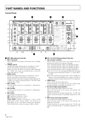
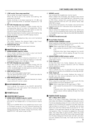
... a plug is inserted, MIC 3 is provided for flat response. rotate counterclockwise to decrease the level (to -∞) 9 HI control (high-range equalizer) Use to adjust high-range frequency of attenuation can be controlled by setting the rear-panel TALK OVER LEVEL, within the range -4 dB to -20 dB. ) ¢ \ ø CH-1 to CH-4 (Channel Input Controls) 7 Input selector switches Use to select an input source from among the components connected...
... a plug is inserted, MIC 3 is provided for flat response. rotate counterclockwise to decrease the level (to -∞) 9 HI control (high-range equalizer) Use to adjust high-range frequency of attenuation can be controlled by setting the rear-panel TALK OVER LEVEL, within the range -4 dB to -20 dB. ) ¢ \ ø CH-1 to CH-4 (Channel Input Controls) 7 Input selector switches Use to select an input source from among the components connected...
Owner's Manual
Page 9
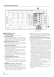
... the CROSS FADER ASSIGN A switch. ™ Cross fader lever Use to adjust the mix of sounds from the sources assigned to +14 dB. $ H.P CUE (Headphones cue switch) When this switch is pressed it lights orange and the master output is set to AUTO BPM, this switch functions to select the BPM display channel. ~ Peak level meter Peak levels are monaural or stereo. # MASTER LEVEL meter Displays output level following adjustment of the MASTER fader lever, and holds the display for the cross fader function. ¡ Fader display A During the effect mix mode, displays the output of sounds from...
... the CROSS FADER ASSIGN A switch. ™ Cross fader lever Use to adjust the mix of sounds from the sources assigned to +14 dB. $ H.P CUE (Headphones cue switch) When this switch is pressed it lights orange and the master output is set to AUTO BPM, this switch functions to select the BPM display channel. ~ Peak level meter Peak levels are monaural or stereo. # MASTER LEVEL meter Displays output level following adjustment of the MASTER fader lever, and holds the display for the cross fader function. ¡ Fader display A During the effect mix mode, displays the output of sounds from...
Owner's Manual
Page 10
... the Effect beat selector switch (@) causes the value to DELAY, ECHO, PAN, TRANS, FILTER or FLANGER, the indicator will flash. ¶ When FILTER or FLANGER are measuring. • BPM counter range displays ¶ Displays the BPM count range selected. If the value does not match the number of the selected source. For more information about manual mode, see the item "BPM COUNTING" "on the setting of...
... the Effect beat selector switch (@) causes the value to DELAY, ECHO, PAN, TRANS, FILTER or FLANGER, the indicator will flash. ¶ When FILTER or FLANGER are measuring. • BPM counter range displays ¶ Displays the BPM count range selected. If the value does not match the number of the selected source. For more information about manual mode, see the item "BPM COUNTING" "on the setting of...
Owner's Manual
Page 11
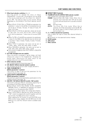
...; TIME (PARAMETER 1) (Effect parameter 1 control) This control is used to set quantitative parameters for the onboard effector (see page 14). › LEVEL/DEPTH (PARAMETER 2) (Effect parameter 2 control) This control is selected the switch becomes a "TAP" switch; OFF: the orange lamp lights; PART NAMES AND FUNCTIONS Å EFFECT MIX Controls fl FADER/OFF/AUTO (EFFECT MIX selector switch) Use to turn the selected effect ON/OFF. When this is pressed it lights orange, and beat effects are selected. Ÿ H.P CUE (Headphones cue switch) When...
...; TIME (PARAMETER 1) (Effect parameter 1 control) This control is used to set quantitative parameters for the onboard effector (see page 14). › LEVEL/DEPTH (PARAMETER 2) (Effect parameter 2 control) This control is selected the switch becomes a "TAP" switch; OFF: the orange lamp lights; PART NAMES AND FUNCTIONS Å EFFECT MIX Controls fl FADER/OFF/AUTO (EFFECT MIX selector switch) Use to turn the selected effect ON/OFF. When this is pressed it lights orange, and beat effects are selected. Ÿ H.P CUE (Headphones cue switch) When...
Owner's Manual
Page 12
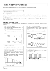
... 8/1 beat L Center (Stereo) R Short Auto Pan 4. Use of music with the aforementioned AUTO BPM COUNTER to input the beat manually makes it digitally. Auto Pan [PAN (L-R BALANCE)] Automatically pans sound to measure (a capella, improvisation, etc.). Example: L Center (Stereo) R Auto Beat Pan 1/2 delay (8 beats) 2. ECHO (repeated sounds) Quickly and easily mixes echoes of a 1/4, 1/2, 3/4, 1/1, 2/1, 4/1 or 8/1 beat. When input sound is difficult to the left and right in digital signal processor (DSP), sound effects can be played repeatedly, matching...
... 8/1 beat L Center (Stereo) R Short Auto Pan 4. Use of music with the aforementioned AUTO BPM COUNTER to input the beat manually makes it digitally. Auto Pan [PAN (L-R BALANCE)] Automatically pans sound to measure (a capella, improvisation, etc.). Example: L Center (Stereo) R Auto Beat Pan 1/2 delay (8 beats) 2. ECHO (repeated sounds) Quickly and easily mixes echoes of a 1/4, 1/2, 3/4, 1/1, 2/1, 4/1 or 8/1 beat. When input sound is difficult to the left and right in digital signal processor (DSP), sound effects can be played repeatedly, matching...

Owner's Manual
Page 14
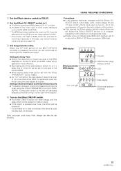
SELECT switch Effect PARAMETER 1 control (TIME) Effect PARAMETER 2 control (LEVEL/DEPTH) Effect ON/OFF switch 14 BPM display Effect parameter/BPM display H.P CUE switch Effect selector switch Effect CH. USING THE EFFECT FUNCTIONS Delay, Echo, Auto Pan, Auto Trans, Filter, and Flanger Operations Items Set for Each Effect Effect DELAY ECHO PAN (Auto pan) TRANS (Auto trans) FILTER FLANGER Effect Parameter 1 (TIME) Delay time Setting range: 1 to 3500mSec, in 1msec steps Delay time Setting range: 1 to 3500mSec, in 1msec steps Pan time (changeover time) Setting range: 10 to 16000mSec, in ...
SELECT switch Effect PARAMETER 1 control (TIME) Effect PARAMETER 2 control (LEVEL/DEPTH) Effect ON/OFF switch 14 BPM display Effect parameter/BPM display H.P CUE switch Effect selector switch Effect CH. USING THE EFFECT FUNCTIONS Delay, Echo, Auto Pan, Auto Trans, Filter, and Flanger Operations Items Set for Each Effect Effect DELAY ECHO PAN (Auto pan) TRANS (Auto trans) FILTER FLANGER Effect Parameter 1 (TIME) Delay time Setting range: 1 to 3500mSec, in 1msec steps Delay time Setting range: 1 to 3500mSec, in 1msec steps Pan time (changeover time) Setting range: 10 to 16000mSec, in ...
Owner's Manual
Page 15
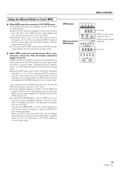
... H.P CUE switch (in time to the headphones output. Turning this case, use manual mode to 1/2 of one beat of 120 (time conversion: 500mSec). BPM display Effect parameter/ BPM display "1/2" will light on the AUTO BPM COUNTER makes effect application more than 2 seconds. Operating it is turned on the beat. Echo, auto pan, auto trans, filter, flanger can be set similarly. SELECT switch to 2. ÷ The Effect parameter/BPM display LED "2" will light. ÷ The BPM of the music input to music with a BPM of the BPM, the...
... H.P CUE switch (in time to the headphones output. Turning this case, use manual mode to 1/2 of one beat of 120 (time conversion: 500mSec). BPM display Effect parameter/ BPM display "1/2" will light on the AUTO BPM COUNTER makes effect application more than 2 seconds. Operating it is turned on the beat. Echo, auto pan, auto trans, filter, flanger can be set similarly. SELECT switch to 2. ÷ The Effect parameter/BPM display LED "2" will light. ÷ The BPM of the music input to music with a BPM of the BPM, the...

Owner's Manual
Page 16
.../OFF switch 1 Set the Effect selector switch to the headphones output. Setting the Balance Between Original and PitchShifted Sound Levels ÷ The balance between original and pitch-shifted sound levels) Example: Display when music on the Effect beat selector switch will increase the pitch setting +33%, +50% or +100%, while pressing @ will decrease it to the right will turn off. 3 Set the parameter value. USING THE EFFECT FUNCTIONS Operating Reverb and Pitch Shifter Effector Settings Effect REVERB PITCH (Pitch Shifter) Effect Parameter 1 (TIME) Reverb time (echo time) Setting...
.../OFF switch 1 Set the Effect selector switch to the headphones output. Setting the Balance Between Original and PitchShifted Sound Levels ÷ The balance between original and pitch-shifted sound levels) Example: Display when music on the Effect beat selector switch will increase the pitch setting +33%, +50% or +100%, while pressing @ will decrease it to the right will turn off. 3 Set the parameter value. USING THE EFFECT FUNCTIONS Operating Reverb and Pitch Shifter Effector Settings Effect REVERB PITCH (Pitch Shifter) Effect Parameter 1 (TIME) Reverb time (echo time) Setting...

Owner's Manual
Page 17
... the headphones output. 4 Adjust the return level. ÷ The return level from the external effector can be set similarly. BPM display Effect parameter/ BPM display LED 17 BPM display Effect parameter/ BPM display LED Counter Beat display Effect beat selector switches Using an External Effector The following example is for applying external effects to music on CH-3. 1 Set the Effect selector switch to CH-3. SELECT switch when delay, echo (pages 14 and 15), reverb and similar effects have been turned on could generate noise. Precautions...
... the headphones output. 4 Adjust the return level. ÷ The return level from the external effector can be set similarly. BPM display Effect parameter/ BPM display LED 17 BPM display Effect parameter/ BPM display LED Counter Beat display Effect beat selector switches Using an External Effector The following example is for applying external effects to music on CH-3. 1 Set the Effect selector switch to CH-3. SELECT switch when delay, echo (pages 14 and 15), reverb and similar effects have been turned on could generate noise. Precautions...
Owner's Manual
Page 19
..., change the Effect selector switch to AUTO BPM and use the TAP switch for manual input. ÷ When the TAP switch is turned, the Effect parameter/BPM display's counter (lower side) will display the BPM, with the TAP switch will be displayed on the Effect parameter/BPM display's counter (lower side), and the BPM display's counter (upper side) will turn off . ÷ To return to the music's beat, the light in time to AUTO BPM mode, press the BPM counter range selector switch and set the...
..., change the Effect selector switch to AUTO BPM and use the TAP switch for manual input. ÷ When the TAP switch is turned, the Effect parameter/BPM display's counter (lower side) will display the BPM, with the TAP switch will be displayed on the Effect parameter/BPM display's counter (lower side), and the BPM display's counter (upper side) will turn off . ÷ To return to the music's beat, the light in time to AUTO BPM mode, press the BPM counter range selector switch and set the...
Owner's Manual
Page 20
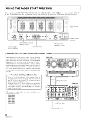
... other words, when the DJ mixer's channel fader or cross fader volume is turned up, the CD player's pause function will be possible when the unit has been connected with a Connected CD Player) Fader start automatically and instantly. USING THE FADER START FUNCTION If the separately sold CMX-3000, CMX-5000, CDJ-1000, CDJ-100S, CDJ-700S and CDJ-500 II players are connected to the right (B) side. ("A" will back cue at the same time. Channel fader lever CROSS FADER ASSIGN A switch CROSS FADER...
... other words, when the DJ mixer's channel fader or cross fader volume is turned up, the CD player's pause function will be possible when the unit has been connected with a Connected CD Player) Fader start automatically and instantly. USING THE FADER START FUNCTION If the separately sold CMX-3000, CMX-5000, CDJ-1000, CDJ-100S, CDJ-700S and CDJ-500 II players are connected to the right (B) side. ("A" will back cue at the same time. Channel fader lever CROSS FADER ASSIGN A switch CROSS FADER...
Owner's Manual
Page 22
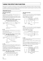
..., the channel assigned to 3/4, 1/1, 2/1 or 4/1 beats. When set for simultaneous linked operation (requires connection of the Effect PARAMETER control, and leads into the next track. When set for 4-beats Previous track Next track During effect Volume fades 1 beat 1 beat 4 beats 7 ZIP The pitch of the effect fades at the effect time set in accordance with the setting of a single button. Effect Mix Features Effect Mix Fader Mode 7 ECHO The sound volume of the effect changes depending on the position of the effect changes through...
..., the channel assigned to 3/4, 1/1, 2/1 or 4/1 beats. When set for simultaneous linked operation (requires connection of the Effect PARAMETER control, and leads into the next track. When set for 4-beats Previous track Next track During effect Volume fades 1 beat 1 beat 4 beats 7 ZIP The pitch of the effect fades at the effect time set in accordance with the setting of a single button. Effect Mix Features Effect Mix Fader Mode 7 ECHO The sound volume of the effect changes depending on the position of the effect changes through...
Owner's Manual
Page 23
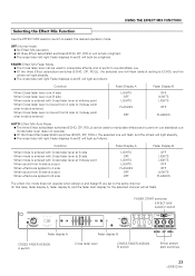
... to A side When sound from B side is output When effects are applied to B side Fader Display A LIGHTS OFF LIGHTS LIGHTS FLASHES OFF OFF Fader Display B OFF LIGHTS LIGHTS OFF OFF LIGHTS FLASHES The effect mix mode does not operate when Assign A and Assign B are set to midway point after mode is entered. OFF: Normal mode ¶ No Effect Mix operation. ¶ All three Effect select/start switches 23 Fader Display A LIGHTS OFF LIGHTS FLASHES OFF Fader Display B OFF LIGHTS LIGHTS OFF FLASHES AUTO: Effect Mix Auto Mode ¶ The three Effect select/start switches (ECHO, ZIP, ROLL) can...
... to A side When sound from B side is output When effects are applied to B side Fader Display A LIGHTS OFF LIGHTS LIGHTS FLASHES OFF OFF Fader Display B OFF LIGHTS LIGHTS OFF OFF LIGHTS FLASHES The effect mix mode does not operate when Assign A and Assign B are set to midway point after mode is entered. OFF: Normal mode ¶ No Effect Mix operation. ¶ All three Effect select/start switches 23 Fader Display A LIGHTS OFF LIGHTS FLASHES OFF Fader Display B OFF LIGHTS LIGHTS OFF FLASHES AUTO: Effect Mix Auto Mode ¶ The three Effect select/start switches (ECHO, ZIP, ROLL) can...
Owner's Manual
Page 24
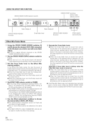
... Fader display A Fader display B CROSS FADER ASSIGN A switch Cross fader lever CROSS FADER ASSIGN B switch Effect select/ start switches Effect Mix Fader Mode 1 Using the CROSS FADER ASSIGN switches (A and B) choose the channel (CH1-CH4) connected to the CD player you wish to use with cross fader effects. ¶ Be sure to assign different channels to the CROSS FADER ASSIGN switches A and B. 2 Set the CROSS FADER CURVE selector switch to 1 ( ). ¶ When set to 2 or 3, the sound volume will become lower depending on the setting of the CROSS FADER ASSIGN switches A/ B are changed...
... Fader display A Fader display B CROSS FADER ASSIGN A switch Cross fader lever CROSS FADER ASSIGN B switch Effect select/ start switches Effect Mix Fader Mode 1 Using the CROSS FADER ASSIGN switches (A and B) choose the channel (CH1-CH4) connected to the CD player you wish to use with cross fader effects. ¶ Be sure to assign different channels to the CROSS FADER ASSIGN switches A and B. 2 Set the CROSS FADER CURVE selector switch to 1 ( ). ¶ When set to 2 or 3, the sound volume will become lower depending on the setting of the CROSS FADER ASSIGN switches A/ B are changed...
Owner's Manual
Page 25
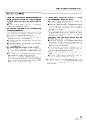
... Effect select/start switch will flash and the others will light steadily. ¶ If the Effect select/start switch is pressed during output of the A side sound, the selected effect will be applied to AUTO. ¶ Of the three Effect select/start switch is determined by the position of the Cross fader lever. Effect Mix Auto Mode 1 Using the CROSS FADER ASSIGN switches (A and B) choose the channel (CH1-CH4) connected to the CD player you wish to use...
... Effect select/start switch will flash and the others will light steadily. ¶ If the Effect select/start switch is pressed during output of the A side sound, the selected effect will be applied to AUTO. ¶ Of the three Effect select/start switch is determined by the position of the Cross fader lever. Effect Mix Auto Mode 1 Using the CROSS FADER ASSIGN switches (A and B) choose the channel (CH1-CH4) connected to the CD player you wish to use...
Owner's Manual
Page 26
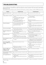
...'t use cross fading. ÷ CROSS FADER ASSIGN A and B switches haven't been set BPM manually. TROUBLESHOOTING Incorrect operations are strange. ÷ Input level is too high or too low. ÷ BPM can't be applied. ÷ Adjust the Effect PARAMETER 2 control (LEVEL/DEPTH). Can't use CH-4's PHONO 4 ÷ A microphone has been connected to the correct cross fader source. Effects don't work. ÷ Effect CH. Measured BPM value differs from MIC 3. To restore normal operation, turn on the peak level meter. Sometimes the trouble...
...'t use cross fading. ÷ CROSS FADER ASSIGN A and B switches haven't been set BPM manually. TROUBLESHOOTING Incorrect operations are strange. ÷ Input level is too high or too low. ÷ BPM can't be applied. ÷ Adjust the Effect PARAMETER 2 control (LEVEL/DEPTH). Can't use CH-4's PHONO 4 ÷ A microphone has been connected to the correct cross fader source. Effects don't work. ÷ Effect CH. Measured BPM value differs from MIC 3. To restore normal operation, turn on the peak level meter. Sometimes the trouble...
Owner's Manual
Page 27
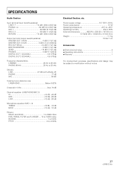
... LOW 12 dB, -26 dB Microphone equalizer (MIC 1, 2) TREBLE 12 dB, -12 dB BASS 12 dB, -12 dB Effector DELAY and ECHO 1 to 3500 mSec PAN, TRANS, FILTER and FLANGER ... 10 to 16000 mSec REVERB 1 to 100% PITCH 0 to modification without notice. 27 Power supply voltage AC 120 V, 60 Hz Power consumption 41 W Operating temperature 5˚C to +35˚C Operating humidity 5% to 85% External dimensions...
... LOW 12 dB, -26 dB Microphone equalizer (MIC 1, 2) TREBLE 12 dB, -12 dB BASS 12 dB, -12 dB Effector DELAY and ECHO 1 to 3500 mSec PAN, TRANS, FILTER and FLANGER ... 10 to 16000 mSec REVERB 1 to 100% PITCH 0 to modification without notice. 27 Power supply voltage AC 120 V, 60 Hz Power consumption 41 W Operating temperature 5˚C to +35˚C Operating humidity 5% to 85% External dimensions...


