Owner's Manual
Page 7
... auto antenna setting 160 - Switching the muting/attenuation timing 161 - Displaying the "AV Sound Settings" menu 163 - Using subwoofer output 166 - Flow of the navigation guidance 162 - Basic commands 170 - Selecting a channel from the list 148 - Selecting a SIRIUS channel directly 152 - Setting video input 1 (AV1) 160...148 - Displaying Game Information 155 Using AV input Using AV1 156 Using AV2 156 Using the touch panel keys 156 Using the external unit (EXT1, EXT2) Reading the screen 157 Using the touch panel keys 157 Other functions Selecting the video for "Rear display" 158 ...
... auto antenna setting 160 - Switching the muting/attenuation timing 161 - Displaying the "AV Sound Settings" menu 163 - Using subwoofer output 166 - Flow of the navigation guidance 162 - Basic commands 170 - Selecting a channel from the list 148 - Selecting a SIRIUS channel directly 152 - Setting video input 1 (AV1) 160...148 - Displaying Game Information 155 Using AV input Using AV1 156 Using AV2 156 Using the touch panel keys 156 Using the external unit (EXT1, EXT2) Reading the screen 157 Using the touch panel keys 157 Other functions Selecting the video for "Rear display" 158 ...
Owner's Manual
Page 25
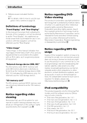
...to as protected by Macrovision Corporation, and is attached to the body of terminology "Front Display" and "Rear Display" In this navigation unit will be referred to as the "Front Display". Definitions of this manual, the screen that is intended for home and other rights... Chapter 01 Introduction ! Ver. 1.3 ! "SD memory card" The SD memory card and SDHC memory card are indicated like this navigation unit will be referred to use of certain U.S. iPod classic; patents and other intellectual property rights owned by Macrovision Corporation and other limited viewing...
...to as protected by Macrovision Corporation, and is attached to the body of terminology "Front Display" and "Rear Display" In this navigation unit will be referred to as the "Front Display". Definitions of this manual, the screen that is intended for home and other rights... Chapter 01 Introduction ! Ver. 1.3 ! "SD memory card" The SD memory card and SDHC memory card are indicated like this navigation unit will be referred to use of certain U.S. iPod classic; patents and other intellectual property rights owned by Macrovision Corporation and other limited viewing...

Owner's Manual
Page 29
...disc is not fully inserted. To prevent data loss and damage to recover the data. Doing so may damage the card. p This unit may break this navigation system until the LCD panel completely opens or closes. En 29 Basic operation Chapter 02 Basic operation ! Doing so may not achieve ... is open. Press the middle of the SD memory card gently and pull out straight. The LCD panel closes. Pioneer accepts no liability for damages, costs or expenses arising from this navigation system when the LCD panel is not guaranteed. Doing so may damage the card. ! Inserting a disc 1 Press...
...disc is not fully inserted. To prevent data loss and damage to recover the data. Doing so may damage the card. p This unit may break this navigation system until the LCD panel completely opens or closes. En 29 Basic operation Chapter 02 Basic operation ! Doing so may not achieve ... is open. Press the middle of the SD memory card gently and pull out straight. The LCD panel closes. Pioneer accepts no liability for damages, costs or expenses arising from this navigation system when the LCD panel is not guaranteed. Doing so may damage the card. ! Inserting a disc 1 Press...

Owner's Manual
Page 94
...fuel cost You can estimate the fuel cost to your destination by using the utility program "AVIC FEEDS" which is set to [Gallon]. Entering the fueling information When you enter the fueling information to the navigation system, and export the data to a gallon. - If the entries reach the maximum ...! [Freeway Gas Mileage]: Enter the fuel cost when you drive on the freeway. The "Gas Mileage Setting" screen appears. ! [Gas Unit]: Set the fuel unit. ! [Currency]: Set the unit of "Gas Price Calculation" en- p Up to [Gallon]. You can be stored. p How the fuel cost is set to 24 sets...
...fuel cost You can estimate the fuel cost to your destination by using the utility program "AVIC FEEDS" which is set to [Gallon]. Entering the fueling information When you enter the fueling information to the navigation system, and export the data to a gallon. - If the entries reach the maximum ...! [Freeway Gas Mileage]: Enter the fuel cost when you drive on the freeway. The "Gas Mileage Setting" screen appears. ! [Gas Unit]: Set the fuel unit. ! [Currency]: Set the unit of "Gas Price Calculation" en- p Up to [Gallon]. You can be stored. p How the fuel cost is set to 24 sets...
Owner's Manual
Page 158
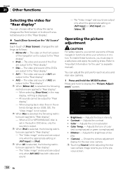
...cannot be output for the user" (a separate manual). p When iPod is displayed. - To enable these navigation functions while your vehicle is emphasized) ! Refer to show the same image as follows: ! Color - Shows... "Rear display" ! The video on the "AV Source" menu. The video and sound of the navigation unit is output to "Rear display". - AV2 - The video and sound of dis- When playing back video... files on the external storage device (USB, SD), the "Video image" is output. When a CD or MP3/WMA/AAC disc is set in the built-in motion. p When AV is selected, the following...
...cannot be output for the user" (a separate manual). p When iPod is displayed. - To enable these navigation functions while your vehicle is emphasized) ! Refer to show the same image as follows: ! Color - Shows... "Rear display" ! The video on the "AV Source" menu. The video and sound of the navigation unit is output to "Rear display". - AV2 - The video and sound of dis- When playing back video... files on the external storage device (USB, SD), the "Video image" is output. When a CD or MP3/WMA/AAC disc is set in the built-in motion. p When AV is selected, the following...
Owner's Manual
Page 161
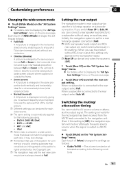
ideal for the mute signal has been received from the MUTE lead connected to the navigation unit. (Even if this setting is [Off], the navigation system will mute or attenuate the audio source volume when the signal is output via MUTE lead.) % Touch [Mute] on the author's .... ! Each touch of [Mute] changes the settings as follows: ! p Different settings can be stored for a rear full-range speaker connection (Full). p The navigation map and the rear view camera picture is enlarged in the same proportion both vertically and horizontally; p Both rear speaker leads output and RCA rear...
ideal for the mute signal has been received from the MUTE lead connected to the navigation unit. (Even if this setting is [Off], the navigation system will mute or attenuate the audio source volume when the signal is output via MUTE lead.) % Touch [Mute] on the author's .... ! Each touch of [Mute] changes the settings as follows: ! p Different settings can be stored for a rear full-range speaker connection (Full). p The navigation map and the rear view camera picture is enlarged in the same proportion both vertically and horizontally; p Both rear speaker leads output and RCA rear...

Owner's Manual
Page 162
...language other than "English" on "Voice language", this setting is ended. Switching the muting/ attenuation level You can set the speaker to the navigation unit, navigation voice guidance cannot be attenuated or muted. Each touch of [Guidance/Tel SP] changes the settings as follows: ! 20dB - The volume ..., iPod operations (such as [Shuffle], [Menu], or [Video]) are possible during the sound is activated. ! Off - When the navigation outputs the guidance voice. - Tel/VR - Right SP - Change the setting according to the navigation unit. Chapter 32 Customizing preferences -
...language other than "English" on "Voice language", this setting is ended. Switching the muting/ attenuation level You can set the speaker to the navigation unit, navigation voice guidance cannot be attenuated or muted. Each touch of [Guidance/Tel SP] changes the settings as follows: ! 20dB - The volume ..., iPod operations (such as [Shuffle], [Menu], or [Video]) are possible during the sound is activated. ! Off - When the navigation outputs the guidance voice. - Tel/VR - Right SP - Change the setting according to the navigation unit. Chapter 32 Customizing preferences -

Owner's Manual
Page 201
...difficult to direct sunlight as much as possible. ! The product lifetime of the LED backlight is used inside the navigation unit, resulting in possible damage. ! In that air from the cooler may scratch it to see if it . Do...become very hot, resulting in high temperatures. ! The LCD screen can scratch easily. light may appear on it as this navigation system, avoid exposing it . ! Never touch the LCD screen with a soft dry cloth. ! When the LCD screen ...system power off, then wipe with anything besides your dealer or the nearest authorized PIONEER Service Station.
...difficult to direct sunlight as much as possible. ! The product lifetime of the LED backlight is used inside the navigation unit, resulting in possible damage. ! In that air from the cooler may scratch it to see if it . Do...become very hot, resulting in high temperatures. ! The LCD screen can scratch easily. light may appear on it as this navigation system, avoid exposing it . ! Never touch the LCD screen with a soft dry cloth. ! When the LCD screen ...system power off, then wipe with anything besides your dealer or the nearest authorized PIONEER Service Station.
Installation Manual
Page 2
..." (AV2) 18 When connecting the external unit featuring video source 19 Installation Precautions before connecting the system 5 Before installing this navigation system 21 2 En - Installation notes 23 - Mounting on the side of the navigation unit 22 Installing the GPS antenna 23 - Installation...antenna inside the vehicle (on the steering column 26 - Parts supplied 22 - Contents IMPORTANT INFORMATION ABOUT YOUR NEW NAVIGATION SYSTEM AND THIS MANUAL 3 IMPORTANT SAFEGUARDS PLEASE READ ALL OF THESE INSTRUCTIONS REGARDING YOUR NAVIGATION SYSTEM AND RETAIN THEM FOR FUTURE REFERENCE...
..." (AV2) 18 When connecting the external unit featuring video source 19 Installation Precautions before connecting the system 5 Before installing this navigation system 21 2 En - Installation notes 23 - Mounting on the side of the navigation unit 22 Installing the GPS antenna 23 - Installation...antenna inside the vehicle (on the steering column 26 - Parts supplied 22 - Contents IMPORTANT INFORMATION ABOUT YOUR NEW NAVIGATION SYSTEM AND THIS MANUAL 3 IMPORTANT SAFEGUARDS PLEASE READ ALL OF THESE INSTRUCTIONS REGARDING YOUR NAVIGATION SYSTEM AND RETAIN THEM FOR FUTURE REFERENCE...
Installation Manual
Page 7
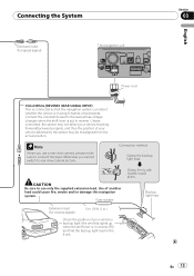
... this lead as the power supply lead for the external power amps. Be sure not to use this lead to an external power amp's system remote control terminal (max. 300 mA 12 V DC). When the ignition switch is turned on (ACC ON), a control signal is output through the blue... or antenna booster. Be sure not to use this lead to the auto-antenna relay control terminal or the antenna booster power control terminal. ! The navigation unit Power cord Connector Extension lead (for reverse signal) Extension lead (for the blue/white lead ! The control signal is switched off. ! Connect to ...
... this lead as the power supply lead for the external power amps. Be sure not to use this lead to an external power amp's system remote control terminal (max. 300 mA 12 V DC). When the ignition switch is turned on (ACC ON), a control signal is output through the blue... or antenna booster. Be sure not to use this lead to the auto-antenna relay control terminal or the antenna booster power control terminal. ! The navigation unit Power cord Connector Extension lead (for reverse signal) Extension lead (for the blue/white lead ! The control signal is switched off. ! Connect to ...
Installation Manual
Page 8
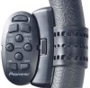
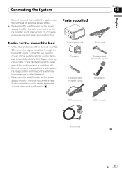
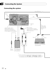
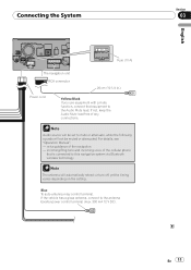
... (e.g. ND-MDT10) (sold separately) *1 - Antenna jack USB connector Connect either the interface cable for the Wired Remote Control Adapters (sold separately). Section 03 Connecting the System Connecting the system Green The navigation unit 5 m (16 ft. 5 in.) Blue WIRED REMOTE INPUT Please see the Instruction Manual for iPod or an appropriate USB storage device. 2 m (6 ft...
... (e.g. ND-MDT10) (sold separately) *1 - Antenna jack USB connector Connect either the interface cable for the Wired Remote Control Adapters (sold separately). Section 03 Connecting the System Connecting the system Green The navigation unit 5 m (16 ft. 5 in.) Blue WIRED REMOTE INPUT Please see the Instruction Manual for iPod or an appropriate USB storage device. 2 m (6 ft...
Installation Manual
Page 11
... on the setting. voice guidance of any connections. incoming Ring tone and incoming voice of the cellular phone that equipment to this navigation system via Bluetooth wireless technology Note The antenna will not be set to the antenna booster power control terminal (max. 300 mA 12...Section 03 En 11 Blue To auto-antenna relay control terminal. For details, see "Operation Manual". - Connecting the System Fuse (10 A) The navigation unit RCA connector 26 cm (10-1/4 in.) Power cord Yellow/Black If you use equipment with a mute function, connect that is connected to the ...
... on the setting. voice guidance of any connections. incoming Ring tone and incoming voice of the cellular phone that equipment to this navigation system via Bluetooth wireless technology Note The antenna will not be set to the antenna booster power control terminal (max. 300 mA 12...Section 03 En 11 Blue To auto-antenna relay control terminal. For details, see "Operation Manual". - Connecting the System Fuse (10 A) The navigation unit RCA connector 26 cm (10-1/4 in.) Power cord Yellow/Black If you use equipment with a mute function, connect that is connected to the ...
Installation Manual
Page 13
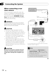
... in reverse. CAUTION Be sure to use a rear view camera, please make sure to connect this navigation system. Use of your vehicle's backup light (the one that the navigation system can detect whether the vehicle is moving forwards or backwards. Otherwise you use only the supplied extension... to rear view camera picture. Fuse resistor Clamp firmly with needle-nosed pliers. Backup light lead Extension lead (for speed signal) The navigation unit English Section 03 Power cord Violet/White (REVERSE GEAR SIGNAL INPUT) This is connected so that lights up when the shift lever is...
... in reverse. CAUTION Be sure to use a rear view camera, please make sure to connect this navigation system. Use of your vehicle's backup light (the one that the navigation system can detect whether the vehicle is moving forwards or backwards. Otherwise you use only the supplied extension... to rear view camera picture. Fuse resistor Clamp firmly with needle-nosed pliers. Backup light lead Extension lead (for speed signal) The navigation unit English Section 03 Power cord Violet/White (REVERSE GEAR SIGNAL INPUT) This is connected so that lights up when the shift lever is...

Installation Manual
Page 14
Section 03 Connecting the System When connecting to separately sold power amp Subwoofer output (SUBWOOFER OUTPUT) 25 cm (9-7/8 in.) RCA connector Rear output (REAR OUTPUT) 30 cm (11-7/8 in.) The navigation unit Front output (FRONT OUTPUT) 30 cm (11-7/8 in.) 30 cm (11-7/8 in.) Blue/White To system control terminal of the power amp (max. 300 mA 12 V DC). 14 En
Section 03 Connecting the System When connecting to separately sold power amp Subwoofer output (SUBWOOFER OUTPUT) 25 cm (9-7/8 in.) RCA connector Rear output (REAR OUTPUT) 30 cm (11-7/8 in.) The navigation unit Front output (FRONT OUTPUT) 30 cm (11-7/8 in.) 30 cm (11-7/8 in.) Blue/White To system control terminal of the power amp (max. 300 mA 12 V DC). 14 En
Installation Manual
Page 16
...USE INPUT ONLY FOR REVERSE OR MIRROR IMAGE REAR VIEW CAMERA. The object in rear view may appear closer or more distant than in .) The navigation unit Extension lead (for reverse signal) Fuse resistor For more details about the wiring, refer to keep an eye on page 12. Use of the ... this product is used for checking the rear when the vehicle is behind you to the rear view camera. It is moved to use this navigation system. 5 m (16 ft. 5 in reality. ! Connect to check what is moving forward. Rear view camera (e.g. The screen image may differ slightly according to any...
...USE INPUT ONLY FOR REVERSE OR MIRROR IMAGE REAR VIEW CAMERA. The object in rear view may appear closer or more distant than in .) The navigation unit Extension lead (for reverse signal) Fuse resistor For more details about the wiring, refer to keep an eye on page 12. Use of the ... this product is used for checking the rear when the vehicle is behind you to the rear view camera. It is moved to use this navigation system. 5 m (16 ft. 5 in reality. ! Connect to check what is moving forward. Rear view camera (e.g. The screen image may differ slightly according to any...
Installation Manual
Page 17
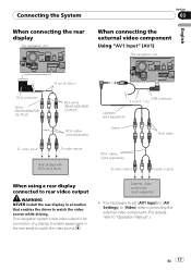
...seats to "Operation Manual".) En 17 Connecting the System When connecting the rear display The navigation unit Section 03 When connecting the external video component Using "AV1 Input" (AV1) The navigation unit English RCA connector Yellow (REAR MONITOR OUTPUT) 15 cm (5-7/8 in.) Red, white (REAR... MONITOR OUTPUT) To video input RCA cables (sold separately) To audio inputs Rear display with RCA input jacks USB connector 2 m (6 ft. 7 in.) CD-RM10 (sold separately) ...
...seats to "Operation Manual".) En 17 Connecting the System When connecting the rear display The navigation unit Section 03 When connecting the external video component Using "AV1 Input" (AV1) The navigation unit English RCA connector Yellow (REAR MONITOR OUTPUT) 15 cm (5-7/8 in.) Red, white (REAR... MONITOR OUTPUT) To video input RCA cables (sold separately) To audio inputs Rear display with RCA input jacks USB connector 2 m (6 ft. 7 in.) CD-RM10 (sold separately) ...
Installation Manual
Page 18
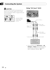
... video output To audio outputs External video component (sold separately) for wiring. If you use a CD-RM10 (sold separately) ! OK L VGR L RG V L : Left audio (White) R : Right audio (Red) V : Video (Yellow) G : Ground Using "AV2 Input" (AV2) The navigation unit RCA connector Yellow (VIDEO INPUT) 20 cm (7-7/8 in [AV Settings] to [Video] when connecting the...
... video output To audio outputs External video component (sold separately) for wiring. If you use a CD-RM10 (sold separately) ! OK L VGR L RG V L : Left audio (White) R : Right audio (Red) V : Video (Yellow) G : Ground Using "AV2 Input" (AV2) The navigation unit RCA connector Yellow (VIDEO INPUT) 20 cm (7-7/8 in [AV Settings] to [Video] when connecting the...

Installation Manual
Page 19
It is necessary to "Operation Manual".) English Section 03 En 19 Connecting the System When connecting the external unit featuring video source The navigation unit Blue RCA connector Yellow (VIDEO INPUT) 20 cm (7-7/8 in [AV Settings] to [EXT] when connecting the external unit. (For details, refer to set [AV2 Input] in .) IP-BUS cable (sold separately) Black RCA cable (sold separately) To IP-BUS output To video output Pioneer external unit (sold separately) !
It is necessary to "Operation Manual".) English Section 03 En 19 Connecting the System When connecting the external unit featuring video source The navigation unit Blue RCA connector Yellow (VIDEO INPUT) 20 cm (7-7/8 in [AV Settings] to [EXT] when connecting the external unit. (For details, refer to set [AV2 Input] in .) IP-BUS cable (sold separately) Black RCA cable (sold separately) To IP-BUS output To video output Pioneer external unit (sold separately) !
Installation Manual
Page 21
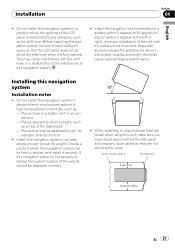
...otherwise cause reduced display performance. Before installing this navigation system, be sure to leave sufficient space so that may become subject to bear its weight. Choose a position where this navigation system is fully opened. Install the navigation unit horizontally on top of the LCD panel is ...obstructed by rain, for errors in .) En 21 Improper installation of the unit with the shift lever, or a malfunction of ...
...otherwise cause reduced display performance. Before installing this navigation system, be sure to leave sufficient space so that may become subject to bear its weight. Choose a position where this navigation system is fully opened. Install the navigation unit horizontally on top of the LCD panel is ...obstructed by rain, for errors in .) En 21 Improper installation of the unit with the shift lever, or a malfunction of ...

Installation Manual
Page 22
...up the area shown in the way, bend it overheats, so don't install the navigation unit anywhere hot -for instance, near a heater outlet. Installation using the screw holes on the shape of the navigation unit % Fastening the navigation unit to dissipate heat. Use either the binding screws (5 mm × 8 mm) ...or flush surface screws (5 mm × 8 mm), depending on the side of the bracket's screw holes. Position the navigation unit so that the brackets screw holes and its screw holes are aligned (are fitted), and tighten the screws at 3 or 4 locations on each side. ...
...up the area shown in the way, bend it overheats, so don't install the navigation unit anywhere hot -for instance, near a heater outlet. Installation using the screw holes on the shape of the navigation unit % Fastening the navigation unit to dissipate heat. Use either the binding screws (5 mm × 8 mm) ...or flush surface screws (5 mm × 8 mm), depending on the side of the bracket's screw holes. Position the navigation unit so that the brackets screw holes and its screw holes are aligned (are fitted), and tighten the screws at 3 or 4 locations on each side. ...


