Owner's Manual
Page 2
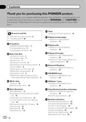
... manual before using this ! Be sure to read and observe WARNINGs and CAUTIONs in this unit 7 Operating environment 8 After-sales service for Pioneer products 8 Visit our website 8 Protecting your unit from theft 8 Resetting the microprocessor 9 Feature demo mode 9 Adjusting the response positions of ...the touch panels (Touch Panel Calibration) 9 What's what Head unit 10 Optional remote control 10 Basic Operations Basic Operations 11 Operating the scroll bar and the scrubber bar 12 Activating the touch panel keys 13 Common operations...
... manual before using this ! Be sure to read and observe WARNINGs and CAUTIONs in this unit 7 Operating environment 8 After-sales service for Pioneer products 8 Visit our website 8 Protecting your unit from theft 8 Resetting the microprocessor 9 Feature demo mode 9 Adjusting the response positions of ...the touch panels (Touch Panel Calibration) 9 What's what Head unit 10 Optional remote control 10 Basic Operations Basic Operations 11 Operating the scroll bar and the scrubber bar 12 Activating the touch panel keys 13 Common operations...
Owner's Manual
Page 10
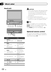
...For details concerning operations, see the remote control manual. 10 En Use an optional Pioneer USB cable (CD-U50E) to connect the USB audio player/USB memory as any device connected directly to the normal display. For details on . Part MUTE/ 1 ( : AVH-P5200BT only) MENU Displaying the 2 ...menu. Auto EQ microphone input jack a Use to its operation manual. Press MODE and hold to connect an auxiliary device. mation display off . c RESET d SD memory card slot Optional remote control The remote control CD-R55 is connected, press...
...For details concerning operations, see the remote control manual. 10 En Use an optional Pioneer USB cable (CD-U50E) to connect the USB audio player/USB memory as any device connected directly to the normal display. For details on . Part MUTE/ 1 ( : AVH-P5200BT only) MENU Displaying the 2 ...menu. Auto EQ microphone input jack a Use to its operation manual. Press MODE and hold to connect an auxiliary device. mation display off . c RESET d SD memory card slot Optional remote control The remote control CD-R55 is connected, press...

Owner's Manual
Page 31
... to this unit. ! Touch and hold for the Auto/manual setting. tooth Device) address on page 53. Refer to this manual. ! AVRCP profile (Audio/Video Remote Control Profile): You can only operate Fader/Balance (balance adjustment) in progress on this unit is set for more 9 than two seconds to Setting automatic...
... to this unit. ! Touch and hold for the Auto/manual setting. tooth Device) address on page 53. Refer to this manual. ! AVRCP profile (Audio/Video Remote Control Profile): You can only operate Fader/Balance (balance adjustment) in progress on this unit is set for more 9 than two seconds to Setting automatic...

Owner's Manual
Page 72
... your system. Appendix Additional Information Troubleshooting Common Symptom Cause Action (Reference page) The power will not turn on this video tible with the remote control is blown. Leads and con- The fuse is not possible. sor to ACC). Operation with your display. (Page 59) The ...ignition switch is turned ON (or is not Firmly secure the video skip. The unit does not operate correctly even when the appropriate remote control buttons are above recom- Some operations are prohibited with another disc. Try operating with certain discs. Playback is not The disc...
... your system. Appendix Additional Information Troubleshooting Common Symptom Cause Action (Reference page) The power will not turn on this video tible with the remote control is blown. Leads and con- The fuse is not possible. sor to ACC). Operation with your display. (Page 59) The ...ignition switch is turned ON (or is not Firmly secure the video skip. The unit does not operate correctly even when the appropriate remote control buttons are above recom- Some operations are prohibited with another disc. Try operating with certain discs. Playback is not The disc...

Installation Manual
Page 3
... the auto antenna. Vehicles with cable clamps or adhesive tape. Wrap adhesive tape around wiring that the ground wire is properly connected to the system remote control of an external power amp or the vehicle's auto-antenna relay control terminal (max. 300 mA 12 V DC). Never cut the insulation of the...
... the auto antenna. Vehicles with cable clamps or adhesive tape. Wrap adhesive tape around wiring that the ground wire is properly connected to the system remote control of an external power amp or the vehicle's auto-antenna relay control terminal (max. 300 mA 12 V DC). Never cut the insulation of the...
Installation Manual
Page 4
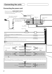
...speaker or Subwoofer (4 Ω) When using a subwoofer of this unit. Connecting the units Connecting the power cord Wired remote input (WIRED REMOTE INPUT) Hard-wired remote control adaptor can be sure to connect with Violet and Violet/black leads of 70 W (2 Ω), be connected (...937;) × 2 4 Red Connect to the constant 12 V supply terminal. Green Not used. Microphone (supplied) (AVH-P5200BT only) 17 cm (6-3/4 in.) 17 cm (6-3/4 in.) RGB input Microphone input Jack (MIC) (AVH-5200BT only) IP-BUS input (Blue) 4 m (13 ft. 1 in.) This product Fuse (10 A) Yellow ...
...speaker or Subwoofer (4 Ω) When using a subwoofer of this unit. Connecting the units Connecting the power cord Wired remote input (WIRED REMOTE INPUT) Hard-wired remote control adaptor can be sure to connect with Violet and Violet/black leads of 70 W (2 Ω), be connected (...937;) × 2 4 Red Connect to the constant 12 V supply terminal. Green Not used. Microphone (supplied) (AVH-P5200BT only) 17 cm (6-3/4 in.) 17 cm (6-3/4 in.) RGB input Microphone input Jack (MIC) (AVH-5200BT only) IP-BUS input (Blue) 4 m (13 ft. 1 in.) This product Fuse (10 A) Yellow ...

Installation Manual
Page 6
...) To rear output Subwoofer output (SUBWOOFER OUTPUT) To front output 17 cm (6-3/4 in.) To subwoofer output This product Connect with RCA cables (sold separately) System remote control Left Right Subwoofer Subwoofer Front speaker Rear speaker Perform these connections when using the optional amplifier...
...) To rear output Subwoofer output (SUBWOOFER OUTPUT) To front output 17 cm (6-3/4 in.) To subwoofer output This product Connect with RCA cables (sold separately) System remote control Left Right Subwoofer Subwoofer Front speaker Rear speaker Perform these connections when using the optional amplifier...

Installation Manual
Page 8
Connecting the system Wired remote input (WIRED REMOTE INPUT) Hard-wired remote control adaptor can be connected (sold separately). WARNING Never install the display in a location where it is necessary to the driver while driving. CD-BTB200) (sold separately) (AVH-P5200DVD only) This product IP-BUS input IP-BUS cable (Supplied with RCA input jacks...
Connecting the system Wired remote input (WIRED REMOTE INPUT) Hard-wired remote control adaptor can be connected (sold separately). WARNING Never install the display in a location where it is necessary to the driver while driving. CD-BTB200) (sold separately) (AVH-P5200DVD only) This product IP-BUS input IP-BUS cable (Supplied with RCA input jacks...


