Owner's Manual
Page 4
... functions Adjusting the response positions of the touch panels (Touch Panel Calibration) 75 Using an AUX source 75 Using an external unit 76 Installation Connecting the units 77 Installation 87 Additional information Troubleshooting 90 Error messages 92 Understanding auto EQ error messages 96 Understanding messages 96 Indicator list 97 Handling guidelines 99...
... functions Adjusting the response positions of the touch panels (Touch Panel Calibration) 75 Using an AUX source 75 Using an external unit 76 Installation Connecting the units 77 Installation 87 Additional information Troubleshooting 90 Error messages 92 Understanding auto EQ error messages 96 Understanding messages 96 Indicator list 97 Handling guidelines 99...
Owner's Manual
Page 5
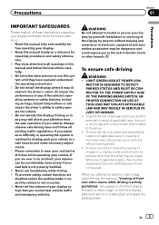
.... 7 Please remember to wear your seat belt at all times while operating your vehicle in a safe place and apply the parking brake. Installation or servicing of the display by persons without training and experience in this manual and follow all of electric shock or other persons to use...the risk of accident and the potential violation of applicable laws, no viewing of images on the front display. WARNING Do not attempt to install or service your display and retain them for operating procedures and safety information. 3 Pay close attention to all warnings in electronic equipment and ...
.... 7 Please remember to wear your seat belt at all times while operating your vehicle in a safe place and apply the parking brake. Installation or servicing of the display by persons without training and experience in this manual and follow all of electric shock or other persons to use...the risk of accident and the potential violation of applicable laws, no viewing of images on the front display. WARNING Do not attempt to install or service your display and retain them for operating procedures and safety information. 3 Pay close attention to all warnings in electronic equipment and ...
Owner's Manual
Page 6
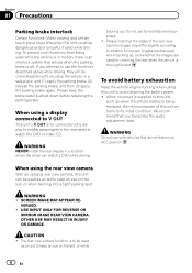
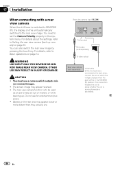
..., they will become disabled until you transcribe the audio adjustment data. USE INPUT ONLY FOR REVERSE OR MIRROR IMAGE REAR VIEW CAMERA. WARNING ! WARNING NEVER install the rear display in a safe place, and (1) apply the parking brake, (2) release the parking brake, and then (3) apply the parking brake again. If you attempt...
..., they will become disabled until you transcribe the audio adjustment data. USE INPUT ONLY FOR REVERSE OR MIRROR IMAGE REAR VIEW CAMERA. WARNING ! WARNING NEVER install the rear display in a safe place, and (1) apply the parking brake, (2) release the parking brake, and then (3) apply the parking brake again. If you attempt...
Owner's Manual
Page 7
Before you start Section 02 Before you start FCC ID: AJDK044 MODEL NO.: AVH-P4400BH/AVH-P3400BH/ AVH-P2400BT IC: 775E-K044 This device complies with Part 15 of RF energy that it deemed to comply without appropriate authorization may not cause ... of this equipment does cause harmful interference to radio or television reception, which the receiver is no guarantee that interference will not occur in a residential installation. These limits are designed to radio communications. However, there is connected. - Connect the equipment into an outlet on , the user is subject to ...
Before you start Section 02 Before you start FCC ID: AJDK044 MODEL NO.: AVH-P4400BH/AVH-P3400BH/ AVH-P2400BT IC: 775E-K044 This device complies with Part 15 of RF energy that it deemed to comply without appropriate authorization may not cause ... of this equipment does cause harmful interference to radio or television reception, which the receiver is no guarantee that interference will not occur in a residential installation. These limits are designed to radio communications. However, there is connected. - Connect the equipment into an outlet on , the user is subject to ...
Owner's Manual
Page 10
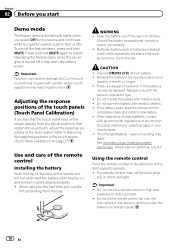
... the response positions of the touch panels (Touch Panel Calibration) If you select Off for a month or longer. ! Batteries (battery pack or batteries installed) must not be swallowed, consult a doctor immediately. ! Remove the battery if the remote control is a danger of children. Do not handle the battery...the battery be exposed to Adjusting the response positions of the touch panels (Touch Panel Calibration) on the back of the remote control Installing the battery Slide the tray on page 75. Important ! Use and care of the remote control out and insert the battery with ...
... the response positions of the touch panels (Touch Panel Calibration) If you select Off for a month or longer. ! Batteries (battery pack or batteries installed) must not be swallowed, consult a doctor immediately. ! Remove the battery if the remote control is a danger of children. Do not handle the battery...the battery be exposed to Adjusting the response positions of the touch panels (Touch Panel Calibration) on the back of the remote control Installing the battery Slide the tray on page 75. Important ! Use and care of the remote control out and insert the battery with ...
Owner's Manual
Page 30
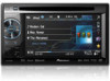
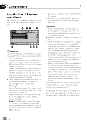
... by any of the following: compatibility issues with Pandora. ! Note: If the Data Plan for purposes of allowing your iPod which was installed the Pandora application. 8 12 3 Pandora S.Rtrv Abcdeabcdeabcdeabcde Abcdeabcdeabcdeabcde Abcdeabcdeabcdeabcde Abcdeabcdeabcdeabcde Wed 28 May 12:45 PM 01:45 7 -02:45 ...654 Important Requirements to access the Pandora music service using the Pioneer car audio/video products: ! changes to the Pandora music service by connecting your iPhone does not provide for the iPhone). ! Certain...
... by any of the following: compatibility issues with Pandora. ! Note: If the Data Plan for purposes of allowing your iPod which was installed the Pandora application. 8 12 3 Pandora S.Rtrv Abcdeabcdeabcdeabcde Abcdeabcdeabcdeabcde Abcdeabcdeabcdeabcde Abcdeabcdeabcdeabcde Wed 28 May 12:45 PM 01:45 7 -02:45 ...654 Important Requirements to access the Pandora music service using the Pioneer car audio/video products: ! changes to the Pandora music service by connecting your iPhone does not provide for the iPhone). ! Certain...
Owner's Manual
Page 31
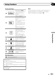
... equalizer curves. Refer to Indicator list on the iPod. En 31 Touch and hold for the track currently playing. Giving a "Thumbs-up the Pandora application installed on page 97. Refer to Using the autoequalizer on page 48. Using Pandoraâ Section 10 Using Pandoraâ Touch panel keys 1 2 3 4 5 Switching the S.Rtrv...
... equalizer curves. Refer to Indicator list on the iPod. En 31 Touch and hold for the track currently playing. Giving a "Thumbs-up the Pandora application installed on page 97. Refer to Using the autoequalizer on page 48. Using Pandoraâ Section 10 Using Pandoraâ Touch panel keys 1 2 3 4 5 Switching the S.Rtrv...
Owner's Manual
Page 67
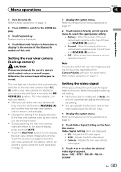
... turn the rear view camera off . Touch the source icon again to the rear view camera video (R.C IN) when a rear view camera is installed on your dealer.) ! When a rear view camera is initially set to Basic operations on the function menu. Refer to Auto, the unit will ...Setting the video signal When you are displayed. ! Camera - Setting the rear view camera (back up the rear view camera set up camera) CAUTION Pioneer recommends the use of this setting if the display switches to select the appropriate setting. ! For details, refer to Selecting a source using the touch...
... turn the rear view camera off . Touch the source icon again to the rear view camera video (R.C IN) when a rear view camera is installed on your dealer.) ! When a rear view camera is initially set to Basic operations on the function menu. Refer to Auto, the unit will ...Setting the video signal When you are displayed. ! Camera - Setting the rear view camera (back up the rear view camera set up camera) CAUTION Pioneer recommends the use of this setting if the display switches to select the appropriate setting. ! For details, refer to Selecting a source using the touch...

Owner's Manual
Page 75
...automatically recognized as the CD-V150M), you can enjoy the video contents of the connected iPod. ! Refer to What's what on page 11. Refer to Installation on page 77. There are two adjustment methods: 4-point adjustment, in order for the adjusted position is saved. # Do not turn off the engine ... and hold HOME to this unit via 3.5 mm plug (4 pole) cable (such as an AUX source and is assigned to be connected to your local Pioneer dealer. 1 Turn the unit off the engine while the data is con- The 16-point touch panel adjustment screen appears. # To cancel the adjustment,...
...automatically recognized as the CD-V150M), you can enjoy the video contents of the connected iPod. ! Refer to What's what on page 11. Refer to Installation on page 77. There are two adjustment methods: 4-point adjustment, in order for the adjusted position is saved. # Do not turn off the engine ... and hold HOME to this unit via 3.5 mm plug (4 pole) cable (such as an AUX source and is assigned to be connected to your local Pioneer dealer. 1 Turn the unit off the engine while the data is con- The 16-point touch panel adjustment screen appears. # To cancel the adjustment,...
Owner's Manual
Page 77
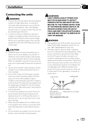
...POWER AMP Other devices Metal parts of the vehicle, such as the shift lever, parking brake or seat sliding mechanism. ! Installation Section 17 Installation Connecting the units WARNING ! To avoid the risk of accident and the potential violation of applicable laws, no viewing of electric ...! Do not shorten any bare wiring to allow any cables. Make sure that cables will not obstruct driving. ! When installing this unit. ! PIONEER does not recommend that it could result in a location where they must be in fire, generation of the display unit to authorized...
...POWER AMP Other devices Metal parts of the vehicle, such as the shift lever, parking brake or seat sliding mechanism. ! Installation Section 17 Installation Connecting the units WARNING ! To avoid the risk of accident and the potential violation of applicable laws, no viewing of electric ...! Do not shorten any bare wiring to allow any cables. Make sure that cables will not obstruct driving. ! When installing this unit. ! PIONEER does not recommend that it could result in a location where they must be in fire, generation of the display unit to authorized...
Owner's Manual
Page 78
...of an external power amp. When this unit with a glass anten- Never connect the blue/white cable to connect connectors of the battery before installation. - Be sure to the power terminal of the rating prescribed. - Disconnect the negative terminal of the same color. 78 En IP-BUS... other devices. Never wire the negative speaker cable directly to protect the wiring. - To prevent a short-circuit, overheating or malfunction, be installed in a fire or malfunction. ! Do not connect the yellow cable to the battery by passing it to the power terminal of this cable...
...of an external power amp. When this unit with a glass anten- Never connect the blue/white cable to connect connectors of the battery before installation. - Be sure to the power terminal of the rating prescribed. - Disconnect the negative terminal of the same color. 78 En IP-BUS... other devices. Never wire the negative speaker cable directly to protect the wiring. - To prevent a short-circuit, overheating or malfunction, be installed in a fire or malfunction. ! Do not connect the yellow cable to the battery by passing it to the power terminal of this cable...

Owner's Manual
Page 79
Installation Section 17 Installation En 79
Installation Section 17 Installation En 79
Owner's Manual
Page 80
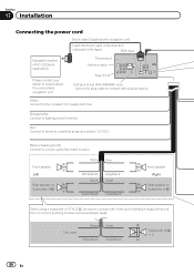
Do not connect anything to terminal controlled by ignition switch (12 V DC). Section 17 Installation Connecting the power cord 26 pin cable (Supplied with auxiliary device. Red Connect to Green and Green/black leads. Not used. Orange/white Connect ...connectable navigation unit. Green Green/black Violet Violet/black Subwoofer (4 Ω) × 2 80 En This product Antenna input Fuse (10 A) AUX jack (3.5 ø) (AVH-P4400BH only) Use a mini plug cable to connect with navigation unit) Insert the 26 pin cable in the direction indicated in the figure.
Do not connect anything to terminal controlled by ignition switch (12 V DC). Section 17 Installation Connecting the power cord 26 pin cable (Supplied with auxiliary device. Red Connect to Green and Green/black leads. Not used. Orange/white Connect ...connectable navigation unit. Green Green/black Violet Violet/black Subwoofer (4 Ω) × 2 80 En This product Antenna input Fuse (10 A) AUX jack (3.5 ø) (AVH-P4400BH only) Use a mini plug cable to connect with navigation unit) Insert the 26 pin cable in the direction indicated in the figure.
Owner's Manual
Page 81
.... Connection method 1. En 81 This lead must be connected (sold separately). Clamp firmly with Mute function, wire this unit. Installation Section 17 Installation 4 m (13 ft. 1 in.) Microphone (AVH-P4400BH/AVH-P3400BH/AVH-P2400BT only) Microphone input (AVH-P4400BH/AVH-P3400BH/AVH-P2400BT only) Wired remote input Hard-wired remote control adaptor can be connected to the power supply side of...
.... Connection method 1. En 81 This lead must be connected (sold separately). Clamp firmly with Mute function, wire this unit. Installation Section 17 Installation 4 m (13 ft. 1 in.) Microphone (AVH-P4400BH/AVH-P3400BH/AVH-P2400BT only) Microphone input (AVH-P4400BH/AVH-P3400BH/AVH-P2400BT only) Wired remote input Hard-wired remote control adaptor can be connected to the power supply side of...
Owner's Manual
Page 82
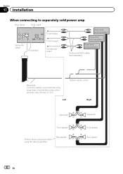
... Rear speaker Perform these connections when using the optional amplifier. Front speaker Rear speaker 82 En Section 17 Installation When connecting to separately sold power amp Rear output Front output Subwoofer output This product To rear output To front output To subwoofer output Power...
... Rear speaker Perform these connections when using the optional amplifier. Front speaker Rear speaker 82 En Section 17 Installation When connecting to separately sold power amp Rear output Front output Subwoofer output This product To rear output To front output To subwoofer output Power...
Owner's Manual
Page 83
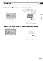
Installation Connecting the system (for AVH-P1400DVD model) This product Microphone for AVH-P2400BT/AVH-P1400DVD model) This product HD Radio tuner (sold separately) Section 17 Installation IP-BUS input Black IP-BUS cable (Supplied with Bluetooth adapter) Connecting the system (for hands-free phoning (supplied with HD Radio tuner) En 83 CD-BTB200) (sold separately) IP-BUS input IP-BUS cable (Supplied with Bluetooth adapter) Bluetooth adapter (e.g.
Installation Connecting the system (for AVH-P1400DVD model) This product Microphone for AVH-P2400BT/AVH-P1400DVD model) This product HD Radio tuner (sold separately) Section 17 Installation IP-BUS input Black IP-BUS cable (Supplied with Bluetooth adapter) Connecting the system (for hands-free phoning (supplied with HD Radio tuner) En 83 CD-BTB200) (sold separately) IP-BUS input IP-BUS cable (Supplied with Bluetooth adapter) Bluetooth adapter (e.g.
Owner's Manual
Page 84
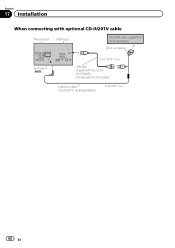
Section 17 Installation When connecting with optional CD-IU201V cable This product USB input iPod with this unit for AVH-P4400BH. Sold separately for other models.) Interface cable (CD-IU201V) (sold separately) 2 m (6 ft. 7 in .) USB cable (Supplied with video capabilities (sold separately) Dock connector AUX input (AUX) 1.5 m (4 ft. 11 in .) 84 En
Section 17 Installation When connecting with optional CD-IU201V cable This product USB input iPod with this unit for AVH-P4400BH. Sold separately for other models.) Interface cable (CD-IU201V) (sold separately) 2 m (6 ft. 7 in .) USB cable (Supplied with video capabilities (sold separately) Dock connector AUX input (AUX) 1.5 m (4 ft. 11 in .) 84 En
Owner's Manual
Page 85
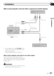
...menu when connecting the external video component. Refer to watch the DVD, etc. En 85 WARNING ! Installation Section 17 When connecting the external video component and the display External video component (sold separately) Installation Audio inputs (L IN, R IN) To audio outputs To video output Video input (V IN) RCA...output This product's rear video output and rear audio output are for connection of a display to the driver while driving. Never install the display in a location where it is necessary to change AV Input in the rear seats to Setting AV input on page 64.
...menu when connecting the external video component. Refer to watch the DVD, etc. En 85 WARNING ! Installation Section 17 When connecting the external video component and the display External video component (sold separately) Installation Audio inputs (L IN, R IN) To audio outputs To video output Video input (V IN) RCA...output This product's rear video output and rear audio output are for connection of a display to the driver while driving. Never install the display in a location where it is necessary to change AV Input in the rear seats to Setting AV input on page 64.
Owner's Manual
Page 86
... the two lead wires connected to Setting the rear view camera (back up . You must use for entertainment purposes. ! ror reversed images. ! CAUTION ! Section 17 Installation When connecting with a rear view camera When the shift lever is switched to REVERSE (R), the display on this unit automatically switches to set the Camera...
... the two lead wires connected to Setting the rear view camera (back up . You must use for entertainment purposes. ! ror reversed images. ! CAUTION ! Section 17 Installation When connecting with a rear view camera When the shift lever is switched to REVERSE (R), the display on this unit automatically switches to set the Camera...
Owner's Manual
Page 87
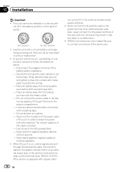
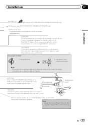
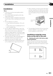
... where it may interfere with the screw holes of the bracket, and tighten the screws at an angle of the vehicle. - Installation Section 17 Installation Installation Notes ! Install this unit where: - To some types of vehicles, this unit cannot be damaged if it may cause injury to a passenger... (ii) impair the performance of any loose cables so they are aligned with operation of less than 30°. ! Do not use the optional installation kit (ADT-VA133). it may cause malfunctions. ! In such case, use unauthorized parts as near the heater outlet. ! Leave ample space 5 ...
... where it may interfere with the screw holes of the bracket, and tighten the screws at an angle of the vehicle. - Installation Section 17 Installation Installation Notes ! Install this unit where: - To some types of vehicles, this unit cannot be damaged if it may cause injury to a passenger... (ii) impair the performance of any loose cables so they are aligned with operation of less than 30°. ! Do not use the optional installation kit (ADT-VA133). it may cause malfunctions. ! In such case, use unauthorized parts as near the heater outlet. ! Leave ample space 5 ...


