Owner's Manual
Page 1
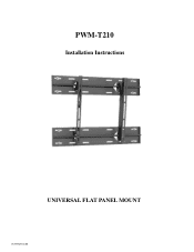
PWM-T210 Installation Instructions UNIVERSAL FLAT PANEL MOUNT IN-PWMT210.R0
PWM-T210 Installation Instructions UNIVERSAL FLAT PANEL MOUNT IN-PWMT210.R0
Owner's Manual
Page 2
PWM-T210 TABLE OF CONTENTS Warning Statements 3 Parts List 4 Installation Tools 4 Locating the Center of the Display 5 Mounting Bracket Positioning 5 Securing the Mounting Brackets 6 Marking the Wall 7 Marking the Bottom Mounting Points 7 Securing the Lower Wall Plate 8 Securing the Upper Wall Plate 8 Mounting the Display 9 Securing the Display 10 Technical Specifications 11 Warranty 11 Contact Premier Mounts 11 Page 2 Installation Instructions
PWM-T210 TABLE OF CONTENTS Warning Statements 3 Parts List 4 Installation Tools 4 Locating the Center of the Display 5 Mounting Bracket Positioning 5 Securing the Mounting Brackets 6 Marking the Wall 7 Marking the Bottom Mounting Points 7 Securing the Lower Wall Plate 8 Securing the Upper Wall Plate 8 Mounting the Display 9 Securing the Display 10 Technical Specifications 11 Warranty 11 Contact Premier Mounts 11 Page 2 Installation Instructions
Owner's Manual
Page 3
...mounting. Failure to the wall studs. ma display display, contact the nearest dealer or Pioneer. All four (4) Lag bolts must be left in the area surrounding the plasma ...use specified parts for future reference. Warning Statements The wall or ceiling structure must be read and understood, including all of fire. The entire installation instructions should be taken at least five (5) times the weight of supporting at all of the safety symbols and safety precautions, before beginning installation. The installation instructions should always perform the installation...
...mounting. Failure to the wall studs. ma display display, contact the nearest dealer or Pioneer. All four (4) Lag bolts must be left in the area surrounding the plasma ...use specified parts for future reference. Warning Statements The wall or ceiling structure must be read and understood, including all of fire. The entire installation instructions should be taken at least five (5) times the weight of supporting at all of the safety symbols and safety precautions, before beginning installation. The installation instructions should always perform the installation...
Owner's Manual
Page 4
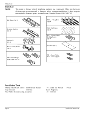
PWM-T210 Parts List NOTE: This mount is shipped with all installation hardware and components. Wall Plates (Qty 2) 5/16" x 3" Lag Bolts (Qty 8) Mounting Brackets (Qty 2) Griplates™ (Qty 6) M6 x 12 Safety ...Screws (Qty 4) Installation Tools Phillips Head Screw Driver Soft Material/ Blanket Tape Measure Drill Gun Stud Finder (Commercially Available) 1/2" Socket and Wrench Level (Supplied) 1/4" Drill Bit Pencil Page 4 Installation Instructions If there are missing and/ or damaged before beginning installation. Make sure that none of these parts are parts missing and/or ...
PWM-T210 Parts List NOTE: This mount is shipped with all installation hardware and components. Wall Plates (Qty 2) 5/16" x 3" Lag Bolts (Qty 8) Mounting Brackets (Qty 2) Griplates™ (Qty 6) M6 x 12 Safety ...Screws (Qty 4) Installation Tools Phillips Head Screw Driver Soft Material/ Blanket Tape Measure Drill Gun Stud Finder (Commercially Available) 1/2" Socket and Wrench Level (Supplied) 1/4" Drill Bit Pencil Page 4 Installation Instructions If there are missing and/ or damaged before beginning installation. Make sure that none of these parts are parts missing and/or ...
Owner's Manual
Page 5
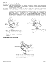
... LAY THE FLAT PANEL ON THE FLOOR WITHOUT ANY PROTECTION TO THE GLASS. AT LEAST (2) QUALIFIED PERSONNEL ARE STRONGLY RECOMMENDED FOR INSTALLATION OF THIS PRODUCT. FAILURE TO DO SO COULD RESULT IN SERIOUS INJURY AND POSSIBLE DAMAGE TO THE FLAT PANEL. Mounting Bracket Positioning Marking the Center... Out Figure 3 3. WARNING: INVERT THE FLAT PANEL PLACE IT ON A SOFT, FLAT SURFACE TO PREVENT DAMAGE TO THE FLAT PANEL. Installation Instructions Page 5 Using a pencil lightly mark the center of the Display Inverted Display CL Figure 2 2. FAILURE TO DO SO WILL RESULT IN DAMAGING THE FLAT PANEL...
... LAY THE FLAT PANEL ON THE FLOOR WITHOUT ANY PROTECTION TO THE GLASS. AT LEAST (2) QUALIFIED PERSONNEL ARE STRONGLY RECOMMENDED FOR INSTALLATION OF THIS PRODUCT. FAILURE TO DO SO COULD RESULT IN SERIOUS INJURY AND POSSIBLE DAMAGE TO THE FLAT PANEL. Mounting Bracket Positioning Marking the Center... Out Figure 3 3. WARNING: INVERT THE FLAT PANEL PLACE IT ON A SOFT, FLAT SURFACE TO PREVENT DAMAGE TO THE FLAT PANEL. Installation Instructions Page 5 Using a pencil lightly mark the center of the Display Inverted Display CL Figure 2 2. FAILURE TO DO SO WILL RESULT IN DAMAGING THE FLAT PANEL...
Owner's Manual
Page 6
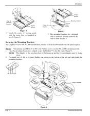
... DIMPLES FACING DOWN Page 6 Figure 6 Installation Instructions Pre-install two (2) M6 x 30 (mm) Phillips pan screws to the flat panel (Figure 6). Match the center of viewing guide with a center of viewing guide on the side of Display Mounting Bracket Viewing Guide Center Figure 4 4. NOTE: Your plasma uses M8 x 20 or M6 x 12 Phillips screws, use the M8, or M6, mounting points...
... DIMPLES FACING DOWN Page 6 Figure 6 Installation Instructions Pre-install two (2) M6 x 30 (mm) Phillips pan screws to the flat panel (Figure 6). Match the center of viewing guide with a center of viewing guide on the side of Display Mounting Bracket Viewing Guide Center Figure 4 4. NOTE: Your plasma uses M8 x 20 or M6 x 12 Phillips screws, use the M8, or M6, mounting points...
Owner's Manual
Page 7
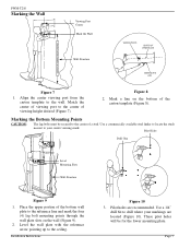
...plate. Pilot Holes Drill Gun 16" Wall Plate Level Mounting Slots Wall Structure Figure 9 1. Installation Instructions Figure 10 3. Align the center viewing port from the carton template to the ceiling. Use a 1/4" drill bit to the reference line and mark the four (4) lag bolt mounting ...the wall plate with the reference arrow pointing up to the wall. Match the center of viewing port to your markings are recommended. Mark a line on the wall (Figure 9). 2. Use a commercially available stud finder to locate the studs nearest to the center of the carton template (Figure 8).
...plate. Pilot Holes Drill Gun 16" Wall Plate Level Mounting Slots Wall Structure Figure 9 1. Installation Instructions Figure 10 3. Align the center viewing port from the carton template to the ceiling. Use a 1/4" drill bit to the reference line and mark the four (4) lag bolt mounting ...the wall plate with the reference arrow pointing up to the wall. Match the center of viewing port to your markings are recommended. Mark a line on the wall (Figure 9). 2. Use a commercially available stud finder to locate the studs nearest to the center of the carton template (Figure 8).
Owner's Manual
Page 8
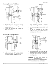
... pilot holes will be for the upper mounting bracket. Page 8 Figure 12 3. When the bottom wall plate is properly installed to the ceiling. 3. Secure the plate using the provided lag bolts and washers. Installation Instructions Lay the carton template on top of the wall plate. 5. CAUTION: Do not over tighten the mounting hardware. NOTE...
... pilot holes will be for the upper mounting bracket. Page 8 Figure 12 3. When the bottom wall plate is properly installed to the ceiling. 3. Secure the plate using the provided lag bolts and washers. Installation Instructions Lay the carton template on top of the wall plate. 5. CAUTION: Do not over tighten the mounting hardware. NOTE...
Owner's Manual
Page 9
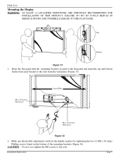
... TO THE FLAT PANEL. Top Bottom Figure 15 1. PWM-T210 Mounting the Display WARNING: AT LEAST (2) QUALIFIED PERSONNEL ARE STRONGLY RECOMMENDED FOR INSTALLATION OF THIS PRODUCT. Installation Instructions Page 9 Make any lateral shift adjustments and lock the display in place by tightening the two (2) M6 x 30 (mm) Phillips screws found on the bottom of the...
... TO THE FLAT PANEL. Top Bottom Figure 15 1. PWM-T210 Mounting the Display WARNING: AT LEAST (2) QUALIFIED PERSONNEL ARE STRONGLY RECOMMENDED FOR INSTALLATION OF THIS PRODUCT. Installation Instructions Page 9 Make any lateral shift adjustments and lock the display in place by tightening the two (2) M6 x 30 (mm) Phillips screws found on the bottom of the...
Owner's Manual
Page 10
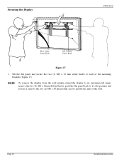
Page 10 Installation Instructions NOTE: To remove the display from the wall simply extend the display to its maximum tilt range, remove the two (2) M6 x 12mm Safety Knobs, push the flat panel back to each of the wall. Tilt the flat panel and secure the two (2) M6 x 12 mm safety knobs to it's flat position and loosen or remove the two (2) M6 x 30 lateral shift screws and lift the unit of the mounting brackets (Figure 17). Securing the Display PWM-T210 M6 x 12mm Safety Knob M6 x 12mm Safety Knob Figure 17 1.
Page 10 Installation Instructions NOTE: To remove the display from the wall simply extend the display to its maximum tilt range, remove the two (2) M6 x 12mm Safety Knobs, push the flat panel back to each of the wall. Tilt the flat panel and secure the two (2) M6 x 12 mm safety knobs to it's flat position and loosen or remove the two (2) M6 x 30 lateral shift screws and lift the unit of the mounting brackets (Figure 17). Securing the Display PWM-T210 M6 x 12mm Safety Knob M6 x 12mm Safety Knob Figure 17 1.
Owner's Manual
Page 11
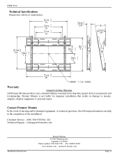
... Service - (800) 368-9700 Ext. 224 Technical Support - Anaheim CA 92806 Phone number: 800-368-9700 Fax: 800832-4888 www.mounts.com [email protected] Page 11 PWM-T210 Technical Specifications Dimensions shown in the completion of the installation. Premier Mounts is not liable for improper installation that results in materials and workmanship. [email protected] Installation Instructions...
... Service - (800) 368-9700 Ext. 224 Technical Support - Anaheim CA 92806 Phone number: 800-368-9700 Fax: 800832-4888 www.mounts.com [email protected] Page 11 PWM-T210 Technical Specifications Dimensions shown in the completion of the installation. Premier Mounts is not liable for improper installation that results in materials and workmanship. [email protected] Installation Instructions...


