
WVSF332 User Guide
Page 16
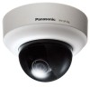
Do not use the connector for service. Major operating controls Dome cover Inner dome Clear dome (Provided only for service) Monitor out connector for service* Direction marker for installation Azimuth adjustment ring Monitor out connector for adjustment (RCA jack) Marker MONITOR OUT EXT FRONT TOP View from the side LOCK Panning lock screw [LOCK] Panning table BASE-T/ BASE TX TOP 12V IN Tilting table 12 V DC power supply terminal * This connector is provided only for checking the adjustment of the angular field of view on the video monitor. 16
Do not use the connector for service. Major operating controls Dome cover Inner dome Clear dome (Provided only for service) Monitor out connector for service* Direction marker for installation Azimuth adjustment ring Monitor out connector for adjustment (RCA jack) Marker MONITOR OUT EXT FRONT TOP View from the side LOCK Panning lock screw [LOCK] Panning table BASE-T/ BASE TX TOP 12V IN Tilting table 12 V DC power supply terminal * This connector is provided only for checking the adjustment of the angular field of view on the video monitor. 16

WVSF332 User Guide
Page 28
... 4 screws (M4, locally procured) Direction marker for further information about adjustment. • For wall mounting The camera shall be mounted with the "gFRONT" marker oriented to the desired shooting area. Adjustment of panning. Refer to the "Adjustment" section (☞ pages 29 to 33) for installation MONITOOURT 4 FTROOPNT EXT 3 ...conducted after turning off each device. z Detach the dome cover. (☞ Page 18) x Connect the cables to the camera. (☞ Pages 23 to 27) As necessary, use a cable tie (accessory) to ensure that the cables does not tangle the cables.
... 4 screws (M4, locally procured) Direction marker for further information about adjustment. • For wall mounting The camera shall be mounted with the "gFRONT" marker oriented to the desired shooting area. Adjustment of panning. Refer to the "Adjustment" section (☞ pages 29 to 33) for installation MONITOOURT 4 FTROOPNT EXT 3 ...conducted after turning off each device. z Detach the dome cover. (☞ Page 18) x Connect the cables to the camera. (☞ Pages 23 to 27) As necessary, use a cable tie (accessory) to ensure that the cables does not tangle the cables.

WVSF332 User Guide
Page 29
... position markers K TOP BASE-T/ BASE TX 12V=IN Clockwise panning end marker: (Rotation within the range of view. Adjustment z Adjust the camera angle. Horizontal position (Panning) Loosen the panning lock screw, rotate the panning table to fix the tilting table. (Recommended tightening torque:... it is rotated to change the angular field of 180 ° (when panning clockwise) and 170 ° (when panning counterclockwise). When determining the camera angle, repeat fine adjustments by gradually moving the panning table, tilting table, and azimuth adjustment ring. Horizontal: 27.7 ° ...
... position markers K TOP BASE-T/ BASE TX 12V=IN Clockwise panning end marker: (Rotation within the range of view. Adjustment z Adjust the camera angle. Horizontal position (Panning) Loosen the panning lock screw, rotate the panning table to fix the tilting table. (Recommended tightening torque:... it is rotated to change the angular field of 180 ° (when panning clockwise) and 170 ° (when panning counterclockwise). When determining the camera angle, repeat fine adjustments by gradually moving the panning table, tilting table, and azimuth adjustment ring. Horizontal: 27.7 ° ...