
Dvd Theater Receiver
Page 2
...HT730 SA-HT730 SB-FS730 SB-PC730 SB-FS731 SB-WA730 SC-HT733 SA-HT733 SB-FS730 SB-PC730 SB-FS731 SB-WA733 SC-HT930 SA-HT930 SB-FS930 SB-PC930 SB-FS931 SB-WA930 SC-HT933 SA... and safety, please read these instructions are described mainly with Part 15 of North America One Panasonic Way Secaucus, NJ 07094 Telephone No.: 1-800-211-7262 THE FOLLOWING APPLIES ONLY IN THE...to operate this equipment does cause harmful interference to radio or television reception, which the receiver is different according to Part 15 of electric shock to provide reasonable protection against harmful ...
...HT730 SA-HT730 SB-FS730 SB-PC730 SB-FS731 SB-WA730 SC-HT733 SA-HT733 SB-FS730 SB-PC730 SB-FS731 SB-WA733 SC-HT930 SA-HT930 SB-FS930 SB-PC930 SB-FS931 SB-WA930 SC-HT933 SA... and safety, please read these instructions are described mainly with Part 15 of North America One Panasonic Way Secaucus, NJ 07094 Telephone No.: 1-800-211-7262 THE FOLLOWING APPLIES ONLY IN THE...to operate this equipment does cause harmful interference to radio or television reception, which the receiver is different according to Part 15 of electric shock to provide reasonable protection against harmful ...

Technical Guide
Page 2
... a product. Prepared by Herb Chin, & Joe Blanks Panasonic Services Company National Training Panasonic is a registered trademark of Panasonic North America "HDMI, the HDMI logo and High-Definition Multimedia... Interface are registered trademarks or trademarks of BBE Sound, Inc. Warning This service information is designed for experienced repair technicians only and is a registered trademark of potential dangers in attempting to advise non-technical individuals of Digital Theater Systems Corporation. SA-HT730...
... a product. Prepared by Herb Chin, & Joe Blanks Panasonic Services Company National Training Panasonic is a registered trademark of Panasonic North America "HDMI, the HDMI logo and High-Definition Multimedia... Interface are registered trademarks or trademarks of BBE Sound, Inc. Warning This service information is designed for experienced repair technicians only and is a registered trademark of potential dangers in attempting to advise non-technical individuals of Digital Theater Systems Corporation. SA-HT730...
Technical Guide
Page 3
... 22 How to System Control IC2018 for Shutdown Problems 15 Control Unit Protection Concept 16 SUBWOOFER UNIT REPAIR (SB-WA730 / SA-WA930 17 Subwoofer Repair Strategy - POWER-ON START-UP SEQUENCE - WHERE IS THE PROBLEM 5 2. SENSOR TESTING ...10 ...of Contents OBJECTIVE...4 I NO START-UP AND DVD TRANSPORT PROBLEMS 5 1. TRAY INSTALLATION (AFTER REPAIRS 9 6. SIMULATED FAILURE SYMPTOMS - SENSORS, BELTS, AND MOTOR LOCATION 6 3. ALL THE SHUTDOWN POSSIBILITIES 12 Overall Repair Strategy 12 CONTROL UNIT REPAIR (SA-HT730 / SA-HT930) STRATEGY 13 Control unit repair Procedure 14...
... 22 How to System Control IC2018 for Shutdown Problems 15 Control Unit Protection Concept 16 SUBWOOFER UNIT REPAIR (SB-WA730 / SA-WA930 17 Subwoofer Repair Strategy - POWER-ON START-UP SEQUENCE - WHERE IS THE PROBLEM 5 2. SENSOR TESTING ...10 ...of Contents OBJECTIVE...4 I NO START-UP AND DVD TRANSPORT PROBLEMS 5 1. TRAY INSTALLATION (AFTER REPAIRS 9 6. SIMULATED FAILURE SYMPTOMS - SENSORS, BELTS, AND MOTOR LOCATION 6 3. ALL THE SHUTDOWN POSSIBILITIES 12 Overall Repair Strategy 12 CONTROL UNIT REPAIR (SA-HT730 / SA-HT930) STRATEGY 13 Control unit repair Procedure 14...
Technical Guide
Page 4
Objective This technical guide was prepared with the following objectives in mind: • Provide the servicer with a brief overview of the concepts of operation for new circuits employed in this line of models. • Provide drawings with emphasis on signal path to simplify the task of signal tracing and to locate the cause of a defect. • Furnish troubleshooting procedures that contribute to a speedier repair of the product. • Provide examples of typical problems that may have occurred in similar types of circuits. SA-HT730 / SAHT930 4
Objective This technical guide was prepared with the following objectives in mind: • Provide the servicer with a brief overview of the concepts of operation for new circuits employed in this line of models. • Provide drawings with emphasis on signal path to simplify the task of signal tracing and to locate the cause of a defect. • Furnish troubleshooting procedures that contribute to a speedier repair of the product. • Provide examples of typical problems that may have occurred in similar types of circuits. SA-HT730 / SAHT930 4
Technical Guide
Page 5
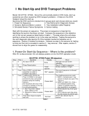
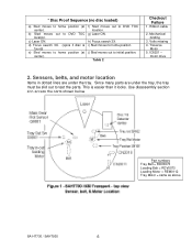
... is not open) 1. Time 0 0 1 sec 4 sec 5 sec 8 sec. 17 SA-HT730 / HT930 Power ON sequence Operation Display Proof AC input. Contacts are often caused by DVD transport problems - S9102 detects tray motor gear Slow rotation is divided into 6 groups (pick and... is already in the DVD transport stops the start -up . I No Start-Up and DVD Transport Problems Model: SA-HT730 / HT930. Step 1. 2. 3. 4. 5. 6. 7. Press Power button Disc # 1-5 light in DVD mode, start up symptoms are open / tray and into the DVD operation mode. Table 1 SA-HT730 / SAHT930 5 A ...
... is not open) 1. Time 0 0 1 sec 4 sec 5 sec 8 sec. 17 SA-HT730 / HT930 Power ON sequence Operation Display Proof AC input. Contacts are often caused by DVD transport problems - S9102 detects tray motor gear Slow rotation is divided into 6 groups (pick and... is already in the DVD transport stops the start -up . I No Start-Up and DVD Transport Problems Model: SA-HT730 / HT930. Step 1. 2. 3. 4. 5. 6. 7. Press Power button Disc # 1-5 light in DVD mode, start up symptoms are open / tray and into the DVD operation mode. Table 1 SA-HT730 / SAHT930 5 A ...
Technical Guide
Page 6
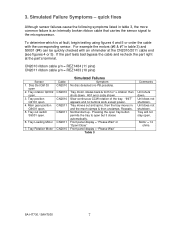
i) Sled moves to home position j) Sled moves out to DVD TOC location. Table 2 Checkout Failure 1. Mechanical binding 3. Sensors, belts, and motor location Items in dotted lines are under the tray. This is found) e) Sled moves ... tray must be slid out to test the parts. Part numbers Tray Belt = RDV0073 Loading Belt = RDV0073 Loading Motor = REM0112 Tray Motor = same as above SA-HT730 / SAHT930 6 * Disc Proof Sequence (no disc loaded) a) Sled moves to home position (at center). d) Focus search 3X. (spins if disc is easier than it looks...
i) Sled moves to home position j) Sled moves out to DVD TOC location. Table 2 Checkout Failure 1. Mechanical binding 3. Sensors, belts, and motor location Items in dotted lines are under the tray. This is found) e) Sled moves ... tray must be slid out to test the parts. Part numbers Tray Belt = RDV0073 Loading Belt = RDV0073 Loading Motor = REM0112 Tray Motor = same as above SA-HT730 / SAHT930 6 * Disc Proof Sequence (no disc loaded) a) Sled moves to home position (at center). d) Focus search 3X. (spins if disc is easier than it looks...
Technical Guide
Page 7
... panel display = "Please Wait" Table 3 Comments Unit shuts down . 3. CN2010 ribbon cable p/n = REZ1484 (11 pins) CN2011 ribbon cable p/n = REZ1483 (10 pins) Sensor 1. Motor = 14 ohms SA-HT730 / SAHT930 7 Simulated Failure Symptoms -
... panel display = "Please Wait" Table 3 Comments Unit shuts down . 3. CN2010 ribbon cable p/n = REZ1484 (11 pins) CN2011 ribbon cable p/n = REZ1483 (10 pins) Sensor 1. Motor = 14 ohms SA-HT730 / SAHT930 7 Simulated Failure Symptoms -
Technical Guide
Page 8
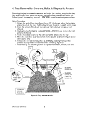
... for easy tray removal. Quick Procedure: 1. Unplug the two front panel cables (CN2008 & CN2009) and remove the front panel (not shown). 4. Figure 2 - Tray removal revealed SA-HT730 / SAHT930 8 CN2010 Contacts = rear CN2008 Contacts = left CN2009 Contacts = rear CAUTION - On the main board, remove the cable (CN2010) attached to expose the sensors, motors...
... for easy tray removal. Quick Procedure: 1. Unplug the two front panel cables (CN2008 & CN2009) and remove the front panel (not shown). 4. Figure 2 - Tray removal revealed SA-HT730 / SAHT930 8 CN2010 Contacts = rear CN2008 Contacts = left CN2009 Contacts = rear CAUTION - On the main board, remove the cable (CN2010) attached to expose the sensors, motors...
Technical Guide
Page 9
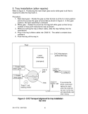
...'s contacts face rearward. 5. 5. Procedure: 1. Rotate the gear so that is clamped. 2. White gear - Without crushing the tray's ribbon cable, slide the tray halfway into CN2010. SA-HT730 / SAHT930 9 Positioning the main black gear and a white gear is all the way in lines point towards the rear as shown in . Plug in the...
...'s contacts face rearward. 5. 5. Procedure: 1. Rotate the gear so that is clamped. 2. White gear - Without crushing the tray's ribbon cable, slide the tray halfway into CN2010. SA-HT730 / SAHT930 9 Positioning the main black gear and a white gear is all the way in lines point towards the rear as shown in . Plug in the...
Technical Guide
Page 10
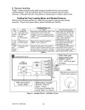
out loading motor 2. S9001 3. Measure the resistance between CN2011 / pin 1 and pin 2. Out) Motor Circuit Cutout shows Q9001 SA-HT730 / SAHT930 10 Sensor testing These 7 electrical parts could cause transport problems but shorted when pressed (simulates tray out). Test all 5 sensors and 2 motors as gear ...
out loading motor 2. S9001 3. Measure the resistance between CN2011 / pin 1 and pin 2. Out) Motor Circuit Cutout shows Q9001 SA-HT730 / SAHT930 10 Sensor testing These 7 electrical parts could cause transport problems but shorted when pressed (simulates tray out). Test all 5 sensors and 2 motors as gear ...

Technical Guide
Page 11
... S9102 6. Press the power on button. Rotate the tray motor gear by hand. Table 5 Proof the part is good Power to begin the remaining tests. 2. SA-HT730 / SAHT930 11 Plug the tray ribbon cable into CN2010 for disc playback. 5Vdc. = Tray in transit. At CN2010/pin 4: Voltage changes from 0.1Vdc to 4.6Vdc...
... S9102 6. Press the power on button. Rotate the tray motor gear by hand. Table 5 Proof the part is good Power to begin the remaining tests. 2. SA-HT730 / SAHT930 11 Plug the tray ribbon cable into CN2010 for disc playback. 5Vdc. = Tray in transit. At CN2010/pin 4: Voltage changes from 0.1Vdc to 4.6Vdc...
Technical Guide
Page 12
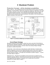
...cable (not shown). Start the repair with speakers). Control unit repair starts on page 17. II Shutdown Problem Protection Concept - The SA-HT930 / SA-HT730 control piece (figure 6, right) has no AC input. The subwoofer (left) houses the power output amplifier for diagnosis is added... (service position). All parts are both 2-piece units (with either the control unit (SA-HT730/HT930) or the subwoofer (SB-WA730/WA930). all 6 channels and delivers protection information to figure 6. Control Unit - Access to ...
...cable (not shown). Start the repair with speakers). Control unit repair starts on page 17. II Shutdown Problem Protection Concept - The SA-HT930 / SA-HT730 control piece (figure 6, right) has no AC input. The subwoofer (left) houses the power output amplifier for diagnosis is added... (service position). All parts are both 2-piece units (with either the control unit (SA-HT730/HT930) or the subwoofer (SB-WA730/WA930). all 6 channels and delivers protection information to figure 6. Control Unit - Access to ...
Technical Guide
Page 13
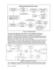
Repair Information Control Unit Repair (SA-HT730 / SA-HT930) Strategy SC-HT730 / SC-HT930 Repair Strategy for both models. Shutdown can be either in the subwoofer. Cutting specific jumpers on the board to stop the shutdown problem ... identical for a shutdown (F61) symptom: These two units differ in power output so the 'HT930 has an additional board in the control unit or subwoofer. SA-HT730 / SAHT930 13 In the control unit, diagnostic troubleshooting is quickly done from the top of the control unit is in the subwoofer or the control...
Repair Information Control Unit Repair (SA-HT730 / SA-HT930) Strategy SC-HT730 / SC-HT930 Repair Strategy for both models. Shutdown can be either in the subwoofer. Cutting specific jumpers on the board to stop the shutdown problem ... identical for a shutdown (F61) symptom: These two units differ in power output so the 'HT930 has an additional board in the control unit or subwoofer. SA-HT730 / SAHT930 13 In the control unit, diagnostic troubleshooting is quickly done from the top of the control unit is in the subwoofer or the control...
Technical Guide
Page 14
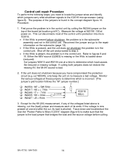
... the 9Vdc is present before cutting. Procedure: 1. If cutting both jumpers does not restore the missing 9V, the M+9V source is missing, cut , its ends. SA-HT730 / SAHT930 14 Control unit repair Procedure To perform the following steps, you have compromised the protection circuit (e.g. Refer to step 2. • If the 9Vdc is...
... the 9Vdc is present before cutting. Procedure: 1. If cutting both jumpers does not restore the missing 9V, the M+9V source is missing, cut , its ends. SA-HT730 / SAHT930 14 Control unit repair Procedure To perform the following steps, you have compromised the protection circuit (e.g. Refer to step 2. • If the 9Vdc is...
Technical Guide
Page 15
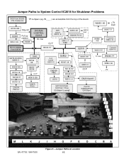
... 7(Tray) IC2008/pin7(Loading) W2235 /K9 Q2801 /C OCP -7V load W2340 /I7 W2854 /H6 -7V CN2010/pin8 PHOTO INTERRUPTER Q9103/pin1 1 2 3 4 5 6 7 8 9 ML K J I HG FE D C BA SA-HT730 / SAHT930 Figure 9 -
... 7(Tray) IC2008/pin7(Loading) W2235 /K9 Q2801 /C OCP -7V load W2340 /I7 W2854 /H6 -7V CN2010/pin8 PHOTO INTERRUPTER Q9103/pin1 1 2 3 4 5 6 7 8 9 ML K J I HG FE D C BA SA-HT730 / SAHT930 Figure 9 -
Technical Guide
Page 16
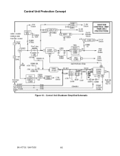
Control Unit Protection Concept Figure 10 - Control Unit Shutdown Simplified Schematic SA-HT730 / SAHT930 16
Control Unit Protection Concept Figure 10 - Control Unit Shutdown Simplified Schematic SA-HT730 / SAHT930 16
Technical Guide
Page 17
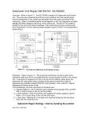
...the 25 pin umbilical cable opens the subwoofer AC relay power relay, shutting off the power for shutdown are connected by isolating the problem SA-HT730 / SAHT930 17 Missing 9V or excessive 9V load that carries power from the Subwoofer to the control unit and audio from the control ...just before power is part of the subwoofer (left) and control unit (right) feed the microprocessor IC2018 in the subwoofer's Power Board. The SC-HT730 model is still present]. The protection monitoring circuitry in both the control & subwoofer [but standby voltage (SYS 6V) is similar but has less ...
...the 25 pin umbilical cable opens the subwoofer AC relay power relay, shutting off the power for shutdown are connected by isolating the problem SA-HT730 / SAHT930 17 Missing 9V or excessive 9V load that carries power from the Subwoofer to the control unit and audio from the control ...just before power is part of the subwoofer (left) and control unit (right) feed the microprocessor IC2018 in the subwoofer's Power Board. The SC-HT730 model is still present]. The protection monitoring circuitry in both the control & subwoofer [but standby voltage (SYS 6V) is similar but has less ...

Technical Guide
Page 18
... board that the subwoofer can be tested alone. 4. See subwoofer repair below. 7. Refer to the Subwoofer. See subwoofer disassembly diagrams figures 13 & 14. 3. E.g. SB-WA730 - SA-HT730 / SAHT930 18 Disassembly and service positions are shorted, momentarily plug the subwoofer into AC. 6. Do not connect the Control unit to figure 12. If the...
... board that the subwoofer can be tested alone. 4. See subwoofer repair below. 7. Refer to the Subwoofer. See subwoofer disassembly diagrams figures 13 & 14. 3. E.g. SB-WA730 - SA-HT730 / SAHT930 18 Disassembly and service positions are shorted, momentarily plug the subwoofer into AC. 6. Do not connect the Control unit to figure 12. If the...
Technical Guide
Page 21
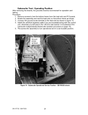
... PC boards. 2. The subwoofer assembly is now operational and in figure 14. 4. Ground screw terminal Front Bd. SBWA930 only Figure 14 - Procedure: 1. SB-WA930 shown SA-HT730 / SAHT930 21 Subwoofer Operational Service Position - Rotate the assembly and rest the heat sink on page 15). 5. Subwoofer Test / Operating Position After removing the boards...
... PC boards. 2. The subwoofer assembly is now operational and in figure 14. 4. Ground screw terminal Front Bd. SBWA930 only Figure 14 - Procedure: 1. SB-WA930 shown SA-HT730 / SAHT930 21 Subwoofer Operational Service Position - Rotate the assembly and rest the heat sink on page 15). 5. Subwoofer Test / Operating Position After removing the boards...
Technical Guide
Page 22
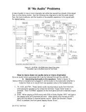
... stereo-only movies (no SFC light) will work. TV, VCR, and FM - When playing a DVD movie with DTS or Dolby Digital ("SFC" will light in the display and) all 6-channels will only deliver 2-channel stereo sound. A- SA-HT730 / SAHT930 22 Use the following two diagrams to the headphones). 1. Notice: When a headphone is plugged...
... stereo-only movies (no SFC light) will work. TV, VCR, and FM - When playing a DVD movie with DTS or Dolby Digital ("SFC" will light in the display and) all 6-channels will only deliver 2-channel stereo sound. A- SA-HT730 / SAHT930 22 Use the following two diagrams to the headphones). 1. Notice: When a headphone is plugged...


