
Technical Guide
Page 7
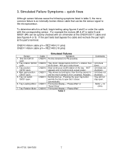
...Disc Det Q9103 open . 6. Tray out switch S9001 open 2. Unit does not shutdown. "INIT" appears and no PB possible). Motor = 14 ohms SA-HT730 / SAHT930 7 Tray moves out and spins, then the tray moves in table 3, the more common failure is at fault, begin testing using figures 4 ...and 5 or order the cable with an ohmmeter at the part's terminal. Tray will not stay open. Front panel display = "Please Wait" or "Open/Close" Front panel display = "Please Wait" Table 3 Comments Unit shuts down . CN2010 ribbon cable p/n = REZ1484 (11 pins) CN2011 ribbon cable p/n...
...Disc Det Q9103 open . 6. Tray out switch S9001 open 2. Unit does not shutdown. "INIT" appears and no PB possible). Motor = 14 ohms SA-HT730 / SAHT930 7 Tray moves out and spins, then the tray moves in table 3, the more common failure is at fault, begin testing using figures 4 ...and 5 or order the cable with an ohmmeter at the part's terminal. Tray will not stay open. Front panel display = "Please Wait" or "Open/Close" Front panel display = "Please Wait" Table 3 Comments Unit shuts down . CN2010 ribbon cable p/n = REZ1484 (11 pins) CN2011 ribbon cable p/n...
Technical Guide
Page 8
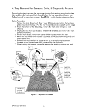
.... On the main board, remove the cable (CN2010) attached to unlock the tray. Slide the tray out towards yourself) until it stops. 2. Tray removal revealed SA-HT730 / SAHT930 8 CN2010 Contacts = rear CN2008 Contacts = left CN2009 Contacts = rear Release the two parallel tray stops (a and b) by pressing the larger tab (... Quick Procedure: 1. Pull the tray forward (towards yourself to access the sensors and motor first requires removing the tray trim, and then the front panel (not shown) before the tray assembly will come out. Tray Removal for easy tray removal. Unplug the two front...
.... On the main board, remove the cable (CN2010) attached to unlock the tray. Slide the tray out towards yourself) until it stops. 2. Tray removal revealed SA-HT730 / SAHT930 8 CN2010 Contacts = rear CN2008 Contacts = left CN2009 Contacts = rear Release the two parallel tray stops (a and b) by pressing the larger tab (... Quick Procedure: 1. Pull the tray forward (towards yourself to access the sensors and motor first requires removing the tray trim, and then the front panel (not shown) before the tray assembly will come out. Tray Removal for easy tray removal. Unplug the two front...
Technical Guide
Page 10
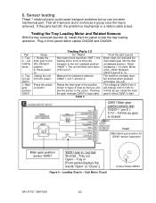
... the transport to test the tray loading operation. Between CN2011/pins 8 & 10. The switch is removed. Tray out Open - Tray in - Tray in [Front panel displays the words "Open" or "Close".] Figure 4 - Press power on. Press the poweron button. Motor resistance = 14 ohms. Motor volts = 8Vdc. Test...tray in front panel ribbon cables CN2008 and CN2009. Unplug the unit from 0.1Vdc to the disc clamped position. 2. Table 4 Proof the part is good Motor must turn belt and the main black gear into the disc unclamped position. Out) Motor Circuit Cutout shows Q9001 SA-HT730 / SAHT930 10...
... the transport to test the tray loading operation. Between CN2011/pins 8 & 10. The switch is removed. Tray out Open - Tray in - Tray in [Front panel displays the words "Open" or "Close".] Figure 4 - Press power on. Press the poweron button. Motor resistance = 14 ohms. Motor volts = 8Vdc. Test...tray in front panel ribbon cables CN2008 and CN2009. Unplug the unit from 0.1Vdc to the disc clamped position. 2. Table 4 Proof the part is good Motor must turn belt and the main black gear into the disc unclamped position. Out) Motor Circuit Cutout shows Q9001 SA-HT730 / SAHT930 10...

Technical Guide
Page 11
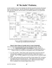
...- 5.6Vdc. Tray Rotation circuit CN2010/Pin 2: 0.15 = disc centered 5Vdc = tray bet discs. With the tray removed, install the front panel to 4.6Vdc Figure 5 - Disc presence detector Q9103 Setup Press the power on top of the unit between the laser block and front...panel. 3. Place the plastic tray on button. Pin 10 = 0V, 2V, 5.6V 3.6Vdc CN2010/Pin 6: 5.0V = Disc 0.3V = No Disc Pin 4: motor rot. 0.1V to begin the remaining tests. 2. Tray M rotation sensor S9102 6. Move the tray past the disc center position at CN2010/pin 2: 0.15Vdc = Tray centered for testing. SA-HT730...
...- 5.6Vdc. Tray Rotation circuit CN2010/Pin 2: 0.15 = disc centered 5Vdc = tray bet discs. With the tray removed, install the front panel to 4.6Vdc Figure 5 - Disc presence detector Q9103 Setup Press the power on top of the unit between the laser block and front...panel. 3. Place the plastic tray on button. Pin 10 = 0V, 2V, 5.6V 3.6Vdc CN2010/Pin 6: 5.0V = Disc 0.3V = No Disc Pin 4: motor rot. 0.1V to begin the remaining tests. 2. Tray M rotation sensor S9102 6. Move the tray past the disc center position at CN2010/pin 2: 0.15Vdc = Tray centered for testing. SA-HT730...
Technical Guide
Page 22
...movies (no SFC light) will work. SA-HT730 / SAHT930 22 How to trace down no sound from the front and subwoofer speakers only unless the remote's "Super Srnd" button is pressed, the front panel display shows "Error". A- Then "S.SRND" appears on the front panel and all the audio to the headphones...Digital ("SFC" will light in the display and) all 6-channels will only deliver 2-channel stereo sound. Use the following two diagrams to figure 15. DVD - When the remote's "Super Srnd" is pressed. III "No Audio" Problems A loss of accessible capacitors in the signal path for signal tracing...
...movies (no SFC light) will work. SA-HT730 / SAHT930 22 How to trace down no sound from the front and subwoofer speakers only unless the remote's "Super Srnd" button is pressed, the front panel display shows "Error". A- Then "S.SRND" appears on the front panel and all the audio to the headphones...Digital ("SFC" will light in the display and) all 6-channels will only deliver 2-channel stereo sound. Use the following two diagrams to figure 15. DVD - When the remote's "Super Srnd" is pressed. III "No Audio" Problems A loss of accessible capacitors in the signal path for signal tracing...
Technical Guide
Page 23
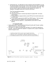
... to select DVD / CD (front panel display). b) Press the front panel or remote input selector to locate the capacitors in this test mode, IC2011 generates a fixed level signal to each speaker, one at each speaker and repeats. Test Tone generating procedure: a) Turn the unit on. e) Stop the test tone sequence - Figure 16 SA-HT730 / SAHT930...
... to select DVD / CD (front panel display). b) Press the front panel or remote input selector to locate the capacitors in this test mode, IC2011 generates a fixed level signal to each speaker, one at each speaker and repeats. Test Tone generating procedure: a) Turn the unit on. e) Stop the test tone sequence - Figure 16 SA-HT730 / SAHT930...


