

PT52LCX16 User Guide
Page 68
... ] (10 % THD) HID Lamp 100 W HID (High Intensity Discharge) Lamp Channel Capability (Digital/Analog) VHF/... Jack × 2) HDMI*1 HDMI 1-2*2 HDMI type A Connector AUDIO L-R 0.5 Vrms (RCA Pin Jack Type × ...PT-52LCX66/PT-56LCX66/PT-61LCX66 *2 For models PT-52LCX16/PT-56LCX16/PT-61LCX16 Note: • Design and Specifications are subject to change without notice. Specifications Power Source Power Consumption LCD panels Display PT-52LCX66/PT-52LCX16 PT-56LCX66/PT-56LCX16 PT-61LCX66/PT-61LCX16 AC 120 V, 60 Hz Power ON: Power OFF: Approx. 190 W (When audio is at : http://www.panasonic...
... ] (10 % THD) HID Lamp 100 W HID (High Intensity Discharge) Lamp Channel Capability (Digital/Analog) VHF/... Jack × 2) HDMI*1 HDMI 1-2*2 HDMI type A Connector AUDIO L-R 0.5 Vrms (RCA Pin Jack Type × ...PT-52LCX66/PT-56LCX66/PT-61LCX66 *2 For models PT-52LCX16/PT-56LCX16/PT-61LCX16 Note: • Design and Specifications are subject to change without notice. Specifications Power Source Power Consumption LCD panels Display PT-52LCX66/PT-52LCX16 PT-56LCX66/PT-56LCX16 PT-61LCX66/PT-61LCX16 AC 120 V, 60 Hz Power ON: Power OFF: Approx. 190 W (When audio is at : http://www.panasonic...

Service Manual
Page 3
...lamp involves a risk of UV-Radiation. Figure 2 1.3. And connect "B" to the chassis, the reading must not exceed 1/2 mA. 1 Safety Precautions PT-52LCX66 / PT-56LCX66 / PT-61LCX66 / PT-52LCX16 / PT...-56LCX16 1.1. Disconnect AC Plug before it has completely cooled off when replacing the Lamp... across the resistor. 4. The lamp emits small amounts of explosion. ...or damaged by covering the Lamp and wearing the UV protective... measurements. 6. Since the lamp reaches a very high temperature... when replacing the lamp. 2. It is...
...lamp involves a risk of UV-Radiation. Figure 2 1.3. And connect "B" to the chassis, the reading must not exceed 1/2 mA. 1 Safety Precautions PT-52LCX66 / PT-56LCX66 / PT-61LCX66 / PT-52LCX16 / PT...-56LCX16 1.1. Disconnect AC Plug before it has completely cooled off when replacing the Lamp... across the resistor. 4. The lamp emits small amounts of explosion. ...or damaged by covering the Lamp and wearing the UV protective... measurements. 6. Since the lamp reaches a very high temperature... when replacing the lamp. 2. It is...

Service Manual
Page 19
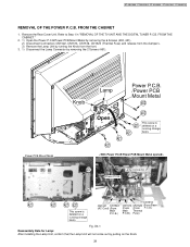
Clamper P2821 (Thermistor 2 P.C.B.) Thermal Fuse Speaker Connector Power Switch P.C.B. Hook Lamp Connector Clamper Clamper CN6801 (From Main P.C.B.) Fan3 Fig. 9-4 19 It is important for the following. Note: Use extreme care especially for the best operation of the unit. PT-52LCX66 / PT-56LCX66 / PT-61LCX66 / PT-52LCX16 / PT-56LCX16 After servicing, make sure that all wires, leads, and clampers are placed in their original position.
Clamper P2821 (Thermistor 2 P.C.B.) Thermal Fuse Speaker Connector Power Switch P.C.B. Hook Lamp Connector Clamper Clamper CN6801 (From Main P.C.B.) Fan3 Fig. 9-4 19 It is important for the following. Note: Use extreme care especially for the best operation of the unit. PT-52LCX66 / PT-56LCX66 / PT-61LCX66 / PT-52LCX16 / PT-56LCX16 After servicing, make sure that all wires, leads, and clampers are placed in their original position.
Service Manual
Page 27
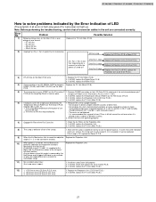
... 12) 1. +17V line on the LCD Drive P.C.B. PT-52LCX66 / PT-56LCX66 / PT-61LCX66 / PT-52LCX16 / PT-56LCX16 How to solve problems indicated by the Hall Sensor. All Fans stop. error. 1. Remove CN2301 connector on the LCD Drive P.C.B. Wait until the Lamp is defective (short of use may be replaced. If the... Lamp is supplied to the Motor and the...
... 12) 1. +17V line on the LCD Drive P.C.B. PT-52LCX66 / PT-56LCX66 / PT-61LCX66 / PT-52LCX16 / PT-56LCX16 How to solve problems indicated by the Hall Sensor. All Fans stop. error. 1. Remove CN2301 connector on the LCD Drive P.C.B. Wait until the Lamp is defective (short of use may be replaced. If the... Lamp is supplied to the Motor and the...

Service Manual
Page 28
PT-52LCX66 / PT-56LCX66 / PT-61LCX66 / PT-52LCX16 / PT-56LCX16 LAMP DOES NOT LIGHT UP Plug in the unit are connected to the connectors correctly. 2. When doing this troubleshooting, confirm that all connector cables in the AC Cord. The Power LED (D6801) goes off and unplug the AC Cord. 3. Perform troubleshooting. If still NG, replace the TV Unit (...
PT-52LCX66 / PT-56LCX66 / PT-61LCX66 / PT-52LCX16 / PT-56LCX16 LAMP DOES NOT LIGHT UP Plug in the unit are connected to the connectors correctly. 2. When doing this troubleshooting, confirm that all connector cables in the AC Cord. The Power LED (D6801) goes off and unplug the AC Cord. 3. Perform troubleshooting. If still NG, replace the TV Unit (...
Service Manual
Page 39
... the Lamp Unit by turning the Knob from the front. 3. 1) Disconnect the Lamp Connector by pulling on a P.C.B.) P.C.B.) Fuse) running change basis. Fig. D4-1 Reassembly Note for Lamp: After installing the Lamp Unit, confirm that the Lamp Unit ...Lamp Connector Power P.C.B. 451 451 402 421 421 421 421 CN1516 CN1001 CN1522 (AC Cord) (From CN1514 CN1520 (From Base (From (From P.C.B.) This screw is Main Main Thermal deleted on the Knob. 39 Remove the Rear Cover Unit. Refer to Step 1 in "REMOVAL OF THE TV UNIT AND THE DIGITAL TUNER P.C.B. PT-52LCX66 / PT-56LCX66 / PT...
... the Lamp Unit by turning the Knob from the front. 3. 1) Disconnect the Lamp Connector by pulling on a P.C.B.) P.C.B.) Fuse) running change basis. Fig. D4-1 Reassembly Note for Lamp: After installing the Lamp Unit, confirm that the Lamp Unit ...Lamp Connector Power P.C.B. 451 451 402 421 421 421 421 CN1516 CN1001 CN1522 (AC Cord) (From CN1514 CN1520 (From Base (From (From P.C.B.) This screw is Main Main Thermal deleted on the Knob. 39 Remove the Rear Cover Unit. Refer to Step 1 in "REMOVAL OF THE TV UNIT AND THE DIGITAL TUNER P.C.B. PT-52LCX66 / PT-56LCX66 / PT...
Service Manual
Page 80
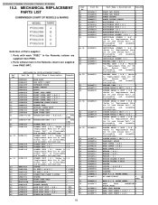
...UNIT ( A,D ) 1 FRONT COVER UNIT ( B,E ) 1 FRONT COVER UNIT ( C ) 1 CONNECTOR CABLE W/PLUG 2 RUBBER FOOT 2 OPTICAL COVER UNIT 2 LAMP COVER UNIT 2 REAR COVER UNIT 1 PROJECTION UNIT ( A,B,D,E ) 5 RTL PSEC PROJECTION UNIT ( ...LENTICULAR SCREEN ( B,E ) 4 *Refer to "Replacement Note for 56 inch Screen Unit" in Disassembly and Assembly Instructions. SCREEN ANGLE V UNIT ( C ) 4 PANASONIC BADGE 1 BACK COVER ( A,D ) 3 BACK COVER ( B,E ) 3 BACK COVER ( C ) 3 MIRROR ( A,D ) 3 MIRROR ( B,E ) 3... PT-52LCX66 / PT-56LCX66 / PT-61LCX66 / PT-52LCX16 / PT-56LCX16 15.2.
...UNIT ( A,D ) 1 FRONT COVER UNIT ( B,E ) 1 FRONT COVER UNIT ( C ) 1 CONNECTOR CABLE W/PLUG 2 RUBBER FOOT 2 OPTICAL COVER UNIT 2 LAMP COVER UNIT 2 REAR COVER UNIT 1 PROJECTION UNIT ( A,B,D,E ) 5 RTL PSEC PROJECTION UNIT ( ...LENTICULAR SCREEN ( B,E ) 4 *Refer to "Replacement Note for 56 inch Screen Unit" in Disassembly and Assembly Instructions. SCREEN ANGLE V UNIT ( C ) 4 PANASONIC BADGE 1 BACK COVER ( A,D ) 3 BACK COVER ( B,E ) 3 BACK COVER ( C ) 3 MIRROR ( A,D ) 3 MIRROR ( B,E ) 3... PT-52LCX66 / PT-56LCX66 / PT-61LCX66 / PT-52LCX16 / PT-56LCX16 15.2.

Service Manual
Page 81
... purchase a replacement, call the Panasonic accessory department. 15.4. Parts with...RTL PSEC 5 5 15.3. LAMP UNIT Ref. TY-LA1001 Part Name & Description LAMP UNIT Remarks 5 NOTE NOTE: The Lamp Unit (TY-LA1001) is ...TAPPING SCREW,STEEL 2,3,4 SCREW W/WASHER,STEEL 2 SCREW W/WASHER,STEEL 5,6 TAPPING SCREW,STEEL 1 CLAMPER 5 PSEC FERRITE CORE 6 CONNECTOR CABLE W/PLUG 5 PSEC MAIN P.C.B. ( A,B,C ) 6 RTL MAIN P.C.B. ( D,E ) 6 RTL BASE P.C.B. ( A,B,C )...E60 E100 E130 E140 E150 24 492 PT-52LCX66 / PT-56LCX66 / PT-61LCX66 / PT-52LCX16 / PT-56LCX16 Part No. Ref. RTL PSEC...
... purchase a replacement, call the Panasonic accessory department. 15.4. Parts with...RTL PSEC 5 5 15.3. LAMP UNIT Ref. TY-LA1001 Part Name & Description LAMP UNIT Remarks 5 NOTE NOTE: The Lamp Unit (TY-LA1001) is ...TAPPING SCREW,STEEL 2,3,4 SCREW W/WASHER,STEEL 2 SCREW W/WASHER,STEEL 5,6 TAPPING SCREW,STEEL 1 CLAMPER 5 PSEC FERRITE CORE 6 CONNECTOR CABLE W/PLUG 5 PSEC MAIN P.C.B. ( A,B,C ) 6 RTL MAIN P.C.B. ( D,E ) 6 RTL BASE P.C.B. ( A,B,C )...E60 E100 E130 E140 E150 24 492 PT-52LCX66 / PT-56LCX66 / PT-61LCX66 / PT-52LCX16 / PT-56LCX16 Part No. Ref. RTL PSEC...


