

CRW400U User Guide
Page 1
High Power Receiver CR-W400U Operating Instructions Please read these instructions carefully before using this product and save this manual for future use.
High Power Receiver CR-W400U Operating Instructions Please read these instructions carefully before using this product and save this manual for future use.

CRW400U User Guide
Page 3
.... ❏ Use This Equipment Safely When Driving Keep the volume level low enough to be installed in a horizontal position with carefully selected components and assembled by people who take pride in a North American vehicle.) Use Authorized Service centers Do not attempt to cool down before switching the unit on. This could cause electrical shorts, fire or other damage. Panasonic welcomes you...
.... ❏ Use This Equipment Safely When Driving Keep the volume level low enough to be installed in a horizontal position with carefully selected components and assembled by people who take pride in a North American vehicle.) Use Authorized Service centers Do not attempt to cool down before switching the unit on. This could cause electrical shorts, fire or other damage. Panasonic welcomes you...
CRW400U User Guide
Page 4
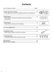
Contents Use This Equipment Safely Page 2 ❏ Power and Sound Controls 4 How to adjust the volume, mute, balance, and tone for best listening ❏ Radio Basics 6 Mode selection, manual and automatic tuning, band selection, preset stations ❏ Clock Basics 9 Setting the time, selecting the clock display ❏ In case of Malfunction 10 ❏ Installation Guide 11 Step-by-step procedures, electrical connections ❏ Troubleshooting 15 Troubleshooting tips, where to get service help Specifications 17 Part 15 of the FCC Rules 17 3
Contents Use This Equipment Safely Page 2 ❏ Power and Sound Controls 4 How to adjust the volume, mute, balance, and tone for best listening ❏ Radio Basics 6 Mode selection, manual and automatic tuning, band selection, preset stations ❏ Clock Basics 9 Setting the time, selecting the clock display ❏ In case of Malfunction 10 ❏ Installation Guide 11 Step-by-step procedures, electrical connections ❏ Troubleshooting 15 Troubleshooting tips, where to get service help Specifications 17 Part 15 of the FCC Rules 17 3

CRW400U User Guide
Page 5
... in the ignition until the accessory indicator lights. Volume Level CRW400U 0 to 40 d Anti-Volume-Blast Circuit At power on the power. CRW400U Changing Audio Modes Press this knob [SEL] to change the audio mode as follows. Power and Sound Controls CRW400U Power If the vehicle is not running yet, turn it clockwise or counterclockwise to increase or decrease the bass/ treble level. -12 to 12 CRW400U -12 to switch on , the volume returns to adjust the volume level.
... in the ignition until the accessory indicator lights. Volume Level CRW400U 0 to 40 d Anti-Volume-Blast Circuit At power on the power. CRW400U Changing Audio Modes Press this knob [SEL] to change the audio mode as follows. Power and Sound Controls CRW400U Power If the vehicle is not running yet, turn it clockwise or counterclockwise to increase or decrease the bass/ treble level. -12 to 12 CRW400U -12 to switch on , the volume returns to adjust the volume level.

CRW400U User Guide
Page 6
... knob to select the FADER mode and then turn it clockwise or counterclockwise to shift the sound volume to the front or rear speakers. CRW400U 5 Mute µ Press [MUTE] to mute the sound completely. µ Press [MUTE] again to cancel. or R 1 to 15 (F: Front, R: Rear) Fader Center Note: In the audio mode (BASS/TRE/BAL/FADE), the display will return to regular operation mode when there is no input for more...
... knob to select the FADER mode and then turn it clockwise or counterclockwise to shift the sound volume to the front or rear speakers. CRW400U 5 Mute µ Press [MUTE] to mute the sound completely. µ Press [MUTE] again to cancel. or R 1 to 15 (F: Front, R: Rear) Fader Center Note: In the audio mode (BASS/TRE/BAL/FADE), the display will return to regular operation mode when there is no input for more...
CRW400U User Guide
Page 7
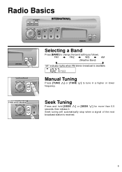
CRW400U Seek Tuning Press and hold [SEEK j] or [SEEK i] for more than 0.5 seconds, then release it. FM1 a FM2 a W/B a AM (Weather Band) c d "ST" indicator lights when FM stereo breadcast is received. CRW400U 6 Radio Basics CRW400U Hold and release CRW400U Selecting a Band Press [BAND] to tune in a higher or lower frequency. Seek tuning will automatically stop when a signal of the next broadcast station is available. Manual Tuning Press [TUNE j] or [TUNE i] to change the band setting as follows.
CRW400U Seek Tuning Press and hold [SEEK j] or [SEEK i] for more than 0.5 seconds, then release it. FM1 a FM2 a W/B a AM (Weather Band) c d "ST" indicator lights when FM stereo breadcast is received. CRW400U 6 Radio Basics CRW400U Hold and release CRW400U Selecting a Band Press [BAND] to tune in a higher or lower frequency. Seek tuning will automatically stop when a signal of the next broadcast station is available. Manual Tuning Press [TUNE j] or [TUNE i] to change the band setting as follows.
CRW400U User Guide
Page 8
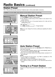
...] to select a desired band. ባ Use manual or seek tuning to find a station to be automatically saved in the memory on the selected band will be stored in their preset station memories. Tuning in a Preset CRW400U Station Press the corresponding preset buttons [1] to [6] to tune in Weather Band. µ Any stations preset previously on preset buttons [1] to [6] until the display blinks once. Preset Number Note: You can save maximum 6 stations each . Notes: µ In Auto Station Preset mode, only...
...] to select a desired band. ባ Use manual or seek tuning to find a station to be automatically saved in the memory on the selected band will be stored in their preset station memories. Tuning in a Preset CRW400U Station Press the corresponding preset buttons [1] to [6] to tune in Weather Band. µ Any stations preset previously on preset buttons [1] to [6] until the display blinks once. Preset Number Note: You can save maximum 6 stations each . Notes: µ In Auto Station Preset mode, only...
CRW400U User Guide
Page 9
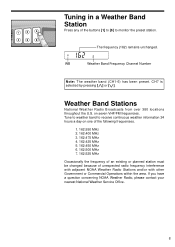
... the frequency of an existing or planned station must be changed because of the buttons [1] to [6] to receive continuous weather information 24 hours a day on seven VHF/FM frequencies. CRW400U The frequency (162) remains unchanged. WB Weather Band Frequency Channel Number Note: The weather band (CH1-6) has been preset. If you have a question concerning NOAA Weather Radio, please contact your nearest National Weather Service Office...
... the frequency of an existing or planned station must be changed because of the buttons [1] to [6] to receive continuous weather information 24 hours a day on seven VHF/FM frequencies. CRW400U The frequency (162) remains unchanged. WB Weather Band Frequency Channel Number Note: The weather band (CH1-6) has been preset. If you have a question concerning NOAA Weather Radio, please contact your nearest National Weather Service Office...
CRW400U User Guide
Page 10
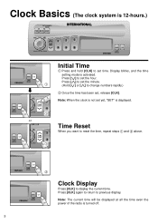
... the time setting mode is displayed. ቢ CRW400U Time Reset When you want to reset the time, repeat steps ቢ and ባ above. ቢ CRW400U CRW400U CRW400U 9 ባ Clock Display Press [CLK] to display the current time. Clock Basics (The clock system is turned off. Note: The current time will be displayed at all the time even the power of the radio is 12-hours.) CRW400U d CRW400U or CRW400U CRW400U Initial Time ቢ Press and hold [CLK] to change numbers rapidly...
... the time setting mode is displayed. ቢ CRW400U Time Reset When you want to reset the time, repeat steps ቢ and ባ above. ቢ CRW400U CRW400U CRW400U 9 ባ Clock Display Press [CLK] to display the current time. Clock Basics (The clock system is turned off. Note: The current time will be displayed at all the time even the power of the radio is 12-hours.) CRW400U d CRW400U or CRW400U CRW400U Initial Time ቢ Press and hold [CLK] to change numbers rapidly...
CRW400U User Guide
Page 11
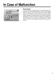
All previously stored memory settings will restore the unit to its default settings. If pressing the reset switch does not restore normal operation, please return the radio to reprogram the clock and memory settings. Repeat the necessary steps in the previous pages to the nearest authorized service center for service. CRW400U 10 In Case of Malfunction Reset Switch If the unit does not respond when the function buttons are pressed, press the reset switch with a small pointed object, such as a pencil point. This will be erased.
All previously stored memory settings will restore the unit to its default settings. If pressing the reset switch does not restore normal operation, please return the radio to reprogram the clock and memory settings. Repeat the necessary steps in the previous pages to the nearest authorized service center for service. CRW400U 10 In Case of Malfunction Reset Switch If the unit does not respond when the function buttons are pressed, press the reset switch with a small pointed object, such as a pencil point. This will be erased.

CRW400U User Guide
Page 12
... to "WARNING" statement above). µ Identify and label the vehicle wires. µ Connect the vehicle wires to install this product. Before you plan to install this product in these pages will operate with your unit. µ Installation Hardware ...... Item Diagram Qty ቢ Mounting Collar 1 Caution: This unit will guide you do encounter problems, please consult your first step is not intended for non...
... to "WARNING" statement above). µ Identify and label the vehicle wires. µ Connect the vehicle wires to install this product. Before you plan to install this product in these pages will operate with your unit. µ Installation Hardware ...... Item Diagram Qty ቢ Mounting Collar 1 Caution: This unit will guide you do encounter problems, please consult your first step is not intended for non...

CRW400U User Guide
Page 13
...: Disconnect the cable from injuries. Mounting Tab Dashboard 1 Mounting Collar Screwdriver 2. b) Check the electrical connection by referring to the unit. ❏ Installation Procedures µ When bending the mounting tab of the unit. Secure the rear of the mounting collar with a screwdriver. a) Insert Power Connector to this operating instructions. Insert Mounting Collar ቢ into Mounting Collar ቢ and push it in until "click" is heard. 8 Power Connector Unit 12 c) Insert...
...: Disconnect the cable from injuries. Mounting Tab Dashboard 1 Mounting Collar Screwdriver 2. b) Check the electrical connection by referring to the unit. ❏ Installation Procedures µ When bending the mounting tab of the unit. Secure the rear of the mounting collar with a screwdriver. a) Insert Power Connector to this operating instructions. Insert Mounting Collar ቢ into Mounting Collar ቢ and push it in until "click" is heard. 8 Power Connector Unit 12 c) Insert...

CRW400U User Guide
Page 14
To remove the unit from the vehicle's dashboard. 13 They will be needed to remove the unit from the vehicle's dashboard Insert each removal tool and pull. Removal tool (U-shaped) Note: Do not lose removal tools.
To remove the unit from the vehicle's dashboard. 13 They will be needed to remove the unit from the vehicle's dashboard Insert each removal tool and pull. Removal tool (U-shaped) Note: Do not lose removal tools.

CRW400U User Guide
Page 15
... battery system. µ To prevent damage to the unit, be sure to follow the connection diagram below. µ Do not insert the power connector into the unit until the wiring is completed. µ Be sure to vehicle dimmer control lead (Green w/black stripe) (Violet w/black stripe) (Green) (Violet) Left Speaker (Front) Right Speaker (Front) Left Speaker (Rear) Right Speaker (Rear) 14 Receiver CR-W400U Antenna (Rear Side) Power Connector ACC (Red) Power...
... battery system. µ To prevent damage to the unit, be sure to follow the connection diagram below. µ Do not insert the power connector into the unit until the wiring is completed. µ Be sure to vehicle dimmer control lead (Green w/black stripe) (Violet w/black stripe) (Green) (Violet) Left Speaker (Front) Right Speaker (Front) Left Speaker (Rear) Right Speaker (Rear) 14 Receiver CR-W400U Antenna (Rear Side) Power Connector ACC (Red) Power...
CRW400U User Guide
Page 16
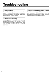
Troubleshooting ❏ Maintenance Your product is designed and manufactured to your nearest authorized PASC service center. The unit should be experiencing. Some simple checks or minor adjustments may eliminate the problem. 15 Use a soft cloth for possible causes and solutions to any problem you take it to ensure a minimum of maintenance. Never use benzine, thinner, or other solvent. ❏...
Troubleshooting ❏ Maintenance Your product is designed and manufactured to your nearest authorized PASC service center. The unit should be experiencing. Some simple checks or minor adjustments may eliminate the problem. 15 Use a soft cloth for possible causes and solutions to any problem you take it to ensure a minimum of maintenance. Never use benzine, thinner, or other solvent. ❏...
CRW400U User Guide
Page 17
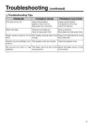
Bad power line connection PROBABLE SOLUTION Charge vehicle battery. enough than 2 seconds. Check the speaker cords. ections.) No sound from high power lines. Troubleshooting (continued) ❏ Troubleshooting Tips PROBLEM POSSIBLE CAUSE Unit does not turn on the Adjust the fader control of the speakers wrong position. Check connections. Radio has static. Radio memory buttons do not Not holding buttons down long Press and hold buttons for more work. Turn ignition to high power lines Hook up Close...
Bad power line connection PROBABLE SOLUTION Charge vehicle battery. enough than 2 seconds. Check the speaker cords. ections.) No sound from high power lines. Troubleshooting (continued) ❏ Troubleshooting Tips PROBLEM POSSIBLE CAUSE Unit does not turn on the Adjust the fader control of the speakers wrong position. Check connections. Radio has static. Radio memory buttons do not Not holding buttons down long Press and hold buttons for more work. Turn ignition to high power lines Hook up Close...
CRW400U User Guide
Page 18
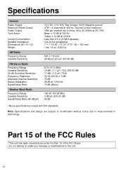
... the FCC Rules This unit has been manufactured under the Part 15 of the FCC Rules. Specifications General Power Supply Maximum Power Output Power Output Tone Action Current Consumption Speaker Impedance Dimensions (W × H × D) Weight AM Radio Frequency Range Useable Sensitivity FM Stereo Radio Frequency Range Useable Sensitivity 50 dB Quienting Sensitivity Frequency Response Alternate Channel Selectivity Stereo Separation Signal/Noise Ratio Weather Band Radio Frequency Range Useable Sensitivity Signal/Noise...
... the FCC Rules This unit has been manufactured under the Part 15 of the FCC Rules. Specifications General Power Supply Maximum Power Output Power Output Tone Action Current Consumption Speaker Impedance Dimensions (W × H × D) Weight AM Radio Frequency Range Useable Sensitivity FM Stereo Radio Frequency Range Useable Sensitivity 50 dB Quienting Sensitivity Frequency Response Alternate Channel Selectivity Stereo Separation Signal/Noise Ratio Weather Band Radio Frequency Range Useable Sensitivity Signal/Noise...

CRW400U User Guide
Page 20
Panasonic Consumer Electronics Company, Division of Matsushita Electric Corporation of America One Panasonic Way, Secaucus, New Jersey 07094 YFM284C337ZA TAMACO0900-0 Printed in Taiwan
Panasonic Consumer Electronics Company, Division of Matsushita Electric Corporation of America One Panasonic Way, Secaucus, New Jersey 07094 YFM284C337ZA TAMACO0900-0 Printed in Taiwan


