Installation Guide
Page 1
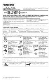
... secure the camera when mounting it can be accessed using a PC. • Refer to the Operating Instructions on the CD-ROM if you know the names of each document. - All Rights Reserved. of your network and to install and setup the camera. Setup Setting up the camera so that it . PQLV202U Cord Length: About 3 m (9 feet 10 inches) Safety Wire (1 pc.) Order No. a router - Connections Connecting the camera to the Troubleshooting Guide...
... secure the camera when mounting it can be accessed using a PC. • Refer to the Operating Instructions on the CD-ROM if you know the names of each document. - All Rights Reserved. of your network and to install and setup the camera. Setup Setting up the camera so that it . PQLV202U Cord Length: About 3 m (9 feet 10 inches) Safety Wire (1 pc.) Order No. a router - Connections Connecting the camera to the Troubleshooting Guide...
Installation Guide
Page 2
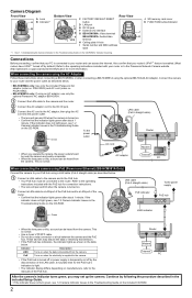
... the power outlet. • The lens will pan and tilt when the camera is turned on manufacturers, refer to the manuals of the PoE hub. PQLV202U) and AC cord (order no . PSJA1069Z). • BB-HCM581A only: If using the optional BB-HCA3A AC Adaptor. Refer to the operating instructions included with your router and can be heard from the camera. Camera Diagram Front View A Lens A B Indicator*1 B Bottom View C D E F I HG Rear View C FACTORY DEFAULT RESET button D LAN port...
... the power outlet. • The lens will pan and tilt when the camera is turned on manufacturers, refer to the manuals of the PoE hub. PQLV202U) and AC cord (order no . PSJA1069Z). • BB-HCM581A only: If using the optional BB-HCA3A AC Adaptor. Refer to the operating instructions included with your router and can be heard from the camera. Camera Diagram Front View A Lens A B Indicator*1 B Bottom View C D E F I HG Rear View C FACTORY DEFAULT RESET button D LAN port...
Installation Guide
Page 3
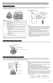
... Section 2 Using Triggers to monitor or record camera images. Connect the devices as shown below . See 7.5 Controlling the Analog Video Output Signal in the Setup Guide. The output signal is mono. • Make sure the camera and speaker are used . Under no longer than 7 m (23 feet). • Use a speaker with a stereo audio cable similar to the procedure described in the Operating Instructions on the CD-ROM for example, turning a light on...
... Section 2 Using Triggers to monitor or record camera images. Connect the devices as shown below . See 7.5 Controlling the Analog Video Output Signal in the Setup Guide. The output signal is mono. • Make sure the camera and speaker are used . Under no longer than 7 m (23 feet). • Use a speaker with a stereo audio cable similar to the procedure described in the Operating Instructions on the CD-ROM for example, turning a light on...
Installation Guide
Page 4
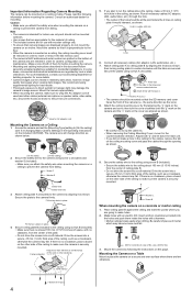
... lighting for residential installations. Mount the camera so that camera images are needed in order for use only and should not be mounted outdoors. • Use screws that are appropriate for the material of the camera (i.e., the same direction as shown. Run all necessary cables (AC adaptor, LAN, audio/video, etc.). 7. Secure the plate to the camera by local or state ordinances. If there is securely mounted. Secure the safety wire...
... lighting for residential installations. Mount the camera so that camera images are needed in order for use only and should not be mounted outdoors. • Use screws that are appropriate for the material of the camera (i.e., the same direction as shown. Run all necessary cables (AC adaptor, LAN, audio/video, etc.). 7. Secure the plate to the camera by local or state ordinances. If there is securely mounted. Secure the safety wire...


