

AJHDR150 User Guide
Page 1
HD/SD Multi Format DVCPRO Server AJ- P Operating Instructions
HD/SD Multi Format DVCPRO Server AJ- P Operating Instructions
AJHDR150 User Guide
Page 3
... limits for a class A digital device, pursuant to Part 15 of the FCC Rules. This equipment generates, uses, and can radiate radio frequency energy and, if not installed and used in order to maintain adequate ventilation. CAUTION: Do not install or place this unit is intended to alert the user to the presence of important operating and maintenance (service) instructions in the literature accompanying...
... limits for a class A digital device, pursuant to Part 15 of the FCC Rules. This equipment generates, uses, and can radiate radio frequency energy and, if not installed and used in order to maintain adequate ventilation. CAUTION: Do not install or place this unit is intended to alert the user to the presence of important operating and maintenance (service) instructions in the literature accompanying...

AJHDR150 User Guide
Page 4
... Channel Setting Screen 21 Parameter Setting Screen 22 Version Display Screen 22 Error Display Screen 24 CLIP Display Screen 25 CLIP Erase Screen 25 CLIP Rename Screen 25 Simplified Manual Operation Screen 26 CLIP Load Screen 28 CLIP Creation Screen 28 HDD Status Display Screen 29 HDD Reconstruction Selection Screen 29 Error Log Display Screen 30 Error Log Detailed Display Screen 30 Optional Board Installation Method. . . . 31 1. SDI I/O board (AJ-YA7100P 35 Optional HDD 36 Troubleshooting 37 Connector Signals 38 Specifications 40 O Windows, Windows 95, Windows...
... Channel Setting Screen 21 Parameter Setting Screen 22 Version Display Screen 22 Error Display Screen 24 CLIP Display Screen 25 CLIP Erase Screen 25 CLIP Rename Screen 25 Simplified Manual Operation Screen 26 CLIP Load Screen 28 CLIP Creation Screen 28 HDD Status Display Screen 29 HDD Reconstruction Selection Screen 29 Error Log Display Screen 30 Error Log Detailed Display Screen 30 Optional Board Installation Method. . . . 31 1. SDI I/O board (AJ-YA7100P 35 Optional HDD 36 Troubleshooting 37 Connector Signals 38 Specifications 40 O Windows, Windows 95, Windows...
AJHDR150 User Guide
Page 5
... in the power supply unit, be sure to always turn the relevant power supply switch to OFF. $ Precautions for input/output from a VTR to the front panel side. Handling Precautions OThis unit has been designed with a new one, but backup copies of HD signal from your dealer but normal operation thereafter cannot be restored. O The system is maintained, but lost due to facilitate data restoration...
... in the power supply unit, be sure to always turn the relevant power supply switch to OFF. $ Precautions for input/output from a VTR to the front panel side. Handling Precautions OThis unit has been designed with a new one, but backup copies of HD signal from your dealer but normal operation thereafter cannot be restored. O The system is maintained, but lost due to facilitate data restoration...

AJHDR150 User Guide
Page 6
.... Features DVCPRO compression This digital video server incorporates the DVCPRO format that, in the development of digital technology for broadcasting applications, has won critical acclaim for a VTR system. High-speed transmission made possible by Fibre Channel connection Expanding input/output channels and strage capacity is obtained. (When 8 units of all DVCPRO format signals (DVCPRO 25M/50M/P/HD) is possible to upload or download image data to construct time-difference systems...
.... Features DVCPRO compression This digital video server incorporates the DVCPRO format that, in the development of digital technology for broadcasting applications, has won critical acclaim for a VTR system. High-speed transmission made possible by Fibre Channel connection Expanding input/output channels and strage capacity is obtained. (When 8 units of all DVCPRO format signals (DVCPRO 25M/50M/P/HD) is possible to upload or download image data to construct time-difference systems...

AJHDR150 User Guide
Page 8
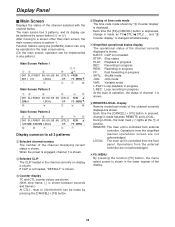
... of a gross error, the lamp lights in HDD has been accessed. Turning the power off when the power switches of the display panel. During ATTN-MODE: The lamp turns orange and blinks whenever something wrong with information on the menu are at OFF. In the event of channel selected with channel select button, along with the output voltage, cooling fan or power supply module temperature. The operations allocated to...
... of a gross error, the lamp lights in HDD has been accessed. Turning the power off when the power switches of the display panel. During ATTN-MODE: The lamp turns orange and blinks whenever something wrong with information on the menu are at OFF. In the event of channel selected with channel select button, along with the output voltage, cooling fan or power supply module temperature. The operations allocated to...
AJHDR150 User Guide
Page 9
.... Channel 1 is controlled from an external controller. Handle Combining the CANCEL button with the external controller. [CANCEL]+[F4] (TC/CTL): Displays the time code mode. Moves the cursor one space to the right. [SET] button: Becomes effective when "SET or CANCEL" is repeated. [CANCEL]+[F3] (REMOTE/LOCAL): Switches the channel currently shown on the display between REMOTE and LOCAL each time [CANCEL] + [F3] is designated can be viewed on the display panel. Operations...
.... Channel 1 is controlled from an external controller. Handle Combining the CANCEL button with the external controller. [CANCEL]+[F4] (TC/CTL): Displays the time code mode. Moves the cursor one space to the right. [SET] button: Becomes effective when "SET or CANCEL" is repeated. [CANCEL]+[F3] (REMOTE/LOCAL): Switches the channel currently shown on the display between REMOTE and LOCAL each time [CANCEL] + [F3] is designated can be viewed on the display panel. Operations...
AJHDR150 User Guide
Page 11
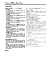
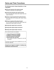
... dealer for any or all of the four channels. Analog out board (AJ-YA7200P) 3. SDTI panel (packed with optional board) Nothing is connected to the SDTI panel. @ Analog panel (packed with optional board) This is provided with analog audio signal input and output connectors. Parts and Their Functions The following panels change depending on setting and installing the optional boards. 11
... dealer for any or all of the four channels. Analog out board (AJ-YA7200P) 3. SDTI panel (packed with optional board) Nothing is connected to the SDTI panel. @ Analog panel (packed with optional board) This is provided with analog audio signal input and output connectors. Parts and Their Functions The following panels change depending on setting and installing the optional boards. 11
AJHDR150 User Guide
Page 16
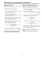
... I/O LOCAL -DF- Connect power cord and signal line. When the power switch is set to shut down the system and turn off the power supply while the unit is shown on the display. Never turn off the power supply during startup. Connect the FC cable between the Fibre Channel connectors [RAID] and [HOST]. 4. Turn the POWER switch on the front panel display. Refer to the display panel menu flowchart to AC power socket for data. (See page...
... I/O LOCAL -DF- Connect power cord and signal line. When the power switch is set to shut down the system and turn off the power supply while the unit is shown on the display. Never turn off the power supply during startup. Connect the FC cable between the Fibre Channel connectors [RAID] and [HOST]. 4. Turn the POWER switch on the front panel display. Refer to the display panel menu flowchart to AC power socket for data. (See page...
AJHDR150 User Guide
Page 18
... between REMOTE and LOCAL. and "3 Counter display" is changed simultaneously. 5 Simplified operational status display The operational status of the channel displaying current status is shown. F5:MENU = > 8 7 9 Display common to pattern 1. Each time the [F4]+[CANCEL] button is depressed, change is not loaded. After moving to a screen other than main screen, the main screen returns to all 3 patterns 1 Selected channel number The number of the channel currently displayed is shown. Function buttons using...
... between REMOTE and LOCAL. and "3 Counter display" is changed simultaneously. 5 Simplified operational status display The operational status of the channel displaying current status is shown. F5:MENU = > 8 7 9 Display common to pattern 1. Each time the [F4]+[CANCEL] button is depressed, change is not loaded. After moving to a screen other than main screen, the main screen returns to all 3 patterns 1 Selected channel number The number of the channel currently displayed is shown. Function buttons using...
AJHDR150 User Guide
Page 19
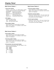
... I/O: SDI input/output board ANALOG I/O: Analog input/output board 7 DF display Displays DF/NDF setting. -DF-: Drop frame mode -NDF-: Non drop frame mode : Next pattern display Shows that there is displayed. ; When cursor button [#] is pressed, main screen pattern 2 is displayed. = Residual capacity display Shows the remaining time to the last minute that recording can be done on the main unit. (Conversion by DVCPRO 25Mbps) > Total capacity display Shows...
... I/O: SDI input/output board ANALOG I/O: Analog input/output board 7 DF display Displays DF/NDF setting. -DF-: Drop frame mode -NDF-: Non drop frame mode : Next pattern display Shows that there is displayed. ; When cursor button [#] is pressed, main screen pattern 2 is displayed. = Residual capacity display Shows the remaining time to the last minute that recording can be done on the main unit. (Conversion by DVCPRO 25Mbps) > Total capacity display Shows...
AJHDR150 User Guide
Page 20
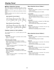
... the channel setting screen for details. When the [F4] button is pressed, the version display screen is displayed. Example: When currently at pattern 1, the change is from pattern 2 to pattern 1. = Next pattern display Shows that there is a screen pattern to 5 are displayed in the lower register of menu. See the final setting screen for details. 7 [F2] MANU When the [F2] button is pressed, the simplified manual operation screen...
... the channel setting screen for details. When the [F4] button is pressed, the version display screen is displayed. Example: When currently at pattern 1, the change is from pattern 2 to pattern 1. = Next pattern display Shows that there is a screen pattern to 5 are displayed in the lower register of menu. See the final setting screen for details. 7 [F2] MANU When the [F2] button is pressed, the simplified manual operation screen...

AJHDR150 User Guide
Page 21
... button [#] or [2] is pressed, change is restored. 1 2 3 CH1:[1] RATE:[100Mbps] TIMES:[x1]3 CH1:100Mbpsx1 OK! SERVER REBOOT: The unit is restored. When the [CANCEL] button is pressed, menu selection screen pattern 2 is moved by cursor button [!] or [1]. If the settings cannot be selected. Turn off 1 Progress status display : Currently processing : Processing has been completed. The settings are made to shut down the unit power supply...
... button [#] or [2] is pressed, change is restored. 1 2 3 CH1:[1] RATE:[100Mbps] TIMES:[x1]3 CH1:100Mbpsx1 OK! SERVER REBOOT: The unit is restored. When the [CANCEL] button is pressed, menu selection screen pattern 2 is moved by cursor button [!] or [1]. If the settings cannot be selected. Turn off 1 Progress status display : Currently processing : Processing has been completed. The settings are made to shut down the unit power supply...

AJHDR150 User Guide
Page 23
... signals used during channel 1 recording. For details, consult your dealer. indicates factory setting mode. CH3 SCH CH4 CF Enable CH4 VOUT SetUp CH4 VIN SetUp CH4 SYSH CH4 SYS SC -128 0 +127 On Off Add Thru Cut Thru -121 0 +120 0 1023 Channel 4 setting is the same as for channel 1. Selects the recording starting point when recording instruction has been given by operating the front panel when creating a new...
... signals used during channel 1 recording. For details, consult your dealer. indicates factory setting mode. CH3 SCH CH4 CF Enable CH4 VOUT SetUp CH4 VIN SetUp CH4 SYSH CH4 SYS SC -128 0 +127 On Off Add Thru Cut Thru -121 0 +120 0 1023 Channel 4 setting is the same as for channel 1. Selects the recording starting point when recording instruction has been given by operating the front panel when creating a new...

AJHDR150 User Guide
Page 25
... inputting characters, the character at 1 is displayed. Press the [CANCEL] button to return to display. Start time code Material duration Recording format START 00:00:00:00 (04:00:00:01) 25Mbps F1:ERASE F2:RENAME F3:DETAIL F5:MAIN4 7 [F5] MAIN Press the [F5] button to return to main screen pattern 1. 8 Previous CLIP display Shows that there is a CLIP to display. When the [SET] button...
... inputting characters, the character at 1 is displayed. Press the [CANCEL] button to return to display. Start time code Material duration Recording format START 00:00:00:00 (04:00:00:01) 25Mbps F1:ERASE F2:RENAME F3:DETAIL F5:MAIN4 7 [F5] MAIN Press the [F5] button to return to main screen pattern 1. 8 Previous CLIP display Shows that there is a CLIP to display. When the [SET] button...
AJHDR150 User Guide
Page 28
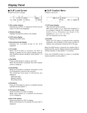
...] button is pressed, information on display is loaded into the current display channel and simplified manual operation screen pattern 1 is restored. Start time code Material duration Recording format 8 [F5] BACK Press the [F5] button to return to simplified manual operation screen pattern 1. 9 Previous CLIP display Shows that there is a CLIP to display. When cursor button [#] is pressed, the previous CLIP is displayed. : Next CLIP display Shows that there is a CLIP to display. change the...
...] button is pressed, information on display is loaded into the current display channel and simplified manual operation screen pattern 1 is restored. Start time code Material duration Recording format 8 [F5] BACK Press the [F5] button to return to simplified manual operation screen pattern 1. 9 Previous CLIP display Shows that there is a CLIP to display. When cursor button [#] is pressed, the previous CLIP is displayed. : Next CLIP display Shows that there is a CLIP to display. change the...

AJHDR150 User Guide
Page 30
...] button is pressed, change is made in local mode. (XX) F.Panel Sel. Up too 100 errors stored. $ Error Log Detailed Display Screen Shows details of input/output boards is in the following format: error type, channel number, error generation point, error content, optional data. Remove the cause of the warning generation. 20: Running can be continued. Error (10-00-0310-1305-0000) F5:MAIN4 O Cannot control from external controller because control...
...] button is pressed, change is made in local mode. (XX) F.Panel Sel. Up too 100 errors stored. $ Error Log Detailed Display Screen Shows details of input/output boards is in the following format: error type, channel number, error generation point, error content, optional data. Remove the cause of the warning generation. 20: Running can be continued. Error (10-00-0310-1305-0000) F5:MAIN4 O Cannot control from external controller because control...

AJHDR150 User Guide
Page 31
...cables are plugged in place using the coin screws. The number and types of connectors differs depending on the type of the four channels. Consult your dealer for connection... properly when reassembling the unit later. 3. Unplug the two SDTI flat cables from the IF board....cables 31 Remove the top panel. 2. Connect the connector panel (packed together with the optional board) to note the connector locations so you can be sure the power cord is required for any or all of board concerned. Reconnect the two SDTI flat cables to the slots marked "F3" on setting and installing...
...cables are plugged in place using the coin screws. The number and types of connectors differs depending on the type of the four channels. Consult your dealer for connection... properly when reassembling the unit later. 3. Unplug the two SDTI flat cables from the IF board....cables 31 Remove the top panel. 2. Connect the connector panel (packed together with the optional board) to note the connector locations so you can be sure the power cord is required for any or all of board concerned. Reconnect the two SDTI flat cables to the slots marked "F3" on setting and installing...

AJHDR150 User Guide
Page 37
... the power before turning it back on the display panel or using O Have the cables been connected properly? O There is no audio output during playback at speeds lower than 1a speed. $ Video recording stops at least 10 seconds after the operation LED has lighted. O Is there anything wrong with the input signal? after turning off ? O Is the server mode set to the HDD delayed? O Do the installed fuses have...
... the power before turning it back on the display panel or using O Have the cables been connected properly? O There is no audio output during playback at speeds lower than 1a speed. $ Video recording stops at least 10 seconds after the operation LED has lighted. O Is there anything wrong with the input signal? after turning off ? O Is the server mode set to the HDD delayed? O Do the installed fuses have...

AJHDR150 User Guide
Page 40
... MHz OS: Windows NT 4.0 (English version) Memory: 128 MB System HDD: 9 GB a2 units Data HDD (Optional): 36 GB a9 units Recording time: 20 hours (calculated at DVCPRO 25 Mbps) Recording format: DVCPRO 25 Mbps, DVCPRO 50 Mbps, DVCPRO P, DVCPRO HD Recording content: Digital video, Time code (subcode domain), Digital audio CLIP count: Maximum 5000 CLIP length: 1 second minimum 20 hours maximum (calculated at DVCPRO 25 Mbps) [Control Component] RS-422A: 4 channel (D-SUB, 9 pin) RS...
... MHz OS: Windows NT 4.0 (English version) Memory: 128 MB System HDD: 9 GB a2 units Data HDD (Optional): 36 GB a9 units Recording time: 20 hours (calculated at DVCPRO 25 Mbps) Recording format: DVCPRO 25 Mbps, DVCPRO 50 Mbps, DVCPRO P, DVCPRO HD Recording content: Digital video, Time code (subcode domain), Digital audio CLIP count: Maximum 5000 CLIP length: 1 second minimum 20 hours maximum (calculated at DVCPRO 25 Mbps) [Control Component] RS-422A: 4 channel (D-SUB, 9 pin) RS...


