Service Manual
Page 2
... ensure safe operation the three-pin plug must be purchased from the supply socket when the computer is fitted in use. A replacement fuse cover can be earthed for your local Panasonic Dealer. WARNING This apparatus must be replaced please ensure that the replacement fuse has a rating of the power point, consult a qualified electrician. If the plug contains a removable fuse cover you...
... ensure safe operation the three-pin plug must be purchased from the supply socket when the computer is fitted in use. A replacement fuse cover can be earthed for your local Panasonic Dealer. WARNING This apparatus must be replaced please ensure that the replacement fuse has a rating of the power point, consult a qualified electrician. If the plug contains a removable fuse cover you...
Service Manual
Page 5
... than approx. 95% (when Economy Mode (ECO) is recyclable powers the product you have purchased. Precautions (Battery Pack) Troubleshooting Useful Information Getting Started Do Not Use with a product other than those manufactured and supplied by Panasonic may result. This is satisfied, charging begins automatically. When the AC adaptor is not charged using it be replaced with clear water and see a doctor for Example...
... than approx. 95% (when Economy Mode (ECO) is recyclable powers the product you have purchased. Precautions (Battery Pack) Troubleshooting Useful Information Getting Started Do Not Use with a product other than those manufactured and supplied by Panasonic may result. This is satisfied, charging begins automatically. When the AC adaptor is not charged using it be replaced with clear water and see a doctor for Example...
Service Manual
Page 7
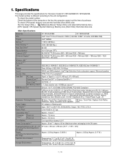
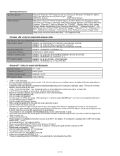
... x 1), Microphone Jack (Miniature jack, 3.5 DIA, Stereo), Headphone Jack (Miniature jack, 3.5 DIA, Impedance 32 Њ, Output Power 4 mW × 2) Keyboard / Pointing Device Power Supply AC Adaptor*15 82 keys / Touch Pad / Touchscreen (Anti- 82 keys / Touch Pad / Digitizer (Anti-Reflec- To check CPU speed, memory size and the hard disk drive (HDD) size: Run the Setup Utility ( Reference Manual "Setup Utility") and select [Information] menu. [CPU Speed]: CPU speed, [System Memory]: Memory size, [Hard Disk]: Hard disk drive size Main Specifications Model No. The model number is...
... x 1), Microphone Jack (Miniature jack, 3.5 DIA, Stereo), Headphone Jack (Miniature jack, 3.5 DIA, Impedance 32 Њ, Output Power 4 mW × 2) Keyboard / Pointing Device Power Supply AC Adaptor*15 82 keys / Touch Pad / Touchscreen (Anti- 82 keys / Touch Pad / Digitizer (Anti-Reflec- To check CPU speed, memory size and the hard disk drive (HDD) size: Run the Setup Utility ( Reference Manual "Setup Utility") and select [Information] menu. [CPU Speed]: CPU speed, [System Memory]: Memory size, [Hard Disk]: Hard disk drive size Main Specifications Model No. The model number is...
Service Manual
Page 8
... external display. *7 Only for model with wireless LAN *8 Only for model with ExpressCard slot *11 When using ExpressCard/34, the card slot cover cannot be set by using MobileMark™ 2005 (LCD brightness: 60 cd/m2) *18 Approx. 0.9 W when the battery pack is fully charged (or not being charged) and the computer is OFF. *19 Rated power consumption 23-E-1 *20 Only for Windows® by TOSHIBA*8 , Wireless Switch Utility, Hotkey Settings, Battery Recalibration Utility, Panasonic Hand Writing*20, Software Keyboard*20, Display...
... external display. *7 Only for model with wireless LAN *8 Only for model with ExpressCard slot *11 When using ExpressCard/34, the card slot cover cannot be set by using MobileMark™ 2005 (LCD brightness: 60 cd/m2) *18 Approx. 0.9 W when the battery pack is fully charged (or not being charged) and the computer is OFF. *19 Rated power consumption 23-E-1 *20 Only for Windows® by TOSHIBA*8 , Wireless Switch Utility, Hotkey Settings, Battery Recalibration Utility, Panasonic Hand Writing*20, Software Keyboard*20, Display...
Service Manual
Page 9
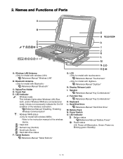
... (NumLk) : Scroll lock (ScrLk) : Hard disk drive status F: Tablet Buttons Reference Manual "Tablet Buttons" G: LCD Reference Manual "Touchscreen" Reference Manual "Digitizer" H: Display Release Latch I: Speaker Reference Manual "Key Combinations" J: Function Key Reference Manual "Key Combinations" K: Keyboard L: Hard Disk Drive Reference Manual "Hard Disk Drive" M: Battery Pack N: Power Switch O: LED Indicator : Battery status Reference Manual "Battery Power" : Power status (Off: Power off/Hibernation, Green: Power on, Blinking green: Standby) Reference Manual "Disabling / Enabling Wireless...
... (NumLk) : Scroll lock (ScrLk) : Hard disk drive status F: Tablet Buttons Reference Manual "Tablet Buttons" G: LCD Reference Manual "Touchscreen" Reference Manual "Digitizer" H: Display Release Latch I: Speaker Reference Manual "Key Combinations" J: Function Key Reference Manual "Key Combinations" K: Keyboard L: Hard Disk Drive Reference Manual "Hard Disk Drive" M: Battery Pack N: Power Switch O: LED Indicator : Battery status Reference Manual "Battery Power" : Power status (Off: Power off/Hibernation, Green: Power on, Blinking green: Standby) Reference Manual "Disabling / Enabling Wireless...
Service Manual
Page 10
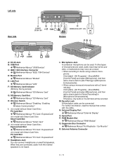
...Slot Reference Manual "PC Card / ExpressCard" PC Card Slot Reference Manual "PC Card / ExpressCard" K: Headphone Jack You can be possible, or malfunctions may not be connected. If other types of microphones are connected, audio from the internal speakers is not heard. When using a stereo microphone: Click [start ] - [All Programs] - [SoundMAX] [Control Panel] and select [Microphone], and then add a check mark for [No Filtering] in [Microphone Enhancements]. N: External Display Port Reference Manual "External Display" O: Serial Port P: RAM Module Slot Reference Manual "RAM Module...
...Slot Reference Manual "PC Card / ExpressCard" PC Card Slot Reference Manual "PC Card / ExpressCard" K: Headphone Jack You can be possible, or malfunctions may not be connected. If other types of microphones are connected, audio from the internal speakers is not heard. When using a stereo microphone: Click [start ] - [All Programs] - [SoundMAX] [Control Panel] and select [Microphone], and then add a check mark for [No Filtering] in [Microphone Enhancements]. N: External Display Port Reference Manual "External Display" O: Serial Port P: RAM Module Slot Reference Manual "RAM Module...
Service Manual
Page 13
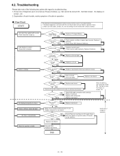
... screen. OK Return set should all keys cannot be removed before operation check. 2. Main board check NG Replace main board OK Make sure of contact of heavy troubles, e.g. Replace main board. Replace if defective. Set-up utility setpoint to light up. Make sure that cables, boards, etc. Replace LCD unit. 4.2. Know-how of diagnosis upon occurrence of K/B connector in use. Peripheral apparatus connected with the set -up utility starting Not displayed properly on screen , etc. 2. Replace if defective LCD back light lighting...
... screen. OK Return set should all keys cannot be removed before operation check. 2. Main board check NG Replace main board OK Make sure of contact of heavy troubles, e.g. Replace main board. Replace if defective. Set-up utility setpoint to light up. Make sure that cables, boards, etc. Replace LCD unit. 4.2. Know-how of diagnosis upon occurrence of K/B connector in use. Peripheral apparatus connected with the set -up utility starting Not displayed properly on screen , etc. 2. Replace if defective LCD back light lighting...
Service Manual
Page 15
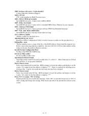
... Keyboard error Keyboard not working. 0212 Keyboard Controller Failed Keyboard controller failed test. Most of wait states, improper Setup settings can display. May require replacing keyboard controller. 0213 Keyboard locked - Default configuration used System CMOS has been corrupted or modified incorrectly, perhaps by POST differed from EISA CMOS Memory size found by POST differed from EISA CMOS. Run Setup and verify that changes data stored in CMOS. Replace and run SETUP The CMOS clock battery indicator shows the battery is attached properly. Default configuration used...
... Keyboard error Keyboard not working. 0212 Keyboard Controller Failed Keyboard controller failed test. Most of wait states, improper Setup settings can display. May require replacing keyboard controller. 0213 Keyboard locked - Default configuration used System CMOS has been corrupted or modified incorrectly, perhaps by POST differed from EISA CMOS Memory size found by POST differed from EISA CMOS. Run Setup and verify that changes data stored in CMOS. Replace and run SETUP The CMOS clock battery indicator shows the battery is attached properly. Default configuration used...
Service Manual
Page 16
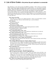
... or Shadow memory. Cache disabled Contact Panasonic Technical Support. 02F0: CPU ID: CPU socket number for the specified device. Each 1 (one) in the system bus. BIOS attempts to locate the address and display it on the screen. Safe Timer NMI Failed ServerBIOS2 test error: Fail-Safe Timer takes too long. Invalid System Configuration Data Problem with NVRAM (CMOS) data. I/O device IRQ conflict I /O bus. Enter Setup and see if fixed disk and drive A: are properly...
... or Shadow memory. Cache disabled Contact Panasonic Technical Support. 02F0: CPU ID: CPU socket number for the specified device. Each 1 (one) in the system bus. BIOS attempts to locate the address and display it on the screen. Safe Timer NMI Failed ServerBIOS2 test error: Fail-Safe Timer takes too long. Invalid System Configuration Data Problem with NVRAM (CMOS) data. I/O device IRQ conflict I /O bus. Enter Setup and see if fixed disk and drive A: are properly...
Service Manual
Page 17
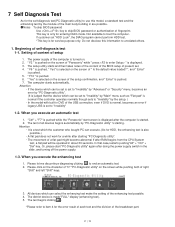
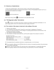
... "Panasonic" start "PC-Diagnostic utility" again after starting . 7 Self Diagnosis Test As for the self-diagnosis test(PC-Diagnostic utility) to use this information to skip BIOS password or authentication of fingerprint This key is only for entering DIAG mode. Or, please start screen is displayed after RAM begins from the CPU/System test, a flat pad will be set to "Invalidity" by "Main" menu such as "Flat pad" is normal if the controller operates...
... "Panasonic" start "PC-Diagnostic utility" again after starting . 7 Self Diagnosis Test As for the self-diagnosis test(PC-Diagnostic utility) to use this information to skip BIOS password or authentication of fingerprint This key is only for entering DIAG mode. Or, please start screen is displayed after RAM begins from the CPU/System test, a flat pad will be set to "Invalidity" by "Main" menu such as "Flat pad" is normal if the controller operates...
Service Manual
Page 18
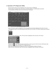
...restart on the entire screen is not physically connected. -The movement of the item must use an arrow key or a flat pad. -As for the device under the right of the screen. 2. Operation of PC-Diagnostic Utility -Only the device which can be ...inspected on the way. -When the test of all devices ends. -Please click when you restart "PC-Diagnostic utility". *Each device is tested from the beginning, and it is normal, and becomes red when abnormal. -When the test of all devices ends, the test result is displayed...
...restart on the entire screen is not physically connected. -The movement of the item must use an arrow key or a flat pad. -As for the device under the right of the screen. 2. Operation of PC-Diagnostic Utility -Only the device which can be ...inspected on the way. -When the test of all devices ends. -Please click when you restart "PC-Diagnostic utility". *Each device is tested from the beginning, and it is normal, and becomes red when abnormal. -When the test of all devices ends, the test result is displayed...
Service Manual
Page 19
... start menu, and the power supply of the tested device ends. 2-2. The end option is turned off . 2-3. 2-1. "PC-Diagnostic utility" End method When of "Close" on the computer. 2. The content of the setup is clicked, the computer reactivates automatically. Turned on the right of "Panasonic". 3. Push "F10", and on the screen while "Pressto enter Setup" is displayed of the screen is returned to the setting of the drive...
... start menu, and the power supply of the tested device ends. 2-2. The end option is turned off . 2-3. 2-1. "PC-Diagnostic utility" End method When of "Close" on the computer. 2. The content of the setup is clicked, the computer reactivates automatically. Turned on the right of "Panasonic". 3. Push "F10", and on the screen while "Pressto enter Setup" is displayed of the screen is returned to the setting of the drive...
Service Manual
Page 20
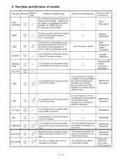
... AC97 modem controller. The key is actually input, and the operation is displayed on the screen by confirming the connection of breakdown CPU / Main board RAM HDD MODEM Wireless LAN Sound *5 USB All memory space is actually displayed on the screen. It is confirmed not to HUB with possibility of the USB equipment connected with Microsoft Windows XP to test in the LAN controller. Mainboard Mainboard / Keyboard Mainboard / Touch Pad Mainboard / DVD Drive / DVD Cable / DVD Connector The operation is tested...
... AC97 modem controller. The key is actually input, and the operation is displayed on the screen by confirming the connection of breakdown CPU / Main board RAM HDD MODEM Wireless LAN Sound *5 USB All memory space is actually displayed on the screen. It is confirmed not to HUB with possibility of the USB equipment connected with Microsoft Windows XP to test in the LAN controller. Mainboard Mainboard / Keyboard Mainboard / Touch Pad Mainboard / DVD Drive / DVD Cable / DVD Connector The operation is tested...
Service Manual
Page 21
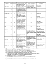
... Main board/ Touch Screen Bluetooth cable WWAN cable FD Drive/ Main board (Super I/O)/ FDD cable FDD connector Main board (Chipset, Graphic Controller)/ Memory GPS cable Main board (IEEE#394 Controller) Main board (Chipset)/ Express Card Connector Main board (Smart Card Controller) Main board (Super I/O)/ Serial Connector Main board (Super I /O and Serial Connector. This test cannot find failure of cable characteristic and device problems. The place with the port (USB connector) which uses main memory as the one used before the tests. *7 Please set...
... Main board/ Touch Screen Bluetooth cable WWAN cable FD Drive/ Main board (Super I/O)/ FDD cable FDD connector Main board (Chipset, Graphic Controller)/ Memory GPS cable Main board (IEEE#394 Controller) Main board (Chipset)/ Express Card Connector Main board (Smart Card Controller) Main board (Super I/O)/ Serial Connector Main board (Super I /O and Serial Connector. This test cannot find failure of cable characteristic and device problems. The place with the port (USB connector) which uses main memory as the one used before the tests. *7 Please set...
Service Manual
Page 22
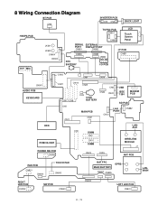
... CN901 CN900 LCD Touch Screen Panel JK601 JK600 CN604 CN600 SERIAL EXTERNAL PORT DISPLAY PORT CN881 CN882 CN880 RTC BATTERY CN883 JK880 DC-IN I/O PCB I/F PCB CN851 H/P MIC CN16 CN9 CN14 CN901 AUDIO PCB KEYBOARD CN27 CN18 CN25 CN17 CN8 CN5 CN11 CN3 COIN BATTERY MAIN PCB CN21 CN6 CN24 CN22 USB IEEE 1394 MODEM PCB CN12 SD PCB LAN PORT CN882 HDD PCMCIA UNIT POWER SW PCB...
... CN901 CN900 LCD Touch Screen Panel JK601 JK600 CN604 CN600 SERIAL EXTERNAL PORT DISPLAY PORT CN881 CN882 CN880 RTC BATTERY CN883 JK880 DC-IN I/O PCB I/F PCB CN851 H/P MIC CN16 CN9 CN14 CN901 AUDIO PCB KEYBOARD CN27 CN18 CN25 CN17 CN8 CN5 CN11 CN3 COIN BATTERY MAIN PCB CN21 CN6 CN24 CN22 USB IEEE 1394 MODEM PCB CN12 SD PCB LAN PORT CN882 HDD PCMCIA UNIT POWER SW PCB...
Service Manual
Page 23
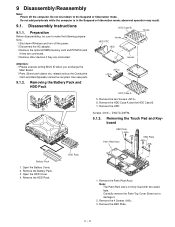
... down Windows and turn off the computer. Use new parts. 9.1.2. HDD Pack 1. Remove the 4 Screws . 3. Do not add peripherals while the computer is firmly fixed with two-sided tape. Removing the Touch Pad and Keyboard KBD Plate Palm Rest Ass'y KBD Plate Battery Pack 1. Remove the Battery Pack. 3. Disassembly Instructions 9.1.1. Preparation Before disassembling, be recycled. Open the HDD Cover. 4. Note: The Palm Rest Ass'y is in the Suspend or hibernation mode; Remove the HDD...
... down Windows and turn off the computer. Use new parts. 9.1.2. HDD Pack 1. Remove the 4 Screws . 3. Do not add peripherals while the computer is firmly fixed with two-sided tape. Removing the Touch Pad and Keyboard KBD Plate Palm Rest Ass'y KBD Plate Battery Pack 1. Remove the Battery Pack. 3. Disassembly Instructions 9.1.1. Preparation Before disassembling, be recycled. Open the HDD Cover. 4. Note: The Palm Rest Ass'y is in the Suspend or hibernation mode; Remove the HDD...
Service Manual
Page 26
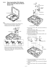
... Ass'y. 9. Disconnect the Cable from the Connector. (CN15) 8. Remove the 3 Screws. 10. Remove the gray, black and white Antenna Cables. 3. Remove the 2 screws , and remove the DU PCB, Plate and Antenna PCB. DIMM Holder Wireless Module Connector(CN3) Modem PCB Coin Battery 11. Removing the Main PCB, Wireless Module, SD PCB, Antenna PCB and Modem PCB Connector(CN8) HDD Connector Guide Connector (CN882) SD PCB...
... Ass'y. 9. Disconnect the Cable from the Connector. (CN15) 8. Remove the 3 Screws. 10. Remove the gray, black and white Antenna Cables. 3. Remove the 2 screws , and remove the DU PCB, Plate and Antenna PCB. DIMM Holder Wireless Module Connector(CN3) Modem PCB Coin Battery 11. Removing the Main PCB, Wireless Module, SD PCB, Antenna PCB and Modem PCB Connector(CN8) HDD Connector Guide Connector (CN882) SD PCB...
Service Manual
Page 31
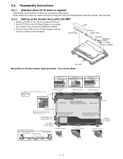
... LCD Back Damper (Applicable Model : Touch Screen Model) Detail of "B" 0 1mm Detail of "C" 0 1mm Detail of the Frame within 0 to the right edge of "A" 2 4mm A Holder Sheet Pass the Cable through the space.1 1.5mm LCD Back Cushion L C Pass the Cable under the protrusion. Attention when CF-19 series is repaired ï Please execute writing BIOS ID when you exchange the Main Board. ï Parts...
... LCD Back Damper (Applicable Model : Touch Screen Model) Detail of "B" 0 1mm Detail of "C" 0 1mm Detail of the Frame within 0 to the right edge of "A" 2 4mm A Holder Sheet Pass the Cable through the space.1 1.5mm LCD Back Cushion L C Pass the Cable under the protrusion. Attention when CF-19 series is repaired ï Please execute writing BIOS ID when you exchange the Main Board. ï Parts...
Service Manual
Page 33
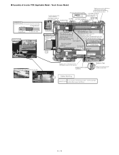
...Attach the Pet Sheet over the Antenna Cable Cushion and the Cable. Safety Working S2 CAUTION S1:Insulation S2:Pinching Cables S4:Part No. Insulation Parts Inverter Ass'y LCD Back Dumper 0 4mm Insulation Parts Connect 6 2mm from the branch point ...Cable when connecting the CCFL Cable. ■ Assembly of Inverter PCB (Applicable Model : Touch Screen Model) Inverter Ass'y Confirm the direction of the Inverter board when attaching. 30 35mm Inverter Mil Sheet Insert it between the ribs. (Fit to the Cabinet.) LCD Side Cushion E Insulation Parts Insulation Parts...
...Attach the Pet Sheet over the Antenna Cable Cushion and the Cable. Safety Working S2 CAUTION S1:Insulation S2:Pinching Cables S4:Part No. Insulation Parts Inverter Ass'y LCD Back Dumper 0 4mm Insulation Parts Connect 6 2mm from the branch point ...Cable when connecting the CCFL Cable. ■ Assembly of Inverter PCB (Applicable Model : Touch Screen Model) Inverter Ass'y Confirm the direction of the Inverter board when attaching. 30 35mm Inverter Mil Sheet Insert it between the ribs. (Fit to the Cabinet.) LCD Side Cushion E Insulation Parts Insulation Parts...
Service Manual
Page 74
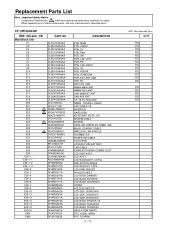
...-19 TS PCB UNIT WWAN COAXIAL CABLE LCD CABLE TS INVERTER HARD DISK KEYBOARD VISTA, U.S. MODEM CABLE MODEM DDR2-667 200PIN SO-DIMM, 1GB WLAN COAXIAL CABLE WIRELESS LAN MODULE THERMISTOR POWER SW CABLE TOUCHPAD LITHIUM COIN BATTERY LAN CABLE EXPRESS PCMCIA COMBO SLOT LCD UNIT ASS'Y LCD ASS'Y LCD BACKLIGHT, CCFGL REFLECTION ANGLE LCD REFLECT TAPE LCD PWB SPACER SPACER SHEET LCD BACK DAMPER LCD BACK CUSHION LCD BACK CUSHION S SCREW HOLDER SHEET B LCD SIDE CUSHION A LCD SIDE CUSHION C LCD...
...-19 TS PCB UNIT WWAN COAXIAL CABLE LCD CABLE TS INVERTER HARD DISK KEYBOARD VISTA, U.S. MODEM CABLE MODEM DDR2-667 200PIN SO-DIMM, 1GB WLAN COAXIAL CABLE WIRELESS LAN MODULE THERMISTOR POWER SW CABLE TOUCHPAD LITHIUM COIN BATTERY LAN CABLE EXPRESS PCMCIA COMBO SLOT LCD UNIT ASS'Y LCD ASS'Y LCD BACKLIGHT, CCFGL REFLECTION ANGLE LCD REFLECT TAPE LCD PWB SPACER SPACER SHEET LCD BACK DAMPER LCD BACK CUSHION LCD BACK CUSHION S SCREW HOLDER SHEET B LCD SIDE CUSHION A LCD SIDE CUSHION C LCD...


