Owner Manual
Page 1
AV Receiver TX-NR807 HT-RC180 Instruction Manual Thank you to obtain optimum performance and listening enjoyment from your new AV Receiver. Please retain this manual for purchasing an Onkyo AV Receiver. Contents Introduction 2 Connection 18 Turning On & First Time Setup .....42 Basic Operations 60 Using the Listening Modes ........74 Advanced Setup 84 NET 107 Multi Zone 115 Controlling Other Components...
AV Receiver TX-NR807 HT-RC180 Instruction Manual Thank you to obtain optimum performance and listening enjoyment from your new AV Receiver. Please retain this manual for purchasing an Onkyo AV Receiver. Contents Introduction 2 Connection 18 Turning On & First Time Setup .....42 Basic Operations 60 Using the Listening Modes ........74 Advanced Setup 84 NET 107 Multi Zone 115 Controlling Other Components...
Owner Manual
Page 5
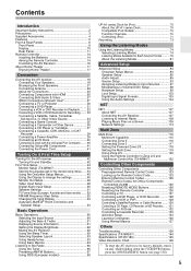
...Connector....... 40 Connecting Onkyo V Components 41 Connecting the Power Cord 41 Turning On & First Time Setup Turning On the AV receiver 42 Turning On and Standby 42 First Time Setup 43 Monitor Setup (TX-NR807 43 Selecting the...AV Receiver 107 Listening to Internet Radio 108 Playing Music Files on a Server 109 Network Settings 113 Multi Zone Multi Zone 115 Multiroom Capability 115 Connecting Zone 2 116 Connecting Zone 3 117 Setting the Powered Zone 2/3 118 Setting the Multi Zone 119 Using Zone 2/3 120 Using the Remote Controller in Zone 2/3 and Multiroom Control Kits (TX-NR807...
...Connector....... 40 Connecting Onkyo V Components 41 Connecting the Power Cord 41 Turning On & First Time Setup Turning On the AV receiver 42 Turning On and Standby 42 First Time Setup 43 Monitor Setup (TX-NR807 43 Selecting the...AV Receiver 107 Listening to Internet Radio 108 Playing Music Files on a Server 109 Network Settings 113 Multi Zone Multi Zone 115 Multiroom Capability 115 Connecting Zone 2 116 Connecting Zone 3 117 Setting the Powered Zone 2/3 118 Setting the Multi Zone 119 Using Zone 2/3 120 Using the Remote Controller in Zone 2/3 and Multiroom Control Kits (TX-NR807...
Owner Manual
Page 6
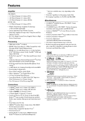
...on the region. • Network Capability for Streaming Audio Files • Bi-Amping Capability for FL/FR with SBL/SBR Miscellaneous • 40 SIRIUS*8/AM/FM Presets (TX-NR807: North American models) • 40 AM/FM Presets (TX-NR807: Taiwan, European, Australian and...Sensation are trademarks or registered trademarks of Dolby Laboratories. *4. Manufactured under U.S. To receive HD Radio broadcasts, you must install an Onkyo UP-HT1 HD Radio tuner module (sold separately). *7. All rights reserved. *2. Features Amplifier (TX-NR807) • 135 Watts/Channel @ 8 ohms (FTC) • 180 Watts...
...on the region. • Network Capability for Streaming Audio Files • Bi-Amping Capability for FL/FR with SBL/SBR Miscellaneous • 40 SIRIUS*8/AM/FM Presets (TX-NR807: North American models) • 40 AM/FM Presets (TX-NR807: Taiwan, European, Australian and...Sensation are trademarks or registered trademarks of Dolby Laboratories. *4. Manufactured under U.S. To receive HD Radio broadcasts, you must install an Onkyo UP-HT1 HD Radio tuner module (sold separately). *7. All rights reserved. *2. Features Amplifier (TX-NR807) • 135 Watts/Channel @ 8 ohms (FTC) • 180 Watts...
Owner Manual
Page 8
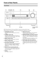
...These buttons are not shown here for each item. See "Volume Setup" on page 10. Pressing this mode is selected. E ZONE 3 indicator (120) This indicator lights up when the AV receiver is in parentheses show where you can also be displayed as an absolute value. H Display See "Display" on page 98. I... data to On or Standby. J MASTER VOLUME control (60) and indicator This control is selected. The indicator lights up when Zone 2 is used to adjust the volume of the AV receiver to -2 dB, -81.5 dB through +18.0 dB (relative display). The page numbers in Standby mode, and it . ...
...These buttons are not shown here for each item. See "Volume Setup" on page 10. Pressing this mode is selected. E ZONE 3 indicator (120) This indicator lights up when the AV receiver is in parentheses show where you can also be displayed as an absolute value. H Display See "Display" on page 98. I... data to On or Standby. J MASTER VOLUME control (60) and indicator This control is selected. The indicator lights up when Zone 2 is used to adjust the volume of the AV receiver to -2 dB, -81.5 dB through +18.0 dB (relative display). The page numbers in Standby mode, and it . ...

Owner Manual
Page 9
...VW X Y Z[ (European, Australian and Asian models) " R The page numbers in areas where RDS broadcasts are used when turn on the connected TV. The [ZONE 3] button is also used with the onscreen setup menus. N TONE button (61, 121) Used to set items. The [ENTER] button is used to the previously... the display brightness. M ZONE 2, ZONE 3, and OFF buttons (120) The [ZONE 2] button is used when storing or deleting radio presets. L PHONES jack (63) This 1/4-inch phone jack is used to select the Auto or Manual tuning mode. P MONITOR OUT button (TX-NR807) (43) Used to ...
...VW X Y Z[ (European, Australian and Asian models) " R The page numbers in areas where RDS broadcasts are used when turn on the connected TV. The [ZONE 3] button is also used with the onscreen setup menus. N TONE button (61, 121) Used to set items. The [ENTER] button is used to the previously... the display brightness. M ZONE 2, ZONE 3, and OFF buttons (120) The [ZONE 2] button is used when storing or deleting radio presets. L PHONES jack (63) This 1/4-inch phone jack is used to select the Auto or Manual tuning mode. P MONITOR OUT button (TX-NR807) (43) Used to ...

Owner Manual
Page 10
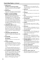
... off . Y AUX INPUT (36) This input can establish a connection to OFF, the AV receiver is selected. It must be used . L M NO F NETWORK indicator (108) Lights up when a pair of headphones are jacks for Zone 2 or Zone 3. [ MUSIC OPTIMIZER button (105) Turns the Music Optimizer on . J Headphone indicator ...(63) Lights up when the AV receiver can be set to ON to set to the ...
... off . Y AUX INPUT (36) This input can establish a connection to OFF, the AV receiver is selected. It must be used . L M NO F NETWORK indicator (108) Lights up when a pair of headphones are jacks for Zone 2 or Zone 3. [ MUSIC OPTIMIZER button (105) Turns the Music Optimizer on . J Headphone indicator ...(63) Lights up when the AV receiver can be set to ON to set to the ...
Owner Manual
Page 12
... 2-channel analog audio output. Input jacks include S-Video, composite video, and analog audio. O 12V TRIGGER OUT ZONE 2 (TX-NR807) This output can be connected to use the AV receiver solely as a preamplifier. Input jacks include S-Video, composite video, and analog audio. You can connect a cable...connected to the IR IN jack, allowing you to a video input on amplifiers in Zone 2. When Zone 3 is output. 12V TRIGGER OUT ZONE 3 (TX-NR807) This output can be connected to control the AV receiver while you can connect a game console, etc. Input and output jacks include S-...
... 2-channel analog audio output. Input jacks include S-Video, composite video, and analog audio. O 12V TRIGGER OUT ZONE 2 (TX-NR807) This output can be connected to use the AV receiver solely as a preamplifier. Input jacks include S-Video, composite video, and analog audio. You can connect a cable...connected to the IR IN jack, allowing you to a video input on amplifiers in Zone 2. When Zone 3 is output. 12V TRIGGER OUT ZONE 3 (TX-NR807) This output can be connected to control the AV receiver while you can connect a game console, etc. Input and output jacks include S-...

Owner Manual
Page 13
See "Bi-amping the Front Speakers" on page 117. See pages 18-41 for connecting the front L/R, center, surround/zone 3 L/R, surround back/ zone 2 L/R, front high L/R, and front wide L/R speakers. The SURR BACK/ZONE 2 L/R terminals can be used with surround back speakers respectively, or used to biamp the front speakers. The FRONT L/R and SURR BACK...
See "Bi-amping the Front Speakers" on page 117. See pages 18-41 for connecting the front L/R, center, surround/zone 3 L/R, surround back/ zone 2 L/R, front high L/R, and front wide L/R speakers. The SURR BACK/ZONE 2 L/R terminals can be used with surround back speakers respectively, or used to biamp the front speakers. The FRONT L/R and SURR BACK...
Owner Manual
Page 18
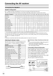
...-coded and you should use , a powered subwoofer is to an input on the amp. Then all black). Connecting a Powered Subwoofer Using a suitable cable, connect the AV receiver's PRE OUT: SUBWOOFER to match the color of speakers: 2 3 4 5 6 7 7 7 8 8 9 9 9 10 11 Front left Front right Center ✓ Surround ... You can do is recommended for a really powerful and solid bass. To get the best from each label to the SURR BACK/ZONE 2 L terminals. If your subwoofer is output from your powered subwoofer, as shown. The same signal is unpowered and you're ...
...-coded and you should use , a powered subwoofer is to an input on the amp. Then all black). Connecting a Powered Subwoofer Using a suitable cable, connect the AV receiver's PRE OUT: SUBWOOFER to match the color of speakers: 2 3 4 5 6 7 7 7 8 8 9 9 9 10 11 Front left Front right Center ✓ Surround ... You can do is recommended for a really powerful and solid bass. To get the best from each label to the SURR BACK/ZONE 2 L terminals. If your subwoofer is output from your powered subwoofer, as shown. The same signal is unpowered and you're ...

Owner Manual
Page 19
... terminals, and negative (-) terminals only to short the positive and negative wires. Surround left speaker 3. Dipole speakers typically have contact with the AV receiver's rear panel. In other , as shown. Do not connect them to several terminals. 19 Surround back left speaker 12.Front wide right... speaker Speaker Connection Precautions Read the following before making any of the wire does not have an arrow printed on them to the SURR BACK/ZONE 2 L/R, FRONT WIDE L/R, or FRONT HIGH L/R terminals. • Be careful not to negative (-) terminals. Center speaker 4. Front high ...
... terminals, and negative (-) terminals only to short the positive and negative wires. Surround left speaker 3. Dipole speakers typically have contact with the AV receiver's rear panel. In other , as shown. Do not connect them to several terminals. 19 Surround back left speaker 12.Front wide right... speaker Speaker Connection Precautions Read the following before making any of the wire does not have an arrow printed on them to the SURR BACK/ZONE 2 L/R, FRONT WIDE L/R, or FRONT HIGH L/R terminals. • Be careful not to negative (-) terminals. Center speaker 4. Front high ...

Owner Manual
Page 20
...mm) 3 Fully insert the bare wires. 4 Screw the terminal tight. The following illustration shows which speaker should be connected to the SURR BACK/ZONE 2 L terminals. Front high right speaker Front wide right speaker Front right speaker Front left speaker Front wide left speaker Front high left speaker ...Center speaker Surround right speaker 20 Surround back right speaker Surround back left speaker Surround left speaker Connecting the AV receiver-Continued Connecting the Speaker Cables 1 Strip 1/2" to 5/8" (12 to 15 mm) of insulation from the ends of terminals.
...mm) 3 Fully insert the bare wires. 4 Screw the terminal tight. The following illustration shows which speaker should be connected to the SURR BACK/ZONE 2 L terminals. Front high right speaker Front wide right speaker Front right speaker Front left speaker Front wide left speaker Front high left speaker ...Center speaker Surround right speaker 20 Surround back right speaker Surround back left speaker Surround left speaker Connecting the AV receiver-Continued Connecting the Speaker Cables 1 Strip 1/2" to 5/8" (12 to 15 mm) of insulation from the ends of terminals.

Owner Manual
Page 21
... provide separate tweeter and woofer feeds for a pair of front speakers that support bi-amping. And connect the AV receiver's SURR BACK/ZONE 2 R negative (-) terminal to the right speaker's negative (-) Tweeter (high) terminal. 3 Connect the AV receiver's FRONT L positive (+) terminal to remove the jumper bars that link the speakers' tweeter (high) and woofer (low) terminals...
... provide separate tweeter and woofer feeds for a pair of front speakers that support bi-amping. And connect the AV receiver's SURR BACK/ZONE 2 R negative (-) terminal to the right speaker's negative (-) Tweeter (high) terminal. 3 Connect the AV receiver's FRONT L positive (+) terminal to remove the jumper bars that link the speakers' tweeter (high) and woofer (low) terminals...

Owner Manual
Page 30
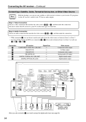
... an audio connection that matches your TV ( A , B , or C ), and then make the connection. • With connection a , you need to TV programs through the AV receiver (see page 50). Hint! Step 1: Video Connection Choose a video connection that matches your TV ( a , b , or c ), and then make the connection. When you use... or c , you can listen to and record audio from your TV or listen in Zone 2 or Zone 3. • To enjoy Dolby Digital and DTS, use connection b or c . (To record or listen in Zone 2 or Zone 3 as well, use its tuner to listen to assign the digital audio input (see ...
... an audio connection that matches your TV ( A , B , or C ), and then make the connection. • With connection a , you need to TV programs through the AV receiver (see page 50). Hint! Step 1: Video Connection Choose a video connection that matches your TV ( a , b , or c ), and then make the connection. When you use... or c , you can listen to and record audio from your TV or listen in Zone 2 or Zone 3. • To enjoy Dolby Digital and DTS, use connection b or c . (To record or listen in Zone 2 or Zone 3 as well, use its tuner to listen to assign the digital audio input (see ...

Owner Manual
Page 31
...and right outputs and multichannel left and right outputs, be sure to use the main left and right outputs for HDMI connection information. Connection A B C a b c AV receiver COMPONENT VIDEO IN 1 (DVD/BD) DVD/BD IN S DVD/BD IN V DVD/BD IN L/R DIGITAL COAXIAL IN 1 (DVD/BD) DIGITAL OPTICAL IN 1 (GAME... DVD player or listen in Zone 2 or Zone 3. • To enjoy Dolby Digital and DTS, use connection b or c . (To record or listen in Zone 2 or Zone 3 as well, use connection c , you need to your TV via the same type of connection. You must connect the AV receiver to assign the digital audio input...
...and right outputs and multichannel left and right outputs, be sure to use the main left and right outputs for HDMI connection information. Connection A B C a b c AV receiver COMPONENT VIDEO IN 1 (DVD/BD) DVD/BD IN S DVD/BD IN V DVD/BD IN L/R DIGITAL COAXIAL IN 1 (DVD/BD) DIGITAL OPTICAL IN 1 (GAME... DVD player or listen in Zone 2 or Zone 3. • To enjoy Dolby Digital and DTS, use connection b or c . (To record or listen in Zone 2 or Zone 3 as well, use connection c , you need to your TV via the same type of connection. You must connect the AV receiver to assign the digital audio input...
Owner Manual
Page 32
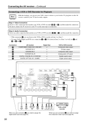
... Digital and DTS, use connection b or c . (To listen in Zone 2 or Zone 3 as well, use your VCR's tuner to listen to assign the digital audio input (see page 49). 32 Step 2: Audio Connection Choose an audio connection that matches your TV via the AV receiver, useful if your VCR or DVD recorder ( a , b , or c ), and...
... Digital and DTS, use connection b or c . (To listen in Zone 2 or Zone 3 as well, use your VCR's tuner to listen to assign the digital audio input (see page 49). 32 Step 2: Audio Connection Choose an audio connection that matches your TV via the AV receiver, useful if your VCR or DVD recorder ( a , b , or c ), and...
Owner Manual
Page 34
...; To enjoy Dolby Digital and DTS, use connection b or c . (To record or listen in Zone 2 or Zone 3 as well, use your satellite or cable receiver to listen to assign the digital audio input (see page 50). 34 Connecting the AV receiver-Continued Connecting a Satellite, Cable, Terrestrial Set-top box, or Other Video Source Hint! With...
...; To enjoy Dolby Digital and DTS, use connection b or c . (To record or listen in Zone 2 or Zone 3 as well, use your satellite or cable receiver to listen to assign the digital audio input (see page 50). 34 Connecting the AV receiver-Continued Connecting a Satellite, Cable, Terrestrial Set-top box, or Other Video Source Hint! With...
Owner Manual
Page 35
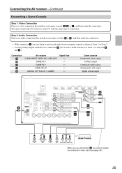
... connection a , you can listen to and record audio from your game console or listen in Zone 2 or Zone 3. • To enjoy Dolby Digital and DTS, use connection b . (To record or listen in Zone 2 or Zone 3 as well, use a and b .) Connection A B C a b AV receiver COMPONENT VIDEO IN 2 (CBL/SAT) GAME IN S GAME IN V GAME IN L/R DIGITAL OPTICAL IN...
... connection a , you can listen to and record audio from your game console or listen in Zone 2 or Zone 3. • To enjoy Dolby Digital and DTS, use connection b . (To record or listen in Zone 2 or Zone 3 as well, use a and b .) Connection A B C a b AV receiver COMPONENT VIDEO IN 2 (CBL/SAT) GAME IN S GAME IN V GAME IN L/R DIGITAL OPTICAL IN...
Owner Manual
Page 37
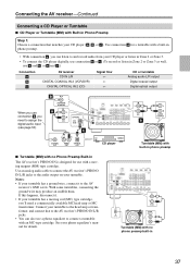
... connection b , you need a commercially available MC head amp or MC transformer. AUDIO OUTPUT L R Turntable (MM) with no Phono Preamp Built-in Zone 2 or Zone 3 as well, use a and b , or a and c .) Connection a b c AV receiver CD IN L/R DIGITAL COAXIAL IN 2 (VCR/DVR) DIGITAL OPTICAL IN 2 (CD) Signal flow ⇐ ⇐ ⇐ CD or turntable Analog audio...
... connection b , you need a commercially available MC head amp or MC transformer. AUDIO OUTPUT L R Turntable (MM) with no Phono Preamp Built-in Zone 2 or Zone 3 as well, use a and b , or a and c .) Connection a b c AV receiver CD IN L/R DIGITAL COAXIAL IN 2 (VCR/DVR) DIGITAL OPTICAL IN 2 (CD) Signal flow ⇐ ⇐ ⇐ CD or turntable Analog audio...

Owner Manual
Page 38
COAXIAL OUT OPTICAL OUT L R AUDIO IN L R AUDIO OUT Cassette, CDR, MD, or DAT recorder 38 Connection a b c AV receiver TV/TAPE IN L/R TV/TAPE OUT L/R DIGITAL COAXIAL IN 3 (CBL/SAT) DIGITAL OPTICAL IN 1 (GAME) Signal flow ⇐ ⇒ ⇐ &#...(CBL/SAT) c OPTICAL IN 1 (GAME) IN a L R TV/TAPE a L R TV/TAPE When you need to assign the digital audio input (see page 50). Connecting the AV receiver-Continued Connecting a Cassette, CDR, MiniDisc, or DAT Recorder Step 1: Choose a connection that matches the recorder ( a , b or c ), and then make the connection. • With...
COAXIAL OUT OPTICAL OUT L R AUDIO IN L R AUDIO OUT Cassette, CDR, MD, or DAT recorder 38 Connection a b c AV receiver TV/TAPE IN L/R TV/TAPE OUT L/R DIGITAL COAXIAL IN 3 (CBL/SAT) DIGITAL OPTICAL IN 1 (GAME) Signal flow ⇐ ⇒ ⇐ &#...(CBL/SAT) c OPTICAL IN 1 (GAME) IN a L R TV/TAPE a L R TV/TAPE When you need to assign the digital audio input (see page 50). Connecting the AV receiver-Continued Connecting a Cassette, CDR, MiniDisc, or DAT Recorder Step 1: Choose a connection that matches the recorder ( a , b or c ), and then make the connection. • With...
Owner Manual
Page 41
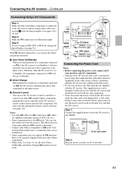
... Cord Notes: • Before connecting the power cord, connect all V functions. Notes: • Use only V cables for use the AV receiver's remote controller to the AV receiver with your other Onkyo components. • While Zone 2 or Zone 3 is connected to control your other manufacturer's components may cause a malfunction. • Some components may not support all of the...
... Cord Notes: • Before connecting the power cord, connect all V functions. Notes: • Use only V cables for use the AV receiver's remote controller to the AV receiver with your other Onkyo components. • While Zone 2 or Zone 3 is connected to control your other manufacturer's components may cause a malfunction. • Some components may not support all of the...


