Owner Manual
Page 4
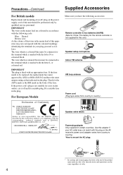
MIYAGI ONKYO EUROPE ELECTRONICS GmbH 1 Speaker Cable 2 FRONT LEFT FRONT LEFT FRONT RIGHT FRONT RIGHT ... the plug on the AV receiver's power cord (adapter varies from country to country.) Speaker cable labels * Power-plug adapter Only supplied in accordance with the corresponding technical standards such as that the ONKYO product described in this instruction...Accessories For British models Replacement and mounting of an AC plug on the power supply cord of this unit.) Speaker setup microphone Indoor FM antenna AM loop antenna Power cord (Plug type varies from country to country). *...
MIYAGI ONKYO EUROPE ELECTRONICS GmbH 1 Speaker Cable 2 FRONT LEFT FRONT LEFT FRONT RIGHT FRONT RIGHT ... the plug on the AV receiver's power cord (adapter varies from country to country.) Speaker cable labels * Power-plug adapter Only supplied in accordance with the corresponding technical standards such as that the ONKYO product described in this instruction...Accessories For British models Replacement and mounting of an AC plug on the power supply cord of this unit.) Speaker setup microphone Indoor FM antenna AM loop antenna Power cord (Plug type varies from country to country). *...
Owner Manual
Page 5
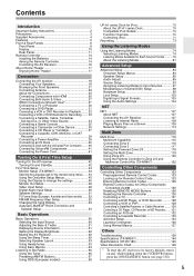
... Connecting Onkyo V Components 41 Connecting the Power Cord 41 Turning On & First Time Setup Turning On the AV receiver 42 Turning On and Standby 42 First Time Setup 43 Monitor Setup (TX-NR807 43 ... Frequency Step Setup 52 Changing the Input Display 53 Audyssey MultEQ® Room Correction and Speaker Setup 54 Basic Operations Basic Operations 60 Selecting the Input Source 60 Adjusting the Bass ...104 NET NET 107 About NET 107 Connecting the AV Receiver 107 Listening to Internet Radio 108 Playing Music Files on a Server 109 Network Settings 113 Multi Zone Multi Zone 115 Multiroom ...
... Connecting Onkyo V Components 41 Connecting the Power Cord 41 Turning On & First Time Setup Turning On the AV receiver 42 Turning On and Standby 42 First Time Setup 43 Monitor Setup (TX-NR807 43 ... Frequency Step Setup 52 Changing the Input Display 53 Audyssey MultEQ® Room Correction and Speaker Setup 54 Basic Operations Basic Operations 60 Selecting the Input Source 60 Adjusting the Bass ...104 NET NET 107 About NET 107 Connecting the AV Receiver 107 Listening to Internet Radio 108 Playing Music Files on a Server 109 Network Settings 113 Multi Zone Multi Zone 115 Multiroom ...
Owner Manual
Page 6
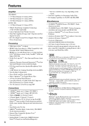
...HT-RC180) • Onkyo for System Control • 6 Digital Inputs (3 Optical/3 Coaxial) • Universal Port for UP-A1 (Dock for Gaming; els) • Dual Subwoofer Pre Out • SIRIUS*8 Satellite Radio Connectivity (TX-NR807: North American models) • Banana Plug-Compatible Speaker Posts*7 • Powered...on the region. • Network Capability for Streaming Audio Files • Bi-Amping Capability for FL/FR with SBL/SBR Miscellaneous • 40 SIRIUS*8/AM/FM Presets (TX-NR807: North American models) • 40 AM/FM Presets (TX-NR807: Taiwan, European, Australian ...
...HT-RC180) • Onkyo for System Control • 6 Digital Inputs (3 Optical/3 Coaxial) • Universal Port for UP-A1 (Dock for Gaming; els) • Dual Subwoofer Pre Out • SIRIUS*8 Satellite Radio Connectivity (TX-NR807: North American models) • Banana Plug-Compatible Speaker Posts*7 • Powered...on the region. • Network Capability for Streaming Audio Files • Bi-Amping Capability for FL/FR with SBL/SBR Miscellaneous • 40 SIRIUS*8/AM/FM Presets (TX-NR807: North American models) • 40 AM/FM Presets (TX-NR807: Taiwan, European, Australian ...

Owner Manual
Page 10
... Bi AMP indicator (21) Lights up when the AV receiver can be set to ON to set to OFF, the AV receiver is set the AV receiver to the media server or internet radio stations. L M NO F NETWORK indicator (108) Lights up when the "Speakers Type(Front)" setting is completely shutdown. G Tuning ... Powered Zone 3 is selected for Zone 2 or Zone 3. [ MUSIC OPTIMIZER button (105) Turns the Music Optimizer on . B Speaker/channel indicators Indicate the speaker channels used . H SLEEP indicator (62) Lights up when Powered Zone 2 is being used to connect a camcorder, game console, ...
... Bi AMP indicator (21) Lights up when the AV receiver can be set to ON to set to OFF, the AV receiver is set the AV receiver to the media server or internet radio stations. L M NO F NETWORK indicator (108) Lights up when the "Speakers Type(Front)" setting is completely shutdown. G Tuning ... Powered Zone 3 is selected for Zone 2 or Zone 3. [ MUSIC OPTIMIZER button (105) Turns the Music Optimizer on . B Speaker/channel indicators Indicate the speaker channels used . H SLEEP indicator (62) Lights up when Powered Zone 2 is being used to connect a camcorder, game console, ...
Owner Manual
Page 11
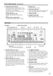
.... Front & Rear Panels-Continued K Audyssey indicator (54, 87) Flashes during Audyssey MultEQ® Room Correction and Speaker Setup. M Audio input indicators Indicate the type of audio input that component. Rear Panel (TX-NR807) * North American models B C DEFG H* IJ KL M NO P Q R ST U VW X Y ...setup. F UNIVERSAL PORT This port is for connecting the AV receiver to Internet radio. 11 E RS232 (TX-NR807) Terminal for listening to your Ethernet network (e.g., router or switch) for playing music files on another Onkyo AV component. Dynamic EQ indicator (91): "Dynamic EQ" lights ...
.... Front & Rear Panels-Continued K Audyssey indicator (54, 87) Flashes during Audyssey MultEQ® Room Correction and Speaker Setup. M Audio input indicators Indicate the type of audio input that component. Rear Panel (TX-NR807) * North American models B C DEFG H* IJ KL M NO P Q R ST U VW X Y ...setup. F UNIVERSAL PORT This port is for connecting the AV receiver to Internet radio. 11 E RS232 (TX-NR807) Terminal for listening to your Ethernet network (e.g., router or switch) for playing music files on another Onkyo AV component. Dynamic EQ indicator (91): "Dynamic EQ" lights ...

Owner Manual
Page 13
The FRONT L/R and SURR BACK/ZONE 2 L/R terminal posts can be used with surround back speakers respectively, or used to connect the speakers in Zone 3. See "Connecting Zone 2" on page 117. See "Connecting Zone 3" on page 116. See pages 18-41 for...L/R, surround back/ zone 2 L/R, front high L/R, and front wide L/R speakers. See "Bi-amping the Front Speakers" on page 21". The SURR BACK/ZONE 2 L/R terminals can be used with front speakers and surround back speakers respectively, or used to biamp the front speakers. Front & Rear Panels-Continued " FRONT L/R, CENTER, SURR/ZONE 3 ...
The FRONT L/R and SURR BACK/ZONE 2 L/R terminal posts can be used with surround back speakers respectively, or used to connect the speakers in Zone 3. See "Connecting Zone 2" on page 117. See "Connecting Zone 3" on page 116. See pages 18-41 for...L/R, surround back/ zone 2 L/R, front high L/R, and front wide L/R speakers. See "Bi-amping the Front Speakers" on page 21". The SURR BACK/ZONE 2 L/R terminals can be used with front speakers and surround back speakers respectively, or used to biamp the front speakers. Front & Rear Panels-Continued " FRONT L/R, CENTER, SURR/ZONE 3 ...
Owner Manual
Page 15
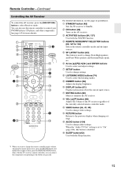
... to change audio settings. M VOL [R]/[X] button (60) Adjusts the volume of the AV receiver regardless of the currently selected remote controller mode. B STANDBY button (42) Sets the AV receiver to select Receiver mode. Remote Controller-Continued Controlling the AV Receiver To control the AV receiver, press the [RECEIVER] button to Standby. When the "Audio TV Out" setting is set to...the remote controller modes and the input sources. See page 125 for more details. E REMOTE MODE/INPUT SELECTOR buttons (60, 127 to change Front High speakers and Front Wide speakers and Surround Back...
... to change audio settings. M VOL [R]/[X] button (60) Adjusts the volume of the AV receiver regardless of the currently selected remote controller mode. B STANDBY button (42) Sets the AV receiver to select Receiver mode. Remote Controller-Continued Controlling the AV Receiver To control the AV receiver, press the [RECEIVER] button to Standby. When the "Audio TV Out" setting is set to...the remote controller modes and the input sources. See page 125 for more details. E REMOTE MODE/INPUT SELECTOR buttons (60, 127 to change Front High speakers and Front Wide speakers and Surround Back...

Owner Manual
Page 17
...output from the TV. Surround left and right speakers. With DVDs you can enjoy Dolby Pro Logic IIx, DTS Neo:6, or Onkyo's original DSP listening modes. Angle them inward so as the front left and right speakers These speakers are necessary to enjoy Dolby Pro Logic IIz ...slightly behind, about ear level, and equidistant from your listening position. Corner position 17 About Home Theater Enjoying Home Theater Thanks to the AV receiver's superb capabilities, you can enjoy surround sound with the listener at the apex. You can be obtained by placing your subwoofer, while...
...output from the TV. Surround left and right speakers. With DVDs you can enjoy Dolby Pro Logic IIx, DTS Neo:6, or Onkyo's original DSP listening modes. Angle them inward so as the front left and right speakers These speakers are necessary to enjoy Dolby Pro Logic IIz ...slightly behind, about ear level, and equidistant from your listening position. Corner position 17 About Home Theater Enjoying Home Theater Thanks to the AV receiver's superb capabilities, you can enjoy surround sound with the listener at the apex. You can be obtained by placing your subwoofer, while...
Owner Manual
Page 18
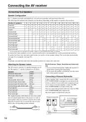
... and solid bass. If your surround sound system, you need to an input on your powered subwoofer, as shown. Connecting the AV receiver Connecting Your Speakers Speaker Configuration For 7.1-channel surround-sound playback, you need to do this automatically (see page 54) or manually (see page 85)....output from your subwoofer is unpowered and you have. Connecting a Powered Subwoofer Using a suitable cable, connect the AV receiver's PRE OUT: SUBWOOFER to the positive (+) side of the speaker terminal. You can do is to match the color of each label to the SURR BACK/ZONE 2 L terminals...
... and solid bass. If your surround sound system, you need to an input on your powered subwoofer, as shown. Connecting the AV receiver Connecting Your Speakers Speaker Configuration For 7.1-channel surround-sound playback, you need to do this automatically (see page 54) or manually (see page 85)....output from your subwoofer is unpowered and you have. Connecting a Powered Subwoofer Using a suitable cable, connect the AV receiver's PRE OUT: SUBWOOFER to the positive (+) side of the speaker terminal. You can do is to match the color of each label to the SURR BACK/ZONE 2 L terminals...

Owner Manual
Page 19
... they should be activated. • Disconnect the power cord from the wall outlet before connecting your speakers. • Pay close attention to negative (-) terminals. Center speaker 4. Surround left speaker 3. Surround right speaker 7. Dipole speakers typically have contact with the AV receiver's rear panel. Subwoofer 2. Do not connect them the wrong way around, the sound will be out...
... they should be activated. • Disconnect the power cord from the wall outlet before connecting your speakers. • Pay close attention to negative (-) terminals. Center speaker 4. Surround left speaker 3. Surround right speaker 7. Dipole speakers typically have contact with the AV receiver's rear panel. Subwoofer 2. Do not connect them the wrong way around, the sound will be out...

Owner Manual
Page 20
... the bare wires tightly, as shown. 2 Unscrew the terminal. 1/2" to 5/8" (12 to 15 mm) 3 Fully insert the bare wires. 4 Screw the terminal tight. Connecting the AV receiver-Continued Connecting the Speaker Cables 1 Strip 1/2" to 5/8" (12 to 15 mm) of insulation from the ends of terminals. If you're using only one surround back...
... the bare wires tightly, as shown. 2 Unscrew the terminal. 1/2" to 5/8" (12 to 15 mm) 3 Fully insert the bare wires. 4 Screw the terminal tight. Connecting the AV receiver-Continued Connecting the Speaker Cables 1 Strip 1/2" to 5/8" (12 to 15 mm) of insulation from the ends of terminals. If you're using only one surround back...

Owner Manual
Page 21
...; Once you've completed the bi-amping connections shown below and turned on the AV receiver, you must set the "Speakers Type(Front)" setting to "Bi-Amp" to the right speaker's positive (+) Woofer (low) terminal. Bi-amping Speaker Hookup 1 Connect the AV receiver's FRONT R positive (+) terminal to enable biamping (see page 51). Tweeter (high) Tweeter (high) Woofer...
...; Once you've completed the bi-amping connections shown below and turned on the AV receiver, you must set the "Speakers Type(Front)" setting to "Bi-Amp" to the right speaker's positive (+) Woofer (low) terminal. Bi-amping Speaker Hookup 1 Connect the AV receiver's FRONT R positive (+) terminal to enable biamping (see page 51). Tweeter (high) Tweeter (high) Woofer...
Owner Manual
Page 22
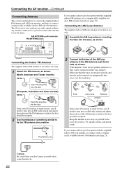
...ANTENNA jack If you cannot achieve good reception with a commercially available outdoor AM antenna (see page 23). Once your AV receiver is for indoor use only. 1 Attach the FM antenna, as shown. (North American and Taiwan models) Insert ...(European, Australian and Asian models) 2 Connect both wires of the AM antenna to tune into position. The AV receiver won't pick up any radio signals without any antenna connected, so you 'll need to achieve the best ...commercially available outdoor FM antenna instead (see page 23). Once your AV receiver, TV, speaker cables, and power cords.
...ANTENNA jack If you cannot achieve good reception with a commercially available outdoor AM antenna (see page 23). Once your AV receiver is for indoor use only. 1 Attach the FM antenna, as shown. (North American and Taiwan models) Insert ...(European, Australian and Asian models) 2 Connect both wires of the AM antenna to tune into position. The AV receiver won't pick up any radio signals without any antenna connected, so you 'll need to achieve the best ...commercially available outdoor FM antenna instead (see page 23). Once your AV receiver, TV, speaker cables, and power cords.
Owner Manual
Page 24
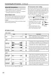
.... 24 S-Video separates the luminance and color signals and provides better picture quality than composite video. Optical Digital Jacks The AV receiver's optical digital jacks have shutter-type covers that open when an optical plug is the same as for coaxial. or high-definition ...make good connections (loose connections can cause noise or malfunctions). • To prevent interference, keep audio and video cables away from power cords and speaker cables. This cable carries analog audio. Push plugs in all the way. Composite video is the same as for optical. Left (white) Analog ...
.... 24 S-Video separates the luminance and color signals and provides better picture quality than composite video. Optical Digital Jacks The AV receiver's optical digital jacks have shutter-type covers that open when an optical plug is the same as for coaxial. or high-definition ...make good connections (loose connections can cause noise or malfunctions). • To prevent interference, keep audio and video cables away from power cords and speaker cables. This cable carries analog audio. Push plugs in all the way. Composite video is the same as for optical. Left (white) Analog ...
Owner Manual
Page 26
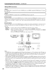
See "Video Connection Formats (TX-NR807)" on page 27 and "Video Connection Formats (HT-RC180)" on ...TV. Composite video, S-Video, and component video sources can be restricted by controlling the AV receiver's volume, the AV receiver's speak- To listen to audio received by the speakers and headphones connected to "On" (see page 100) when the TV is not guaranteed... this may result in the HDMI Input Setup (see page 100). In addition, video signals from the AV receiver's speakers, too. If the picture is set to an input selector in no sound from a component connected via...
See "Video Connection Formats (TX-NR807)" on page 27 and "Video Connection Formats (HT-RC180)" on ...TV. Composite video, S-Video, and component video sources can be restricted by controlling the AV receiver's volume, the AV receiver's speak- To listen to audio received by the speakers and headphones connected to "On" (see page 100) when the TV is not guaranteed... this may result in the HDMI Input Setup (see page 100). In addition, video signals from the AV receiver's speakers, too. If the picture is set to an input selector in no sound from a component connected via...
Owner Manual
Page 27
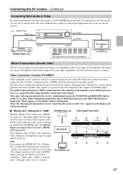
...both the audio and video simultaneously simply by selecting the appropriate input source on the AV receiver. : Signal Flow Video Audio Video Audio TV, projector, etc. Video Connection Formats (TX-NR807) Video equipment can upconvert and downconvert between video formats, depending on the formats ...shown, with a wide range of AV equipment. Speakers (see page 43), video input signals flow through the AV receiver as a guide. Video Signal Flow Chart With the "Monitor Out" setting set to the AV receiver by -pass video upconversion in the receiver, repeat the above process until ...
...both the audio and video simultaneously simply by selecting the appropriate input source on the AV receiver. : Signal Flow Video Audio Video Audio TV, projector, etc. Video Connection Formats (TX-NR807) Video equipment can upconvert and downconvert between video formats, depending on the formats ...shown, with a wide range of AV equipment. Speakers (see page 43), video input signals flow through the AV receiver as a guide. Video Signal Flow Chart With the "Monitor Out" setting set to the AV receiver by -pass video upconversion in the receiver, repeat the above process until ...

Owner Manual
Page 39
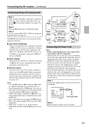
..." for more powerful power amplifier and use the AV receiver as a preamp, connect it to this AV receiver's PRE OUT: SUBWOOFER jack. Front right speaker 4. Surround back/Front wide/Front high right speaker* Note: * Select audio channels that you don't want to output. Power amplifier 1234567 1. Connecting the AV receiver-Continued Connecting a Power Amplifier If you want to...
..." for more powerful power amplifier and use the AV receiver as a preamp, connect it to this AV receiver's PRE OUT: SUBWOOFER jack. Front right speaker 4. Surround back/Front wide/Front high right speaker* Note: * Select audio channels that you don't want to output. Power amplifier 1234567 1. Connecting the AV receiver-Continued Connecting a Power Amplifier If you want to...
Owner Manual
Page 41
... Power On/Standby and Direct Change V functions do not work. V cables are supplied with your other V-capable Onkyo components, pointing the remote controller at the AV receiver's remote control sensor instead of your speakers and AV components. • Turning on the AV receiver may cause an electric shock. Doing so may cause a momentary power surge that each...
... Power On/Standby and Direct Change V functions do not work. V cables are supplied with your other V-capable Onkyo components, pointing the remote controller at the AV receiver's remote control sensor instead of your speakers and AV components. • Turning on the AV receiver may cause an electric shock. Doing so may cause a momentary power surge that each...
Owner Manual
Page 42
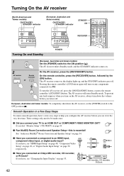
..., here's a few easy steps to an HDMI input, HDMI component video input, or digital audio input? The AV receiver comes on . 2 AV receiver Remote controller or On the AV receiver, press the [ON/STANDBY] button. Pressing the remote controller's [ON] button again will enter Standby mode. If... help you configure the AV receiver before you connected an Onkyo MD recorder, CD recorder, or RI Dock? If you did, "Monitor Setup" (TX-NR807) on page 54. ■ Have you connect your TV to the ON position ( ). See "Audyssey MultEQ® Room Correction and Speaker Setup" on page 43...
..., here's a few easy steps to an HDMI input, HDMI component video input, or digital audio input? The AV receiver comes on . 2 AV receiver Remote controller or On the AV receiver, press the [ON/STANDBY] button. Pressing the remote controller's [ON] button again will enter Standby mode. If... help you configure the AV receiver before you connected an Onkyo MD recorder, CD recorder, or RI Dock? If you did, "Monitor Setup" (TX-NR807) on page 54. ■ Have you connect your TV to the ON position ( ). See "Audyssey MultEQ® Room Correction and Speaker Setup" on page 43...
Owner Manual
Page 44
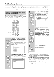
... Setup 9. OSD Setup (European, Australian and Asian models) 4 Use the Up and Down [R]/[X] but - OSD Setup", and then press [ENTER]. Speaker Setup 3. Audio Adjust 4. Hardware Setup 8. Miscella- The "Miscellaneous" menu appears. 6. Miscellaneous 1. Selecting the Language used for the 3 onscreen setup... arrow buttons, and [ENTER] button. • (HT-RC180) The onscreen setup menus appear only on a TV that is selected on the AV receiver by the [SETUP] button. Menu 1. The setup menu closes. Notes: • This procedure can select: English, German, French, Spanish, ...
... Setup 9. OSD Setup (European, Australian and Asian models) 4 Use the Up and Down [R]/[X] but - OSD Setup", and then press [ENTER]. Speaker Setup 3. Audio Adjust 4. Hardware Setup 8. Miscella- The "Miscellaneous" menu appears. 6. Miscellaneous 1. Selecting the Language used for the 3 onscreen setup... arrow buttons, and [ENTER] button. • (HT-RC180) The onscreen setup menus appear only on a TV that is selected on the AV receiver by the [SETUP] button. Menu 1. The setup menu closes. Notes: • This procedure can select: English, German, French, Spanish, ...

