
Owner Manual
Page 1
Artistry in Sound ONKYQ Audio Video Control Receiver TX-DS838 Instruction Manual = = 00 o 0 *O 1 I I I 1 I I OOO All models except European models c= 0 0 0O CO 0 0) I I I I I 000 European models CONTENTS Features 2 Important safeguards 3 Precautions 4 ...Introduction 11 Connecting audio equipment 12 Connecting video equipment 13 Positioning speakers 15 Connecting speakers 16 Connecting optional amplifiers 17 Connecting the power 17 Connecting antennas 18 Setting up the Multi-Room Remote System 20 Multi-Room Remote Control .22 Using the on-screen display...
Artistry in Sound ONKYQ Audio Video Control Receiver TX-DS838 Instruction Manual = = 00 o 0 *O 1 I I I 1 I I OOO All models except European models c= 0 0 0O CO 0 0) I I I I I 000 European models CONTENTS Features 2 Important safeguards 3 Precautions 4 ...Introduction 11 Connecting audio equipment 12 Connecting video equipment 13 Positioning speakers 15 Connecting speakers 16 Connecting optional amplifiers 17 Connecting the power 17 Connecting antennas 18 Setting up the Multi-Room Remote System 20 Multi-Room Remote Control .22 Using the on-screen display...
Owner Manual
Page 2
...in compliance with the corresponding technical standards such as practical . These limits are compatible with the limits for purchasing the Onkyo TX-DS838 Audio Video Control Receiver. CAUTION: TO PREVENT ELECTRIC SHOCK, MATCH WIDE BLADE OF PLUG TO WIDE SLOT, FULLY INSERT...; 4 Gold-plated audio inputs and 4 gold-plated composite video inputs ■ 3 Digital inputs (AC-3 RF/optical/coaxial) ■ Intelligent Power Management (IPM) turns ON/OFF entire A/V system with the instructions, may cause harmful interference to radio communications. and Canadian models are designed to ...
...in compliance with the corresponding technical standards such as practical . These limits are compatible with the limits for purchasing the Onkyo TX-DS838 Audio Video Control Receiver. CAUTION: TO PREVENT ELECTRIC SHOCK, MATCH WIDE BLADE OF PLUG TO WIDE SLOT, FULLY INSERT...; 4 Gold-plated audio inputs and 4 gold-plated composite video inputs ■ 3 Digital inputs (AC-3 RF/optical/coaxial) ■ Intelligent Power Management (IPM) turns ON/OFF entire A/V system with the instructions, may cause harmful interference to radio communications. and Canadian models are designed to ...
Owner Manual
Page 3
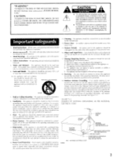
...'s enclosure that may block the ventilation openings; Heat - Polarization - If there is a safety feature. Damage Requiring Service - The power-supply cord or the plug has been damaged; NATIONAL ELECTRICAL CODE S2898A ANTENNA DISCHARGE UNIT (NEC SECTION 810-20) GROUNDING CONDUCTORS (NEC... to the receiver, be adhered to rain: or D. Under no circumstances should be serviced by the manufacturer. 6A. Power-Cord Protection - Power-supply cords should be free space of the antennadischarge unit, connection to operate normally or exhibits a marked change in a...
...'s enclosure that may block the ventilation openings; Heat - Polarization - If there is a safety feature. Damage Requiring Service - The power-supply cord or the plug has been damaged; NATIONAL ELECTRICAL CODE S2898A ANTENNA DISCHARGE UNIT (NEC SECTION 810-20) GROUNDING CONDUCTORS (NEC... to the receiver, be adhered to rain: or D. Under no circumstances should be serviced by the manufacturer. 6A. Power-Cord Protection - Power-supply cords should be free space of the antennadischarge unit, connection to operate normally or exhibits a marked change in a...
Owner Manual
Page 4
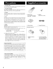
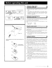
... You can only be plugged in your area before turning the power button on , contact your Onkyo authorized service station. 4. AC fuse The fuse is located inside the chassis and is exposed to conform with a voltage selector to a highly humid climate. Power WARNING BEFORE PLUGGING IN THE UNIT FOR THE FIRST TIME, READ...
... You can only be plugged in your area before turning the power button on , contact your Onkyo authorized service station. 4. AC fuse The fuse is located inside the chassis and is exposed to conform with a voltage selector to a highly humid climate. Power WARNING BEFORE PLUGGING IN THE UNIT FOR THE FIRST TIME, READ...
Owner Manual
Page 5
... indicated by the diagram inside the battery compartment, then close the cover. • When the batteries lose their power, the indicator on the remote control will help you get optimal use . • The TX-DS838 comes equipped with a switch that long-life AA (LR6 or AM-3) size alkaline batteries be used when replacing...
... indicated by the diagram inside the battery compartment, then close the cover. • When the batteries lose their power, the indicator on the remote control will help you get optimal use . • The TX-DS838 comes equipped with a switch that long-life AA (LR6 or AM-3) size alkaline batteries be used when replacing...
Owner Manual
Page 7
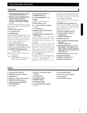
... remote control to +20 dB. Control positions and names Front panel ® MR OFF (Multi-Room Remote System on/off) button and indicator [22] (1) POWER switch and POWER indicator (SYSTEM switch and SYSTEM indicator on the European models) and STAND-BY/RECEIVED indicator [17, 29] The STAND-BY/RECEIVED indicator lights up...
... remote control to +20 dB. Control positions and names Front panel ® MR OFF (Multi-Room Remote System on/off) button and indicator [22] (1) POWER switch and POWER indicator (SYSTEM switch and SYSTEM indicator on the European models) and STAND-BY/RECEIVED indicator [17, 29] The STAND-BY/RECEIVED indicator lights up...
Owner Manual
Page 8
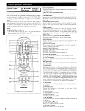
... code is displayed. The remote control can be used to operate components equipped with an Onkyo RI (Remote Interactive) connector and connected to the RI connectors on the remote control is pressed. ® POWER button Switches the TX-DS838 between the speakers during the volume adjustment of this button is pressed while the remaining...
... code is displayed. The remote control can be used to operate components equipped with an Onkyo RI (Remote Interactive) connector and connected to the RI connectors on the remote control is pressed. ® POWER button Switches the TX-DS838 between the speakers during the volume adjustment of this button is pressed while the remaining...
Owner Manual
Page 9
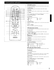
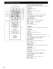
... select a group (A, B, C or D) for discs in the CD changer. © T button Allows you to use the number keys to specify a track on and off the power. ® SET button Allows you to start programming the video device codes of other brands in order to operate them using this remote control. ©...
... select a group (A, B, C or D) for discs in the CD changer. © T button Allows you to use the number keys to specify a track on and off the power. ® SET button Allows you to start programming the video device codes of other brands in order to operate them using this remote control. ©...
Owner Manual
Page 10
.... CABLE controls: The following buttons can be used when the device select switch 4 is set to CABLE. © PWR button Turns on and off the power. © SET button Refer to the explanation for this button under VDP controls. © Enter button Refer to recall a previously selected channel. 0 CH +/-...controls: The following buttons can be used when the device select switch • is set to TV. © PWR button Turns on and off the power. © T button Toggles between the VCR and TV screens. C) SET button Refer to the explanation for this button under VDP controls. " Fast ...
.... CABLE controls: The following buttons can be used when the device select switch 4 is set to CABLE. © PWR button Turns on and off the power. © SET button Refer to the explanation for this button under VDP controls. © Enter button Refer to recall a previously selected channel. 0 CH +/-...controls: The following buttons can be used when the device select switch • is set to TV. © PWR button Turns on and off the power. © T button Toggles between the VCR and TV screens. C) SET button Refer to the explanation for this button under VDP controls. " Fast ...
Owner Manual
Page 12
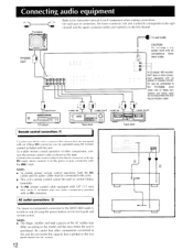
...I I 1 I I = ooe ee Tape deck Remote control connections Cassette tape decks and a compact disc player that are being used to the TX-DS838. AC outlet connections [1] The power to components connected to the SWITCHED outlet is printed on the front panel and remote control. C O A CD player, MD recorder, DAT deck ...the RI cables and the audio cables must be connected to the units. • This unit's remote control cannot be connected to control Onkyo turntables. • An RI remote control cable equipped with 1/8" (3.5 mm) mini jacks is purchased. Be careful that is turned on ...
...I I 1 I I = ooe ee Tape deck Remote control connections Cassette tape decks and a compact disc player that are being used to the TX-DS838. AC outlet connections [1] The power to components connected to the SWITCHED outlet is printed on the front panel and remote control. C O A CD player, MD recorder, DAT deck ...the RI cables and the audio cables must be connected to the units. • This unit's remote control cannot be connected to control Onkyo turntables. • An RI remote control cable equipped with 1/8" (3.5 mm) mini jacks is purchased. Be careful that is turned on ...
Owner Manual
Page 14
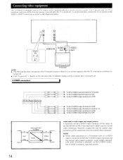
...an IPM system, which automatically turns on the receiver's power 3 to 5 seconds after the TV is turned on, and turns off the receiver's power 5 seconds after the TV is turned on the left side of a VCR S Input Video Video signal flow TX-DS838 S Priority Output Video Video and S-VIDEO input and output... later it is turned off. • If the TV goes off, "•" flashes on or before it also turns off . Connecting video equipment The TX-DS838 is equipped with an S-VIDEO input is connected to the VIDEO-3 INPUT connectors as shown in the illustration below. 0 0 VIDEO-3 IPM ON OFF (TV...
...an IPM system, which automatically turns on the receiver's power 3 to 5 seconds after the TV is turned on, and turns off the receiver's power 5 seconds after the TV is turned on the left side of a VCR S Input Video Video signal flow TX-DS838 S Priority Output Video Video and S-VIDEO input and output... later it is turned off. • If the TV goes off, "•" flashes on or before it also turns off . Connecting video equipment The TX-DS838 is equipped with an S-VIDEO input is connected to the VIDEO-3 INPUT connectors as shown in the illustration below. 0 0 VIDEO-3 IPM ON OFF (TV...

Owner Manual
Page 15
...to the connected speakers in order to the speaker instruction manual for more details. Subwoofer: Install a subwoofer with the room layout in power amplifier for standard speaker placement. Standard speaker placement For ideal Surround effects, all speakers should face the seated listener and be installed. ...right and center speakers should be placed at ear level. The placement of the subwoofer does not affect the final quality of a layout for powerful bass sounds. I I TV or Screen Sub- The illustration below shows an example of the sound image too much, so you can ...
...to the connected speakers in order to the speaker instruction manual for more details. Subwoofer: Install a subwoofer with the room layout in power amplifier for standard speaker placement. Standard speaker placement For ideal Surround effects, all speakers should face the seated listener and be installed. ...right and center speakers should be placed at ear level. The placement of the subwoofer does not affect the final quality of a layout for powerful bass sounds. I I TV or Screen Sub- The illustration below shows an example of the sound image too much, so you can ...
Owner Manual
Page 17
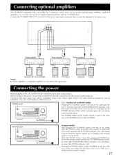
.... (When the SYSTEM switch is set to ON, pressing the POWER button on the TX-DS838. Subwoofer Center III ' I 0©00* U.S., Canadian and worldwide models: Plugging the TX-DS838's power cord into an AC outlet, press the SYSTEM switch to put the unit in power-on the power, be operated and its SYSTEM indicator is lit). Turning on...
.... (When the SYSTEM switch is set to ON, pressing the POWER button on the TX-DS838. Subwoofer Center III ' I 0©00* U.S., Canadian and worldwide models: Plugging the TX-DS838's power cord into an AC outlet, press the SYSTEM switch to put the unit in power-on the power, be operated and its SYSTEM indicator is lit). Turning on...

Owner Manual
Page 19
..., etc. The AM loop antenna is positioned as follows: • Keep the antenna away from his unit, the TV, speaker cables and power cords. Extend the antenna and move it where the clearest sound is received. Position it until the clearest signal is received. Put it in the T-...
..., etc. The AM loop antenna is positioned as follows: • Keep the antenna away from his unit, the TV, speaker cables and power cords. Extend the antenna and move it where the clearest sound is received. Position it until the clearest signal is received. Put it in the T-...
Owner Manual
Page 20
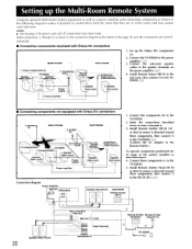
Connecting block Remote control SUB ROOM _5. Connect the components (b) to the speaker terminals on the power amplifier. (I)) 4. Onkyo components (a) Speaker (Main room) TX-DS838 Speaker (Main room) 4. Install Remote Emitter Head HE-10 so that its sensor is directed toward these components, then connect it to the TXDS838. NOTE: &#...
Connecting block Remote control SUB ROOM _5. Connect the components (b) to the speaker terminals on the power amplifier. (I)) 4. Onkyo components (a) Speaker (Main room) TX-DS838 Speaker (Main room) 4. Install Remote Emitter Head HE-10 so that its sensor is directed toward these components, then connect it to the TXDS838. NOTE: &#...
Owner Manual
Page 21
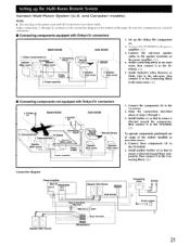
... 3. Speaker \ Sub room) 1. Connect the sub-room speaker cables to the TXDS838. 5. Emitter (c) MAIN ROOM 5. Onkyo components (a) Speaker (Main room) TX-DS838 Speaker (Main room) \ 4. Connecting block N \H_ Power supply 2. Install Connecting Block in the main room, then connect it to the TX-DS838. 5. Connect these components, then connect it to the speaker terminals on the...
... 3. Speaker \ Sub room) 1. Connect the sub-room speaker cables to the TXDS838. 5. Emitter (c) MAIN ROOM 5. Onkyo components (a) Speaker (Main room) TX-DS838 Speaker (Main room) \ 4. Connecting block N \H_ Power supply 2. Install Connecting Block in the main room, then connect it to the TX-DS838. 5. Connect these components, then connect it to the speaker terminals on the...

Owner Manual
Page 29
... T-2 MONITOR indicator is not lit when a source other component is being selected. Refer to pages 42 to turn on the power. Press either the POWER button on the remote control or the POWER switch (SYSTEM on the European models) on the main unit to 45 for more details on using the tuner. 6. Refer...
... T-2 MONITOR indicator is not lit when a source other component is being selected. Refer to pages 42 to turn on the power. Press either the POWER button on the remote control or the POWER switch (SYSTEM on the European models) on the main unit to 45 for more details on using the tuner. 6. Refer...

Owner Manual
Page 47
...8226; Insert batteries. Hum or low-frequency noise • Poor or no input ground • Poor or no power • The amplifier protection circuitry has been • Contact your Onkyo service center. to each other components, e.g. AM stations cannot be less compared to the sound level when the DOLBY...waves due to the sensor Front panel controls function but no batteries in the computer circuits of the TX-DS838. • The AC fuse is blown. • Connect the power cord. • Turn the power off . • The noise is caused by turning a fluorescent lamp on and off and then ...
...8226; Insert batteries. Hum or low-frequency noise • Poor or no input ground • Poor or no power • The amplifier protection circuitry has been • Contact your Onkyo service center. to each other components, e.g. AM stations cannot be less compared to the sound level when the DOLBY...waves due to the sensor Front panel controls function but no batteries in the computer circuits of the TX-DS838. • The AC fuse is blown. • Connect the power cord. • Turn the power off . • The noise is caused by turning a fluorescent lamp on and off and then ...
Owner Manual
Page 48
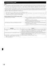
...weak, replace them. • Press the appropriate INPUT SELECTOR button on the back of the TX-DS838 to the proper value for the coun- Some or all buttons on the video component don... start operating it. • Depending on the TXDS838. A : On the back of your authorized Onkyo service center. This device employs a microcomputer to reset the unit. 1. Problem with the video component.... controller may not work. Troubleshooting guide NOTE: • The tuning steps by an external power supply, radio waves, or other electrical source results in an accident which the tuned frequency ...
...weak, replace them. • Press the appropriate INPUT SELECTOR button on the back of the TX-DS838 to the proper value for the coun- Some or all buttons on the video component don... start operating it. • Depending on the TXDS838. A : On the back of your authorized Onkyo service center. This device employs a microcomputer to reset the unit. 1. Problem with the video component.... controller may not work. Troubleshooting guide NOTE: • The tuning steps by an external power supply, radio waves, or other electrical source results in an accident which the tuned frequency ...

Owner Manual
Page 49
...and 20,000 Hz with no more than 0.08% total harmonic distortion. Specifications AMPLIFIER SECTION Power output: Stereo model (Surround mode: OFF) L and R FRONT SPEAKERS 100 watts per channel min. Continuous power 2 x 150 Watt at 6 ohms (DIN) Surround mode L and R FRONT and ...and R SURROUND SPEAKERS 50 watts per channel min. nels driven between 100 and 10,000 Hz 17.2 dBf AM: Tuning: U.S. IM distortion: 0.08% at rated power (L and R) Damping factor: 60 at 8 ohms (L and R) Input sensitivity/impedance: Phono: 2.5 mV/50 kohms Line (CD, TAPE-1 and - 2,VIDEO-1 ...
...and 20,000 Hz with no more than 0.08% total harmonic distortion. Specifications AMPLIFIER SECTION Power output: Stereo model (Surround mode: OFF) L and R FRONT SPEAKERS 100 watts per channel min. Continuous power 2 x 150 Watt at 6 ohms (DIN) Surround mode L and R FRONT and ...and R SURROUND SPEAKERS 50 watts per channel min. nels driven between 100 and 10,000 Hz 17.2 dBf AM: Tuning: U.S. IM distortion: 0.08% at rated power (L and R) Damping factor: 60 at 8 ohms (L and R) Input sensitivity/impedance: Phono: 2.5 mV/50 kohms Line (CD, TAPE-1 and - 2,VIDEO-1 ...


