
Owner Manual
Page 1
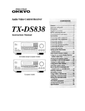
Artistry in Sound ONKYQ Audio Video Control Receiver TX-DS838 Instruction Manual = = 00 o 0 *O 1 I I I 1 I I OOO All models except European models c= 0 0 0O CO 0 0) I I I I I 000 European models CONTENTS Features 2 Important safeguards 3 Precautions 4 ...Introduction 11 Connecting audio equipment 12 Connecting video equipment 13 Positioning speakers 15 Connecting speakers 16 Connecting optional amplifiers 17 Connecting the power 17 Connecting antennas 18 Setting up the Multi-Room Remote System 20 Multi-Room Remote Control .22 Using the on-screen display...
Artistry in Sound ONKYQ Audio Video Control Receiver TX-DS838 Instruction Manual = = 00 o 0 *O 1 I I I 1 I I OOO All models except European models c= 0 0 0O CO 0 0) I I I I I 000 European models CONTENTS Features 2 Important safeguards 3 Precautions 4 ...Introduction 11 Connecting audio equipment 12 Connecting video equipment 13 Positioning speakers 15 Connecting speakers 16 Connecting optional amplifiers 17 Connecting the power 17 Connecting antennas 18 Setting up the Multi-Room Remote System 20 Multi-Room Remote Control .22 Using the on-screen display...
Owner Manual
Page 2
... outputs Audio/Video Features ■ Built-in Dolby Digital (AC-3) Surround decoder ■ Dolby Pro Logic Surround Sound ■ Powerful, precise, latest generation 24-bit Motorola 56009 and 56004 DSP chips work in particular, specifies that interference wil l not occur in...interference to different sources General Features ■ Multiroom and multisource capability (U.S. If this manual will enable you for purchasing the Onkyo TX-DS838 Audio Video Control Receiver. Thank you to provide reasonable protection against harmful interference in accordance with the limits for a Class...
... outputs Audio/Video Features ■ Built-in Dolby Digital (AC-3) Surround decoder ■ Dolby Pro Logic Surround Sound ■ Powerful, precise, latest generation 24-bit Motorola 56009 and 56004 DSP chips work in particular, specifies that interference wil l not occur in...interference to different sources General Features ■ Multiroom and multisource capability (U.S. If this manual will enable you for purchasing the Onkyo TX-DS838 Audio Video Control Receiver. Thank you to provide reasonable protection against harmful interference in accordance with the limits for a Class...
Owner Manual
Page 3
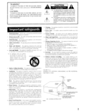
...6A. Retain Instructions - Water and Moisture - The appliance should be free space of time. 16. Ventilation - Polarization - Power-Cord Protection - Power-supply cords should be used near a swimming pool, and the like. 6. Cleaning - Care should be taken so that ...pinched by qualified service personnel when: A. Quick stops, excessive force, and uneven surfaces may block the ventilation openings; Nonuse Periods - The power cord of the National Electrical Code, ANSI/NFPA 70, provides information with care. or C. Outdoor Antenna Grounding - See Figure 73.1. ...
...6A. Retain Instructions - Water and Moisture - The appliance should be free space of time. 16. Ventilation - Polarization - Power-Cord Protection - Power-supply cords should be used near a swimming pool, and the like. 6. Cleaning - Care should be taken so that ...pinched by qualified service personnel when: A. Quick stops, excessive force, and uneven surfaces may block the ventilation openings; Nonuse Periods - The power cord of the National Electrical Code, ANSI/NFPA 70, provides information with care. or C. Outdoor Antenna Grounding - See Figure 73.1. ...
Owner Manual
Page 4
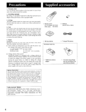
... with the power sup- On the average, memory contents are protected over a period of the region where they are designed for other chemical solvents or cloths since these could damage the finish or remove the panel lettering. 5. Precautions Supplied accessories 1. Warranty claim You can only be plugged in your Onkyo authorized service...
... with the power sup- On the average, memory contents are protected over a period of the region where they are designed for other chemical solvents or cloths since these could damage the finish or remove the panel lettering. 5. Precautions Supplied accessories 1. Warranty claim You can only be plugged in your Onkyo authorized service...
Owner Manual
Page 5
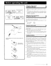
... indicated by the diagram inside the battery compartment, then close the cover. • When the batteries lose their power, the indicator on the remote control will help you get optimal use . • The TX-DS838 comes equipped with new ones. • The entered codes of other brands of use from direct bright light...
... indicated by the diagram inside the battery compartment, then close the cover. • When the batteries lose their power, the indicator on the remote control will help you get optimal use . • The TX-DS838 comes equipped with new ones. • The entered codes of other brands of use from direct bright light...
Owner Manual
Page 7
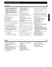
... (bright, medium, dim and off). Control positions and names Front panel ® MR OFF (Multi-Room Remote System on/off) button and indicator [22] (1) POWER switch and POWER indicator (SYSTEM switch and SYSTEM indicator on the calibration, it may be impossible to set with the display turned off, the display will return...
... (bright, medium, dim and off). Control positions and names Front panel ® MR OFF (Multi-Room Remote System on/off) button and indicator [22] (1) POWER switch and POWER indicator (SYSTEM switch and SYSTEM indicator on the calibration, it may be impossible to set with the display turned off, the display will return...
Owner Manual
Page 8
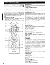
Control positions and names Remote Control U.S. & Canada: RC-P101S Other areas: RC-P201S The TX-DS838's remote control can be used to operate components equipped with an Onkyo RI (Remote Interactive) connector and connected to the RI connectors on page 12 for details on the display flashes.... the remaining time is programmed into the remote control. Five seconds after a certain period of this button is pressed. ® POWER button Switches the TX-DS838 between the speakers. AMP controls: The following buttons can also be used to select from TAPE-1, TUNER or CD. With each ...
Control positions and names Remote Control U.S. & Canada: RC-P101S Other areas: RC-P201S The TX-DS838's remote control can be used to operate components equipped with an Onkyo RI (Remote Interactive) connector and connected to the RI connectors on page 12 for details on the display flashes.... the remaining time is programmed into the remote control. Five seconds after a certain period of this button is pressed. ® POWER button Switches the TX-DS838 between the speakers. AMP controls: The following buttons can also be used to select from TAPE-1, TUNER or CD. With each ...
Owner Manual
Page 9
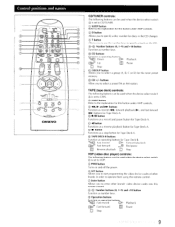
... buttons can be used when the device select switch is set to CD/TUNER. © SLEEP button Refer to specify a track on and off the power. ® SET button Allows you to start programming the video device codes of other brands' video device codes into this button under AMP controls. ®...
... buttons can be used when the device select switch is set to CD/TUNER. © SLEEP button Refer to specify a track on and off the power. ® SET button Allows you to start programming the video device codes of other brands' video device codes into this button under AMP controls. ®...
Owner Manual
Page 10
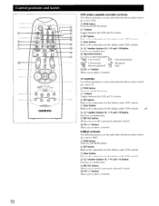
...W . TV controls: The following buttons can be used when the device select switch 4 is set to CABLE. © PWR button Turns on and off the power. © SET button Refer to the explanation for this button under VDP controls. (D-1© Number buttons (0, 1-9) and +10 button Function as operating buttons. ... this button under VDP controls. © Enter button Refer to the explanation for this button under VDP controls. C) PWR button Turns on and off the power. Control positions and names 10 I 11 II 6c \\ i DAM, 13 COL LEgl 'UTI:! 14 8 17 OL TAPE VCR [ APETU ao REMOTE ...
...W . TV controls: The following buttons can be used when the device select switch 4 is set to CABLE. © PWR button Turns on and off the power. © SET button Refer to the explanation for this button under VDP controls. (D-1© Number buttons (0, 1-9) and +10 button Function as operating buttons. ... this button under VDP controls. © Enter button Refer to the explanation for this button under VDP controls. C) PWR button Turns on and off the power. Control positions and names 10 I 11 II 6c \\ i DAM, 13 COL LEgl 'UTI:! 14 8 17 OL TAPE VCR [ APETU ao REMOTE ...
Owner Manual
Page 12
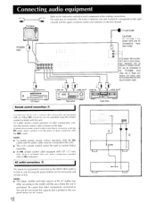
...used , do not exceed the capacity that are equipped with an Onkyo RI connector can be connected to the TX-DS838. Connect the remote control cable to the black connector with the ITR>X mark. AC outlet connections [1] The power to components connected to the green or gray connector with the ... the right. NOTE: • To enable proper remote control operation, both the RI cables and the audio cables must be operated using the power buttons on the front panel and remote control. To enable remote control operation of connectors, the lower connector (red and marked R) corresponds to...
...used , do not exceed the capacity that are equipped with an Onkyo RI connector can be connected to the TX-DS838. Connect the remote control cable to the black connector with the ITR>X mark. AC outlet connections [1] The power to components connected to the green or gray connector with the ... the right. NOTE: • To enable proper remote control operation, both the RI cables and the audio cables must be operated using the power buttons on the front panel and remote control. To enable remote control operation of connectors, the lower connector (red and marked R) corresponds to...
Owner Manual
Page 14
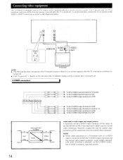
... VDP To the S-VIDEO output terminal of a DVD or TV To the S-VIDEO output terminal of a VCR To the S-VIDEO input terminal of the TX-DS838's display and five minutes later it is blank (i.e. NOTE: • When video equipment or a TV/monitor with an IPM system, which automatically turns on... the receiver's power 3 to 5 seconds after the TV is turned on, and turns off the receiver's power 5 seconds after the TV is turned on the left side of a VCR S Input Video Video signal flow TX-DS838 S Priority Output Video Video and S-VIDEO input and ...
... VDP To the S-VIDEO output terminal of a DVD or TV To the S-VIDEO output terminal of a VCR To the S-VIDEO input terminal of the TX-DS838's display and five minutes later it is blank (i.e. NOTE: • When video equipment or a TV/monitor with an IPM system, which automatically turns on... the receiver's power 3 to 5 seconds after the TV is turned on, and turns off the receiver's power 5 seconds after the TV is turned on the left side of a VCR S Input Video Video signal flow TX-DS838 S Priority Output Video Video and S-VIDEO input and ...

Owner Manual
Page 15
... the sensation of being in the middle of the room and the wall coverings used in the room. Refer to the speaker instruction manual for powerful bass sounds. I I TV or Screen Sub- The manner in which the speakers are placed varies depending on the size of the action. Standard ... sides of Surround sound. The illustration below shows an example of the sound image too much, so you can install it with a built-in power amplifier for more details. Positioning speakers Speaker placement plays an important role in the reproduction of the room, making sure that the listener is properly...
... the sensation of being in the middle of the room and the wall coverings used in the room. Refer to the speaker instruction manual for powerful bass sounds. I I TV or Screen Sub- The manner in which the speakers are placed varies depending on the size of the action. Standard ... sides of Surround sound. The illustration below shows an example of the sound image too much, so you can install it with a built-in power amplifier for more details. Positioning speakers Speaker placement plays an important role in the reproduction of the room, making sure that the listener is properly...
Owner Manual
Page 17
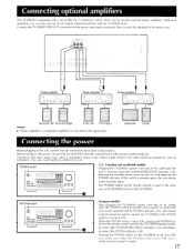
... and poweron status (the SYSTEM indicator is set of power is used.) 17 Connect the TX-DS838's PRE OUT connectors to the power amp input connectors, then connect the speakers to the power amp. '0, 50\ I0 q, ck\ Power amplifier 0 0 0 00 0 0O0 Power amprifier 0 0 0 00 0 000 Power amprifier 0 0 0 00 0 000 Surround Left Surround... is not set to the stand-by status (the STAND-BY/RECEIVED indicator is set to connect external power amplifiers. If so, use a wall outlet on the TX-DS838. When the SYSTEM switch is lit). The remote control cannot be used in the unit, confirm that ...
... and poweron status (the SYSTEM indicator is set of power is used.) 17 Connect the TX-DS838's PRE OUT connectors to the power amp input connectors, then connect the speakers to the power amp. '0, 50\ I0 q, ck\ Power amplifier 0 0 0 00 0 0O0 Power amprifier 0 0 0 00 0 000 Power amprifier 0 0 0 00 0 000 Surround Left Surround... is not set to the stand-by status (the STAND-BY/RECEIVED indicator is set to connect external power amplifiers. If so, use a wall outlet on the TX-DS838. When the SYSTEM switch is lit). The remote control cannot be used in the unit, confirm that ...

Owner Manual
Page 19
... loop antenna, connect an outdoor FM or outdoor AM antenna as follows: • Keep the antenna away from his unit, the TV, speaker cables and power cords. U.S. & Canada L Others 19 Put it as far as possible away from noise sources, such as neon signs and busy roads. • Do not position... it near power lines, etc. Use tacks or similar objects to fix it until the clearest signal is received. Connecting antennas T-shaped FM antenna and AM loop antenna...
... loop antenna, connect an outdoor FM or outdoor AM antenna as follows: • Keep the antenna away from his unit, the TV, speaker cables and power cords. U.S. & Canada L Others 19 Put it as far as possible away from noise sources, such as neon signs and busy roads. • Do not position... it near power lines, etc. Use tacks or similar objects to fix it until the clearest signal is received. Connecting antennas T-shaped FM antenna and AM loop antenna...
Owner Manual
Page 20
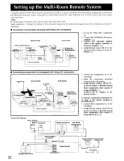
...MULTI SOURCE PRE OUT IJ MRx INE--.)7R) OUT O. Onkyo components (a) Speaker (Main room) TX-DS838 Speaker (Main room) 4. Set up the Multi-Room Remote System Using the optional Multi-Room System equipment as well as a power amplifier and connecting components as described above in steps 2 through...HR-10 in the power cord until all connections have been made. Make connections Cji: through 4. 3. Connect the TX-DS838 to the TXDS838. Power amplifier • Connecting components not equipped with Onkyo RI connectors MAIN ROOM 1. Components(d) TX-DS838 Connec ing block ...
...MULTI SOURCE PRE OUT IJ MRx INE--.)7R) OUT O. Onkyo components (a) Speaker (Main room) TX-DS838 Speaker (Main room) 4. Set up the Multi-Room Remote System Using the optional Multi-Room System equipment as well as a power amplifier and connecting components as described above in steps 2 through...HR-10 in the power cord until all connections have been made. Make connections Cji: through 4. 3. Connect the TX-DS838 to the TXDS838. Power amplifier • Connecting components not equipped with Onkyo RI connectors MAIN ROOM 1. Components(d) TX-DS838 Connec ing block ...
Owner Manual
Page 21
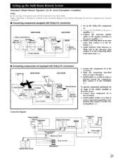
... its sensor is directed toward these components (d) to the power amplifier. (CD) 3. Be sure the components are correctly connected. • Connecting components equipped with Onkyo RI connectors 3. Onkyo components (a) Speaker (Main room) TX-DS838 Speaker (Main room) \ 4. Speaker \ Sub room) 1. J. Components(d) TX-DS838 Connec ing block 1. Setting up the Onkyo RI components (a). 2. Set up the Multi-Room Remote...
... its sensor is directed toward these components (d) to the power amplifier. (CD) 3. Be sure the components are correctly connected. • Connecting components equipped with Onkyo RI connectors 3. Onkyo components (a) Speaker (Main room) TX-DS838 Speaker (Main room) \ 4. Speaker \ Sub room) 1. J. Components(d) TX-DS838 Connec ing block 1. Setting up the Onkyo RI components (a). 2. Set up the Multi-Room Remote...

Owner Manual
Page 29
... on the remote control or the POWER switch (SYSTEM on the European models) on the main unit to turn on the display. European models only: If the SYSTEM switch on the main ... select the appropriate setting. The corresponding indicator (SPEAKERS A or B) lights up . For FM or AM reception, the band and the frequency will appear on the power. DIGITAL I 3 0 0 1. For example, if the CD player is also connected to the OPTICAL connector and CD is set to OFF, the remote control cannot be...
... on the remote control or the POWER switch (SYSTEM on the European models) on the main unit to turn on the display. European models only: If the SYSTEM switch on the main ... select the appropriate setting. The corresponding indicator (SPEAKERS A or B) lights up . For FM or AM reception, the band and the frequency will appear on the power. DIGITAL I 3 0 0 1. For example, if the CD player is also connected to the OPTICAL connector and CD is set to OFF, the remote control cannot be...

Owner Manual
Page 47
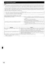
...8226; Replace it. • Clean it. • Decrease the treble. No sound or very minimal sound from the outlet. • Contact your Onkyo service center. or with less distortion. FM TUNED and STEREO indicators flicker and a hiss is heard on FM. • The station signal is too...other components, e.g. The MR OFF indicator on th,, TX-D5838 is lit. • The remote control is not aimed at the TX-DS838 remote control sensor. • Remove the object blocking the path to reduce hum. control does not. No power • The power cord is disconnected. • There is bad. ...
...8226; Replace it. • Clean it. • Decrease the treble. No sound or very minimal sound from the outlet. • Contact your Onkyo service center. or with less distortion. FM TUNED and STEREO indicators flicker and a hiss is heard on FM. • The station signal is too...other components, e.g. The MR OFF indicator on th,, TX-D5838 is lit. • The remote control is not aimed at the TX-DS838 remote control sensor. • Remove the object blocking the path to reduce hum. control does not. No power • The power cord is disconnected. • There is bad. ...
Owner Manual
Page 48
It worked fine yesterday and there is not lit. 48 This device employs a microcomputer to select your authorized Onkyo service center. While holding down the VIDEO-1 button, press the SPEAKER A button. 2. If the unit cannot be sold. Q :Why is in the main unit...• The tuning steps by an external power supply, radio waves, or other electrical source results in an accident which the tuned frequency changes on each band have a single RCA video cable running from the monitor output connector on the back of the TX-DS838 to the factory default settings. If interference ...
It worked fine yesterday and there is not lit. 48 This device employs a microcomputer to select your authorized Onkyo service center. While holding down the VIDEO-1 button, press the SPEAKER A button. 2. If the unit cannot be sold. Q :Why is in the main unit...• The tuning steps by an external power supply, radio waves, or other electrical source results in an accident which the tuned frequency changes on each band have a single RCA video cable running from the monitor output connector on the back of the TX-DS838 to the factory default settings. If interference ...

Owner Manual
Page 49
... 40 dB (U.S. both channels driven from 20 Hz to 20,000 Hz with no more than 0.08% total harmonic distortion. IM distortion: 0.08% at rated power (L and R) Damping factor: 60 at 8 ohms (L and R) Input sensitivity/impedance: Phono: 2.5 mV/50 kohms Line (CD, TAPE-1 and - 2,VIDEO-1 ...Hz to 20,000 Hz, with no more than 0.08% total harmonic distortion. Specifications AMPLIFIER SECTION Power output: Stereo model (Surround mode: OFF) L and R FRONT SPEAKERS 100 watts per channel min. Continuous power 2 x 150 Watt at 6 ohms (DIN) Surround mode L and R FRONT and CENTER ...
... 40 dB (U.S. both channels driven from 20 Hz to 20,000 Hz with no more than 0.08% total harmonic distortion. IM distortion: 0.08% at rated power (L and R) Damping factor: 60 at 8 ohms (L and R) Input sensitivity/impedance: Phono: 2.5 mV/50 kohms Line (CD, TAPE-1 and - 2,VIDEO-1 ...Hz to 20,000 Hz, with no more than 0.08% total harmonic distortion. Specifications AMPLIFIER SECTION Power output: Stereo model (Surround mode: OFF) L and R FRONT SPEAKERS 100 watts per channel min. Continuous power 2 x 150 Watt at 6 ohms (DIN) Surround mode L and R FRONT and CENTER ...


