
Owner Manual
Page 1
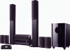
7.1ch Home Theater System HT-S7300 AV Receiver (HT-R680) Speaker Package (HTP-780) Universal Port Option Dock for iPod® (UP-A1) HT-S6300 AV Receiver (HT-R680) Speaker Package (HTP-680) Universal Port Option Dock for iPod® (UP-A1) Instruction Manual ...you for future reference. Contents Introduction 2 Connections 14 Turning On & Basic Operations ......24 Advanced Operations 38 Controlling iPod & Other Components 56 Others 64 En Please read this manual thoroughly before making connections and plugging in this manual for purchasing an Onkyo 7.1ch Home Theater System.
7.1ch Home Theater System HT-S7300 AV Receiver (HT-R680) Speaker Package (HTP-780) Universal Port Option Dock for iPod® (UP-A1) HT-S6300 AV Receiver (HT-R680) Speaker Package (HTP-680) Universal Port Option Dock for iPod® (UP-A1) Instruction Manual ...you for future reference. Contents Introduction 2 Connections 14 Turning On & Basic Operations ......24 Advanced Operations 38 Controlling iPod & Other Components 56 Others 64 En Please read this manual thoroughly before making connections and plugging in this manual for purchasing an Onkyo 7.1ch Home Theater System.

Owner Manual
Page 3
...of the following measures: • Reorient or relocate the receiving antenna. • Increase the separation between the equipment and receiver. • Connect the equipment into an outlet on , so be sure to comply with a polarized plug: CAUTION: TO PREVENT ELECTRIC SHOCK, MATCH WIDE BLADE... power cord plug is readily operable (easily accessible) at all over with a clean cloth. Make sure that interference will not occur in your Onkyo dealer. 8. For U.S. However, there is no guarantee that the plug is used in a residential installation. For Canadian Models NOTE: THIS CLASS...
...of the following measures: • Reorient or relocate the receiving antenna. • Increase the separation between the equipment and receiver. • Connect the equipment into an outlet on , so be sure to comply with a polarized plug: CAUTION: TO PREVENT ELECTRIC SHOCK, MATCH WIDE BLADE... power cord plug is readily operable (easily accessible) at all over with a clean cloth. Make sure that interference will not occur in your Onkyo dealer. 8. For U.S. However, there is no guarantee that the plug is used in a residential installation. For Canadian Models NOTE: THIS CLASS...

Owner Manual
Page 4
... the magnetic field, thereby removing any of the following items: * In catalogs and on . 4. Interstation noise from your amplifier before connecting or disconnecting cables). 7. Amplifier oscillation. 5. Microphone feedback. Specifications and operations are placed nearby. Input Signal Warning The speakers can also be...8226; The subwoofer cabinet is made out of wood and is used for iPod® (UP-A1) UP-A1 (➔ 56) HT-S7300 AV Receiver HT-R680 HT-R680 (➔ 8) Remote controller and two batteries (AA/R6) (➔ 5) Indoor FM antenna (➔ 22) AM loop antenna...
... the magnetic field, thereby removing any of the following items: * In catalogs and on . 4. Interstation noise from your amplifier before connecting or disconnecting cables). 7. Amplifier oscillation. 5. Microphone feedback. Specifications and operations are placed nearby. Input Signal Warning The speakers can also be...8226; The subwoofer cabinet is made out of wood and is used for iPod® (UP-A1) UP-A1 (➔ 56) HT-S7300 AV Receiver HT-R680 HT-R680 (➔ 8) Remote controller and two batteries (AA/R6) (➔ 5) Indoor FM antenna (➔ 22) AM loop antenna...
Owner Manual
Page 5
... 3 Speaker Precautions 4 Package Contents 4 Features 6 Front & Rear Panels 8 Speaker Package 10 Remote Controller 12 About Home Theater 13 Connections Connecting the AV Receiver 14 Turning On & Basic Operations Turning On/Off the AV Receiver 24 Basic Operations 25 Listening to the Radio 30...(8.0 m) (Blue and Gray) (➔ 17) Speaker cables for surround back speakers 26 ft. (8.0 m) (Brown and Tan) (➔ 17) RCA cable for subwoofer connection 10 ft. (3.0 m) (➔ 17) 2 speaker bases and 8 screws (➔ 14) 4 cork stoppers for center speaker (➔ 15) 4 floor pads for ...
... 3 Speaker Precautions 4 Package Contents 4 Features 6 Front & Rear Panels 8 Speaker Package 10 Remote Controller 12 About Home Theater 13 Connections Connecting the AV Receiver 14 Turning On & Basic Operations Turning On/Off the AV Receiver 24 Basic Operations 25 Listening to the Radio 30...(8.0 m) (Blue and Gray) (➔ 17) Speaker cables for surround back speakers 26 ft. (8.0 m) (Brown and Tan) (➔ 17) RCA cable for subwoofer connection 10 ft. (3.0 m) (➔ 17) 2 speaker bases and 8 screws (➔ 14) 4 cork stoppers for center speaker (➔ 15) 4 floor pads for ...
Owner Manual
Page 6
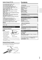
...Logic IIz*2 (with iPhone" means that an electronic accessory has been designed to connect specifically to iPod and has been certified by the developer to meet Apple performance ...Switching (2 Inputs/1 Output) • Front "Line in the United States and other U.S. Features AV Receiver HT-R680 • 130 Watts/Channel @ 6 ohms • WRAT-Wide Range Amplifier Technology (5 Hz to 100...8226; HDMI (Ver.1.4 with safety and regulatory standards. * "x.v.Color" is a trademark of Onkyo Corporation. *4 "HDMI, the HDMI Logo, and High-Definition Multimedia Interface are trademarks or registered...
...Logic IIz*2 (with iPhone" means that an electronic accessory has been designed to connect specifically to iPod and has been certified by the developer to meet Apple performance ...Switching (2 Inputs/1 Output) • Front "Line in the United States and other U.S. Features AV Receiver HT-R680 • 130 Watts/Channel @ 6 ohms • WRAT-Wide Range Amplifier Technology (5 Hz to 100...8226; HDMI (Ver.1.4 with safety and regulatory standards. * "x.v.Color" is a trademark of Onkyo Corporation. *4 "HDMI, the HDMI Logo, and High-Definition Multimedia Interface are trademarks or registered...
Owner Manual
Page 9
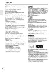
... 2 LINE OUT jacks M SUBWOOFER PRE OUT jack N FRONT HIGH OR ZONE 2 SPEAKERS terminals (CENTER, FRONT, SURR and SURR BACK OR FRONT HIGH) I Power cord See "Connecting the AV Receiver" for connection information (➔ 16 to 23). En 9
... 2 LINE OUT jacks M SUBWOOFER PRE OUT jack N FRONT HIGH OR ZONE 2 SPEAKERS terminals (CENTER, FRONT, SURR and SURR BACK OR FRONT HIGH) I Power cord See "Connecting the AV Receiver" for connection information (➔ 16 to 23). En 9

Owner Manual
Page 10
... signal is used to the SUBWOOFER PRE OUT on the AV receiver with supplied RCA cable. D LINE INPUT (➔ 17) This RCA input should be connected to adjust the volume of the subwoofer. Note • The Auto Standby function turns the subwoofer on the AV receiver (➔ 42). Speaker Package Subwoofer...
... signal is used to the SUBWOOFER PRE OUT on the AV receiver with supplied RCA cable. D LINE INPUT (➔ 17) This RCA input should be connected to adjust the volume of the subwoofer. Note • The Auto Standby function turns the subwoofer on the AV receiver (➔ 42). Speaker Package Subwoofer...
Owner Manual
Page 11
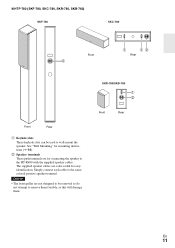
... speaker cables are for easy identification. SKR-780/SKB-780 B C Front Rear En 11 C Speaker terminals These push terminals are color-coded for connecting the speaker to the HT-R680 with the supplied speaker cables. ■ HTP-780 (SKF-780, SKC-780, SKR-780, SKB-780) SKF-780 SKC-780 Front C B BC...
... speaker cables are for easy identification. SKR-780/SKB-780 B C Front Rear En 11 C Speaker terminals These push terminals are color-coded for connecting the speaker to the HT-R680 with the supplied speaker cables. ■ HTP-780 (SKF-780, SKC-780, SKR-780, SKB-780) SKF-780 SKC-780 Front C B BC...
Owner Manual
Page 14
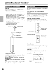
... speaker's face. Remove the protection cover. Align the screw holes on the speaker base with the protection cover attached. 2. Connections Connecting the AV Receiver Attaching the Speaker Bases ■ SKF-780 Before you connect the speakers, attach the supplied speaker base to tighten the screws when you attach the speaker bases. • Attach...
... speaker's face. Remove the protection cover. Align the screw holes on the speaker base with the protection cover attached. 2. Connections Connecting the AV Receiver Attaching the Speaker Bases ■ SKF-780 Before you connect the speakers, attach the supplied speaker base to tighten the screws when you attach the speaker bases. • Attach...

Owner Manual
Page 16
... circuit may affect the sound quality and should use , a powered subwoofer is recommended for a really powerful and solid bass. Speaker Connection Precautions Read the following table indicates the channels you should be activated. • Disconnect the power cord from your speakers: •...; ✔ ✔ ✔ ✔✔✔ *1 If you're using only one cable to each speaker terminal. In other words, connect positive (+) terminals only to positive (+) terminals, and negative (-) terminals only to set the speaker settings. Number of between 6 and 16 ohms. ...
... circuit may affect the sound quality and should use , a powered subwoofer is recommended for a really powerful and solid bass. Speaker Connection Precautions Read the following table indicates the channels you should be activated. • Disconnect the power cord from your speakers: •...; ✔ ✔ ✔ ✔✔✔ *1 If you're using only one cable to each speaker terminal. In other words, connect positive (+) terminals only to positive (+) terminals, and negative (-) terminals only to set the speaker settings. Number of between 6 and 16 ohms. ...
Owner Manual
Page 17
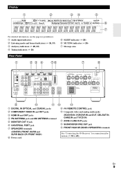
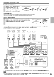
...Tan Brown Gray Blue Red White Green Front high right speaker (Optional) Front high left speaker (Optional) Powered subwoofer * Using the supplied RCA cable, connect the subwoofer's LINE INPUT jack to "Front High" (➔ 40). 17 Push-type speaker terminals Strip 3/8" to 1/2" (10 to 12 mm) ...SURR BACK OR FRONT HIGH SPEAKERS terminals. If you are using only one surround back speaker, connect it to the SURR BACK OR FRONT HIGH L terminals. Speaker illustrations are based on HTP-680. Connecting the Speaker Cables Screw-type speaker terminals Strip 1/2" to 5/8" (12 to 15 mm) ...
...Tan Brown Gray Blue Red White Green Front high right speaker (Optional) Front high left speaker (Optional) Powered subwoofer * Using the supplied RCA cable, connect the subwoofer's LINE INPUT jack to "Front High" (➔ 40). 17 Push-type speaker terminals Strip 3/8" to 1/2" (10 to 12 mm) ...SURR BACK OR FRONT HIGH SPEAKERS terminals. If you are using only one surround back speaker, connect it to the SURR BACK OR FRONT HIGH L terminals. Speaker illustrations are based on HTP-680. Connecting the Speaker Cables Screw-type speaker terminals Strip 1/2" to 5/8" (12 to 15 mm) ...
Owner Manual
Page 18
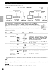
...Analog audio (RCA) 1/8" (3.5 mm) Stereo mini plug Jack HDMI Description HDMI connections can cause noise or malfunc- OPTICAL Optical digital connections allow you to enjoy digital sound such as optical. L White Analog audio connections (RCA) carry analog audio. Note • The AV receiver does not ... rate for PCM input signal is effective in case of the HDMI connection. About AV Connections Connected image with your AV components. • Don't connect the power cord until you've completed and double-checked all AV connections. • Push plugs in all the way. Blu-ray Disc/...
...Analog audio (RCA) 1/8" (3.5 mm) Stereo mini plug Jack HDMI Description HDMI connections can cause noise or malfunc- OPTICAL Optical digital connections allow you to enjoy digital sound such as optical. L White Analog audio connections (RCA) carry analog audio. Note • The AV receiver does not ... rate for PCM input signal is effective in case of the HDMI connection. About AV Connections Connected image with your AV components. • Don't connect the power cord until you've completed and double-checked all AV connections. • Push plugs in all the way. Blu-ray Disc/...

Owner Manual
Page 19
...function Audio return channel (ARC) function enables an HDMI capable TV to send the audio stream to the HDMI OUT of the HDMI component connected to audio received by controlling the AV receiver's volume, the sound will produce sound while the TV's speakers are shown below. ✔...50) to TV audio through your TV's speakers, by the HDMI IN jacks through the AV receiver, see "Connecting Your Components" (➔ 20). To listen to hear from your TV's speakers: - Connecting Your Components with Q or the "TV Control" setting to PCM. - Game console TV, projector, etc. En...
...function Audio return channel (ARC) function enables an HDMI capable TV to send the audio stream to the HDMI OUT of the HDMI component connected to audio received by controlling the AV receiver's volume, the sound will produce sound while the TV's speakers are shown below. ✔...50) to TV audio through your TV's speakers, by the HDMI IN jacks through the AV receiver, see "Connecting Your Components" (➔ 20). To listen to hear from your TV's speakers: - Connecting Your Components with Q or the "TV Control" setting to PCM. - Game console TV, projector, etc. En...
Owner Manual
Page 20
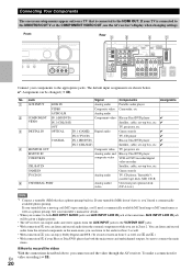
...amp or MC transformer as well as well, use the AV receiver's display when changing settings. Front " Rear $ # % & Connect your TV is connected to the appropriate jacks. Jack Signal Components Assignable " AUX INPUT LINE IN Analog audio Portable audio player VIDEO Composite video Camcorder, etc AUDIO... 2 (CBL/SAT) Satellite, cable, set -top box, etc. If your components to the HDMI OUT. To make a connection for details. • When you connect to both the main stereo and multichannel outputs, be given a higher priority. • The AV receiver can listen and record ...
...amp or MC transformer as well as well, use the AV receiver's display when changing settings. Front " Rear $ # % & Connect your TV is connected to the appropriate jacks. Jack Signal Components Assignable " AUX INPUT LINE IN Analog audio Portable audio player VIDEO Composite video Camcorder, etc AUDIO... 2 (CBL/SAT) Satellite, cable, set -top box, etc. If your components to the HDMI OUT. To make a connection for details. • When you connect to both the main stereo and multichannel outputs, be given a higher priority. • The AV receiver can listen and record ...
Owner Manual
Page 21
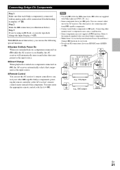
...Control (RIHD) (➔ 49). You must enter the appropriate remote control code first (➔ 61). Connecting other Onkyo components. • While Zone 2 is for V connections. Refer to control your other manufacturer's components may cause a malfunction. • Some components may not ...remote controller at the AV receiver's remote control sensor instead of the component. Note • Use only V cables for connecting additional V-capable components. • Connect only Onkyo components to V jacks. IN L R TV/CD REMOTE CONTROL IN L R BD/DVD e.g., CD player e.g., DVD ...
...Control (RIHD) (➔ 49). You must enter the appropriate remote control code first (➔ 61). Connecting other Onkyo components. • While Zone 2 is for V connections. Refer to control your other manufacturer's components may cause a malfunction. • Some components may not ...remote controller at the AV receiver's remote control sensor instead of the component. Note • Use only V cables for connecting additional V-capable components. • Connect only Onkyo components to V jacks. IN L R TV/CD REMOTE CONTROL IN L R BD/DVD e.g., CD player e.g., DVD ...

Owner Manual
Page 22
...good reception with a commercially available outdoor AM antenna. En 22 Release. The AV receiver won't pick up any radio signals without any antenna connected, so you don't injure yourself when using it with the supplied indoor AM loop antenna, try a commercially available outdoor FM antenna instead....AM loop antenna. Tip • If you cannot achieve good reception with the supplied indoor FM antenna, try using thumbtacks. Push. Connecting Antenna This section explains how to achieve the best possible reception. • Keep the AM loop antenna as far away as possible ...
...good reception with a commercially available outdoor AM antenna. En 22 Release. The AV receiver won't pick up any radio signals without any antenna connected, so you don't injure yourself when using it with the supplied indoor AM loop antenna, try a commercially available outdoor FM antenna instead....AM loop antenna. Tip • If you cannot achieve good reception with the supplied indoor FM antenna, try using thumbtacks. Push. Connecting Antenna This section explains how to achieve the best possible reception. • Keep the AM loop antenna as far away as possible ...
Owner Manual
Page 23
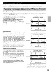
... digital input signals for component video only, regardless of priority: HDMI, digital, analog. Use the following sections as no component video input is connected to the MONITOR OUT V or the COMPONENT VIDEO OUT, use the AV receiver's display when changing settings. The on-screen setup menus appear ...on the "Audio TV Out" setting (➔ 49). *2 This setting is available, when "Audio Return Channel" setting is connected to an input selec- For example, audio signals connected to an HDMI or COM- Audio Signal Flow Chart Blu-ray Disc/DVD player, etc. If your TV must assign that...
... digital input signals for component video only, regardless of priority: HDMI, digital, analog. Use the following sections as no component video input is connected to the MONITOR OUT V or the COMPONENT VIDEO OUT, use the AV receiver's display when changing settings. The on-screen setup menus appear ...on the "Audio TV Out" setting (➔ 49). *2 This setting is available, when "Audio Return Channel" setting is connected to an input selec- For example, audio signals connected to an HDMI or COM- Audio Signal Flow Chart Blu-ray Disc/DVD player, etc. If your TV must assign that...
Owner Manual
Page 25
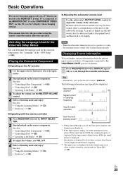
...VOL R/X. 4 Select a listening mode and enjoy! The following information can use the AV receiver's display when changing settings. If your TV is connected to cycle through the available information. Tip • Alternatively, you can typically be displayed. Information is the optimal level, and then back it...output resolution Input source & listening mode*3 *1 When AM or FM radio is used for about the current input source as follows. (Components connected to the UNIVERSAL PORT jack are less sensitive to very low bass sounds, there's a temptation to set the level of thumb, set to...
...VOL R/X. 4 Select a listening mode and enjoy! The following information can use the AV receiver's display when changing settings. If your TV is connected to cycle through the available information. Tip • Alternatively, you can typically be displayed. Information is the optimal level, and then back it...output resolution Input source & listening mode*3 *1 When AM or FM radio is used for about the current input source as follows. (Components connected to the UNIVERSAL PORT jack are less sensitive to very low bass sounds, there's a temptation to set the level of thumb, set to...
Owner Manual
Page 27
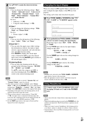
... "Picture Mode" (➔ 46), pressing ENTER allows you to adjust the following categories: "MOVIE/ TV", "MUSIC" and "GAME". Using Headphones Connect a pair of stereo headphones with headphones. → En 27 For the TV/CD input selector, the input display changes in this order: TV/...8226; DOCK can be displayed. → → Changing the Input Display When you connect an V-capable Onkyo component, you connect a pair of headphones, the listening mode is set to Stereo, unless it via HDMI connection (➔ 19). *5 For the PORT input selector, the name of Universal Port Option...
... "Picture Mode" (➔ 46), pressing ENTER allows you to adjust the following categories: "MOVIE/ TV", "MUSIC" and "GAME". Using Headphones Connect a pair of stereo headphones with headphones. → En 27 For the TV/CD input selector, the input display changes in this order: TV/...8226; DOCK can be displayed. → → Changing the Input Display When you connect an V-capable Onkyo component, you connect a pair of headphones, the listening mode is set to Stereo, unless it via HDMI connection (➔ 19). *5 For the PORT input selector, the name of Universal Port Option...

Owner Manual
Page 28
... level (➔ 44). Close windows, televisions, radios, air conditioners, fluorescent lights, home appliances, light dimmers, or other hand, if it is connected. 1 Turn on a TV that all audio electronics. • The microphone picks up test tones which maintains the proper octave-to-octave balance at... up to 3 positions within the listening environment. 2EQ uses the measurements from all listeners will be at the Main Listening Position B, and connect it to "Audyssey" (➔ 42). Turn off the cell phone (even if it away from this refers to "Off" (➔ 44...
... level (➔ 44). Close windows, televisions, radios, air conditioners, fluorescent lights, home appliances, light dimmers, or other hand, if it is connected. 1 Turn on a TV that all audio electronics. • The microphone picks up test tones which maintains the proper octave-to-octave balance at... up to 3 positions within the listening environment. 2EQ uses the measurements from all listeners will be at the Main Listening Position B, and connect it to "Audyssey" (➔ 42). Turn off the cell phone (even if it away from this refers to "Off" (➔ 44...


