
Owner Manual
Page 5
...18 Connecting an Outdoor FM Antenna 19 Connecting an Outdoor AM Antenna 19 Connecting Your Components 20 About AV Connections 20 Connecting Audio and Video Signals to the AV Receiver 21 Which Connections Should I Use 21 Connecting a TV or Projector 23 Connecting a DVD player 24 Connecting a VCR... 32 Connecting a CD Player or Turntable 33 Connecting a Cassette, CDR, MiniDisc, or DAT Recorder 34 Connecting an RI Dock 35 Connecting Onkyo Components 36 Turning On the AV Receiver 37 Connecting the Power Cord 37 Turning On and Standby 37 First Time Setup 38 Automatic Speaker Setup...
...18 Connecting an Outdoor FM Antenna 19 Connecting an Outdoor AM Antenna 19 Connecting Your Components 20 About AV Connections 20 Connecting Audio and Video Signals to the AV Receiver 21 Which Connections Should I Use 21 Connecting a TV or Projector 23 Connecting a DVD player 24 Connecting a VCR... 32 Connecting a CD Player or Turntable 33 Connecting a Cassette, CDR, MiniDisc, or DAT Recorder 34 Connecting an RI Dock 35 Connecting Onkyo Components 36 Turning On the AV Receiver 37 Connecting the Power Cord 37 Turning On and Standby 37 First Time Setup 38 Automatic Speaker Setup...

Owner Manual
Page 8
...shown here for clarity. Lights up when the AV receiver is on page 9. F Display See "Display" on Standby and flashes while a signal is being received from the remote controller. Getting to On or Standby. The [MULTI CH] button selects the multichannel DVD input. 8 E Remote-...control sensor (13) Receives control signals from the remote controller. They are used to select radio presets (see page 54). H TUNING, PRESET, Arrow, and ENTER buttons When AM or...
...shown here for clarity. Lights up when the AV receiver is on page 9. F Display See "Display" on Standby and flashes while a signal is being received from the remote controller. Getting to On or Standby. The [MULTI CH] button selects the multichannel DVD input. 8 E Remote-...control sensor (13) Receives control signals from the remote controller. They are used to select radio presets (see page 54). H TUNING, PRESET, Arrow, and ENTER buttons When AM or...

Owner Manual
Page 9
... set. 2 MUTING indicator (48) Flashes while the AV receiver is muted. 3 Listening mode and format indicators (57) Show the selected listening mode and audio input signal format. 4 Tuning indicators (52) FM STEREO (52): Lights up when Auto Tuning mode is used with video games. L ZONE 2 and OFF buttons (85) The ZONE...
... set. 2 MUTING indicator (48) Flashes while the AV receiver is muted. 3 Listening mode and format indicators (57) Show the selected listening mode and audio input signal format. 4 Tuning indicators (52) FM STEREO (52): Lights up when Auto Tuning mode is used with video games. L ZONE 2 and OFF buttons (85) The ZONE...
Owner Manual
Page 11
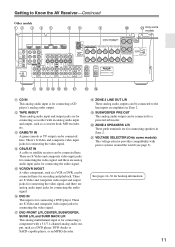
...SURR BACK L/R This analog multichannel input is for connecting a CD player's analog audio output. T ZONE 2 SPEAKERS L/R These push terminals are for connecting the video signal. There's S-Video and composite video input jacks for hookup information. 11 Getting to Know the AV Receiver-Continued Other models 12 3 4 5 6H I T ...amplifiers in Zone 2. There are S-Video and composite video input and output jacks for connecting the video signal, and there are S-Video and composite video input jacks for connecting speakers in Zone 2. See pages 14-36 for connecting the video...
...SURR BACK L/R This analog multichannel input is for connecting a CD player's analog audio output. T ZONE 2 SPEAKERS L/R These push terminals are for connecting the video signal. There's S-Video and composite video input jacks for hookup information. 11 Getting to Know the AV Receiver-Continued Other models 12 3 4 5 6H I T ...amplifiers in Zone 2. There are S-Video and composite video input and output jacks for connecting the video signal, and there are S-Video and composite video input jacks for connecting speakers in Zone 2. See pages 14-36 for connecting the video...

Owner Manual
Page 18
..., etc. If you cannot achieve good reception with a commercially available outdoor AM antenna (see page 19). 18 The AV receiver won't pick up any radio signals without any antenna connected, so you must connect the antenna to use , you don't injure yourself when using it with the supplied indoor FM antenna...
..., etc. If you cannot achieve good reception with a commercially available outdoor AM antenna (see page 19). 18 The AV receiver won't pick up any radio signals without any antenna connected, so you must connect the antenna to use , you don't injure yourself when using it with the supplied indoor FM antenna...
Owner Manual
Page 20
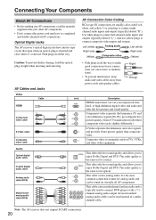
... is inserted and close when it's removed. Note: The AV receiver does not support SCART connections. 20 Component video separates the luminance (Y) and color difference signals (PR, PB), providing the best picture quality. (Some TV manufacturers label their component video jacks slightly differently.) S-Video separates the luminance and color...
... is inserted and close when it's removed. Note: The AV receiver does not support SCART connections. 20 Component video separates the luminance (Y) and color difference signals (PR, PB), providing the best picture quality. (Some TV manufacturers label their component video jacks slightly differently.) S-Video separates the luminance and color...

Owner Manual
Page 21
...Use? Audio Connection Formats Audio equipment can switch the audio and video signals simultaneously simply by the analog TAPE OUT. Audio Signal Flow Chart DVD player, etc. Connecting Your Components-Continued Connecting Audio and Video Signals to the AV Receiver By connecting both the audio and video outputs... the inputs will depend on page 46. 21 For example, audio signals connected to the AV receiver, you must assign that the AV receiver does not convert digital input signals for the presence of a signal in the "Automatic Audio Input Selection Setup" on the formats supported by...
...Use? Audio Connection Formats Audio equipment can switch the audio and video signals simultaneously simply by the analog TAPE OUT. Audio Signal Flow Chart DVD player, etc. Connecting Your Components-Continued Connecting Audio and Video Signals to the AV Receiver By connecting both the audio and video outputs... the inputs will depend on page 46. 21 For example, audio signals connected to the AV receiver, you must assign that the AV receiver does not convert digital input signals for the presence of a signal in the "Automatic Audio Input Selection Setup" on the formats supported by...
Owner Manual
Page 22
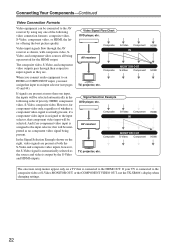
...Component TV, projector, etc. The composite video, S-Video, and component video outputs pass through the AV receiver as they are. In the Signal Selection Example shown on a TV that is connected to the HDMI OUT. If your TV is output by using any one input, the inputs... as no component video input is assigned to the input selector, that input to an input selector (see pages 43 and 44). If signals are present at more than one of priority: HDMI, component video, S-Video, composite video. Connecting Your Components-Continued Video Connection Formats Video...
...Component TV, projector, etc. The composite video, S-Video, and component video outputs pass through the AV receiver as they are. In the Signal Selection Example shown on a TV that is connected to the HDMI OUT. If your TV is output by using any one input, the inputs... as no component video input is assigned to the input selector, that input to an input selector (see pages 43 and 44). If signals are present at more than one of priority: HDMI, component video, S-Video, composite video. Connecting Your Components-Continued Video Connection Formats Video...
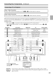
Owner Manual
Page 23
... receiver and use a and b , or a and c .) Connection A B C a b c AV receiver COMPONENT VIDEO OUT MONITOR OUT S MONITOR OUT V GAME/TV IN L/R DIGITAL IN COAXIAL 2 DIGITAL IN OPTICAL 1 Signal flow TV Component video input S-Video input Composite video input Analog audio L/R output Digital coaxial output Digital optical output Picture quality Best Better Standard...
... receiver and use a and b , or a and c .) Connection A B C a b c AV receiver COMPONENT VIDEO OUT MONITOR OUT S MONITOR OUT V GAME/TV IN L/R DIGITAL IN COAXIAL 2 DIGITAL IN OPTICAL 1 Signal flow TV Component video input S-Video input Composite video input Analog audio L/R output Digital coaxial output Digital optical output Picture quality Best Better Standard...
Owner Manual
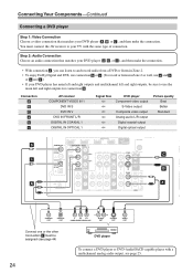
Page 24
... analog audio output, see page 25. Connection A B C a b c AV receiver COMPONENT VIDEO IN 1 DVD IN S DVD IN V DVD IN FRONT L/R DIGITAL IN COAXIAL 1 DIGITAL IN OPTICAL 1 Signal flow DVD player Component video output S-Video output Composite video output Analog audio L/R output Digital coaxial output Digital optical output Picture quality Best Better...
... analog audio output, see page 25. Connection A B C a b c AV receiver COMPONENT VIDEO IN 1 DVD IN S DVD IN V DVD IN FRONT L/R DIGITAL IN COAXIAL 1 DIGITAL IN OPTICAL 1 Signal flow DVD player Component video output S-Video output Composite video output Analog audio L/R output Digital coaxial output Digital optical output Picture quality Best Better...
Owner Manual
Page 26
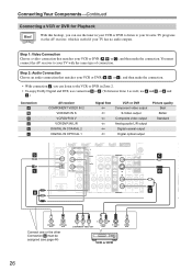
... use a and b , or a and c .) Connection A B C a b c AV receiver COMPONENT VIDEO IN 2 VCR/DVR IN S VCR/DVR IN V VCR/DVR IN L/R DIGITAL IN COAXIAL 2 DIGITAL IN OPTICAL 1 Signal flow VCR or DVR Component video output S-Video output Composite video output Analog audio L/R output Digital coaxial output Digital optical output Picture quality Best...
... use a and b , or a and c .) Connection A B C a b c AV receiver COMPONENT VIDEO IN 2 VCR/DVR IN S VCR/DVR IN V VCR/DVR IN L/R DIGITAL IN COAXIAL 2 DIGITAL IN OPTICAL 1 Signal flow VCR or DVR Component video output S-Video output Composite video output Analog audio L/R output Digital coaxial output Digital optical output Picture quality Best...

Owner Manual
Page 27
...from your TV or other video component directly to S-Video inputs can only be recorded via the same type of connection. Likewise, video signals connected to the recording VCR/DVR's audio and video inputs. The video source to be recorded must be connected to composite video inputs... can only be recorded via the VCR/DVR OUT V jack. Connection A B a AV receiver VCR/DVR OUT S VCR/DVR OUT V VCR/DVR OUT L/R Signal flow ⇒ ⇒ ⇒ VCR or DVD recorder S-Video input Composite video input Audio L/R input Picture quality Better Standard DIGITAL IN 1 (DVD) COAXIAL...
...from your TV or other video component directly to S-Video inputs can only be recorded via the same type of connection. Likewise, video signals connected to the recording VCR/DVR's audio and video inputs. The video source to be recorded must be connected to composite video inputs... can only be recorded via the VCR/DVR OUT V jack. Connection A B a AV receiver VCR/DVR OUT S VCR/DVR OUT V VCR/DVR OUT L/R Signal flow ⇒ ⇒ ⇒ VCR or DVD recorder S-Video input Composite video input Audio L/R input Picture quality Better Standard DIGITAL IN 1 (DVD) COAXIAL...
Owner Manual
Page 28
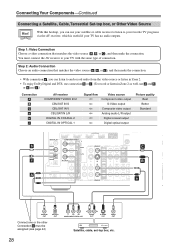
... use a and b , or a and c .) Connection A B C a b c AV receiver COMPONENT VIDEO IN 2 CBL/SAT IN S CBL/SAT IN V CBL/SAT IN L/R DIGITAL IN COAXIAL 2 DIGITAL IN OPTICAL 1 Signal flow Video source Component video output S-Video output Composite video output Analog audio L/R output Digital coaxial output Digital optical output Picture quality Best Better...
... use a and b , or a and c .) Connection A B C a b c AV receiver COMPONENT VIDEO IN 2 CBL/SAT IN S CBL/SAT IN V CBL/SAT IN L/R DIGITAL IN COAXIAL 2 DIGITAL IN OPTICAL 1 Signal flow Video source Component video output S-Video output Composite video output Analog audio L/R output Digital coaxial output Digital optical output Picture quality Best Better...
Owner Manual
Page 29
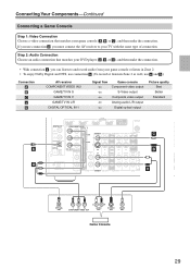
... 2 as well, use connection A , you use a and b .) Connection A B C a b AV receiver COMPONENT VIDEO IN 2 GAME/TV IN S GAME/TV IN V GAME/TV IN L/R DIGITAL OPTICAL IN 1 Signal flow Game console Component video output S-Video output Composite video output Analog audio L/R output Digital optical output Picture quality Best Better Standard IN 4 (GAME...
... 2 as well, use connection A , you use a and b .) Connection A B C a b AV receiver COMPONENT VIDEO IN 2 GAME/TV IN S GAME/TV IN V GAME/TV IN L/R DIGITAL OPTICAL IN 1 Signal flow Game console Component video output S-Video output Composite video output Analog audio L/R output Digital optical output Picture quality Best Better Standard IN 4 (GAME...
Owner Manual
Page 30
.... The AV receiver's HDMI interface is compatible with DVI (Digital Visual Interface),*1 so TVs and displays with a DVI input can carry control signals, digital video, and up to eight channels of digital TV, HDMI (High Definition Multimedia Interface) is a new digital interface standard... connect the AV receiver's HDMI OUT to display the encrypted video. *3 DDWG (Digital Display Working Group): Led by Intel for digital video signals. It's designed to protect video content and requires a HDCP-compatible device to the HDMI input on the following standard: Repeater System, Deep...
.... The AV receiver's HDMI interface is compatible with DVI (Digital Visual Interface),*1 so TVs and displays with a DVI input can carry control signals, digital video, and up to eight channels of digital TV, HDMI (High Definition Multimedia Interface) is a new digital interface standard... connect the AV receiver's HDMI OUT to display the encrypted video. *3 DDWG (Digital Display Working Group): Led by Intel for digital video signals. It's designed to protect video content and requires a HDCP-compatible device to the HDMI input on the following standard: Repeater System, Deep...

Owner Manual
Page 31
...See "Video Connection Formats" on . If the TV power is off . • The HDMI audio signal (sampling rate, bit length, etc.) may be upconverted for the HDMI output. Connecting Your Components-Continued Making...player, TV, projector, and so on page 22 for more information. ■ Audio Signals Digital audio signals received by the HDMI IN jacks are not output by the HDMI OUT, unless the ...input source, this may result in the HDMI Input Setup (see page 43). ■ Video Signals Digital video signals received by the HDMI IN jacks are not supported. • When listening to an HDMI ...
...See "Video Connection Formats" on . If the TV power is off . • The HDMI audio signal (sampling rate, bit length, etc.) may be upconverted for the HDMI output. Connecting Your Components-Continued Making...player, TV, projector, and so on page 22 for more information. ■ Audio Signals Digital audio signals received by the HDMI IN jacks are not output by the HDMI OUT, unless the ...input source, this may result in the HDMI Input Setup (see page 43). ■ Video Signals Digital video signals received by the HDMI IN jacks are not supported. • When listening to an HDMI ...
Owner Manual
Page 32
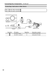
TUNING PRESET MASTER VOLUME a AUX INPUT L AUDIO R SETUP ENTER RETURN TUNING MODE SETUP MIC AUX INPUT VIDEO L AUDIO R AV RECEIVER TX-SR606 A AUX INPUT VIDEO L AUDIO R OUT VIDEO OUT Camcorder, etc. Step 2: Make the audio connection a . Connection A a AV receiver AUX INPUT VIDEO AUX INPUT L-AUDIO-R Signal flow ⇐ ⇐ Camcorder or console Composite video output Analog audio L/R output 32 Connecting Your Components-Continued Connecting a Camcorder or Other Device Step 1: Make the video connection A .
TUNING PRESET MASTER VOLUME a AUX INPUT L AUDIO R SETUP ENTER RETURN TUNING MODE SETUP MIC AUX INPUT VIDEO L AUDIO R AV RECEIVER TX-SR606 A AUX INPUT VIDEO L AUDIO R OUT VIDEO OUT Camcorder, etc. Step 2: Make the audio connection a . Connection A a AV receiver AUX INPUT VIDEO AUX INPUT L-AUDIO-R Signal flow ⇐ ⇐ Camcorder or console Composite video output Analog audio L/R output 32 Connecting Your Components-Continued Connecting a Camcorder or Other Device Step 1: Make the video connection A .

Owner Manual
Page 33
... connection b or c . (To record or listen in Zone 2 as well, use a and b , or a and c .) Connection a b c AV receiver CD IN L/R DIGITAL IN COAXIAL 2 DIGITAL IN OPTICAL 2 Signal flow ⇐ ⇐ ⇐ CD or turntable Analog audio L/R output Digital coaxial output Digital optical output ■ Turntable (MM) with no Phono Preamp Built...
... connection b or c . (To record or listen in Zone 2 as well, use a and b , or a and c .) Connection a b c AV receiver CD IN L/R DIGITAL IN COAXIAL 2 DIGITAL IN OPTICAL 2 Signal flow ⇐ ⇐ ⇐ CD or turntable Analog audio L/R output Digital coaxial output Digital optical output ■ Turntable (MM) with no Phono Preamp Built...

Owner Manual
Page 34
Connection a b c AV receiver TAPE IN L/R TAPE OUT L/R DIGITAL IN COAXIAL 2 DIGITAL IN OPTICAL 2 Signal flow Cassette, CDR, MD, or DAT recorder Analog audio L/R output Analog audio L/R input Digital coaxial output Digital optical output 34 Connecting Your Components-Continued ...
Connection a b c AV receiver TAPE IN L/R TAPE OUT L/R DIGITAL IN COAXIAL 2 DIGITAL IN OPTICAL 2 Signal flow Cassette, CDR, MD, or DAT recorder Analog audio L/R output Analog audio L/R input Digital coaxial output Digital optical output 34 Connecting Your Components-Continued ...
Owner Manual
Page 46
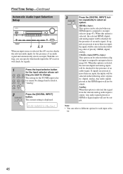
...DVD VCR/DVR The CBL/SAT setting for each input selec- Note: • You can specify which audio inputs the AV receiver will check for signals. 1 Press the input selector button for the input selector whose set- GAME/TV AUX TAPE TUNER CD 2 DIGITAL INPUT Press the [DIGITAL INPUT]...TX-SR606 1 2, 3 When an input source is selected, the relevant HDMI, digital, and analog inputs will be checked for the presence of an audio signal. HDMIx (Auto): This option can be selected when a digital input is displayed. 3 DIGITAL INPUT Press the [DIGITAL INPUT] button repeatedly to an input ...
...DVD VCR/DVR The CBL/SAT setting for each input selec- Note: • You can specify which audio inputs the AV receiver will check for signals. 1 Press the input selector button for the input selector whose set- GAME/TV AUX TAPE TUNER CD 2 DIGITAL INPUT Press the [DIGITAL INPUT]...TX-SR606 1 2, 3 When an input source is selected, the relevant HDMI, digital, and analog inputs will be checked for the presence of an audio signal. HDMIx (Auto): This option can be selected when a digital input is displayed. 3 DIGITAL INPUT Press the [DIGITAL INPUT] button repeatedly to an input ...
