
English Manual
Page 3
... openings. Failure to the control system of the treadmill. Keep children under the treadmill. 11. Never move the walking belt while the power is capable of high speeds. Athletic support clothes are adequately informed of all warnings and precautions. The treadmill is turned off. The pulse sensor is damaged, the walking belt may slow, accelerate, or stop procedure before using the treadmill. 17. Use the treadmill only as an exercise aid in determining heart rate...
... openings. Failure to the control system of the treadmill. Keep children under the treadmill. 11. Never move the walking belt while the power is capable of high speeds. Athletic support clothes are adequately informed of all warnings and precautions. The treadmill is turned off. The pulse sensor is damaged, the walking belt may slow, accelerate, or stop procedure before using the treadmill. 17. Use the treadmill only as an exercise aid in determining heart rate...

English Manual
Page 4
... exercising, stop immediately and cool down. Servicing other than the procedures in this manual. 19. Always remove the key, unplug the power cord, and press the power switch into any object into the off position when the treadmill is not in serious injury or death. Do not attempt to raise, lower, or move the treadmill. 21. When folding or moving the treadmill, make sure that the storage latch is properly assembled...
... exercising, stop immediately and cool down. Servicing other than the procedures in this manual. 19. Always remove the key, unplug the power cord, and press the power switch into any object into the off position when the treadmill is not in serious injury or death. Do not attempt to raise, lower, or move the treadmill. 21. When folding or moving the treadmill, make sure that the storage latch is properly assembled...

English Manual
Page 5
... manual. Accessory Tray Handrail Upright Walking Belt Foot Rail Idler Roller Adjustment Bolts Console Pulse Sensor Key/Clip Power Switch Power Cord Platform Cushion 5 For your workouts at home more effective and enjoyable. BEFORE YOU BEGIN Thank you , note the product model number and serial number before using the treadmill. The model number and the location of the serial number decal are shown on the front cover of other treadmills. To help us . The T 4.0 treadmill offers a selection of this manual. ing this manual...
... manual. Accessory Tray Handrail Upright Walking Belt Foot Rail Idler Roller Adjustment Bolts Console Pulse Sensor Key/Clip Power Switch Power Cord Platform Cushion 5 For your workouts at home more effective and enjoyable. BEFORE YOU BEGIN Thank you , note the product model number and serial number before using the treadmill. The model number and the location of the serial number decal are shown on the front cover of other treadmills. To help us . The T 4.0 treadmill offers a selection of this manual. ing this manual...

English Manual
Page 10
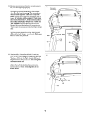
... Right Handrail (101). Console Wire 108 73 34 Tie If necessary, adjust the Console Frame (111) to the position shown. Start all three Bolts, and then tighten each of the Right Handrail as described above. 9. Remove the tie from the Right Handrail. Tighten the #8 x 1" Screws (107). Set the console assembly face down to the console assembly with a 1/4" Star Washer (73). If necessary, press the 10 M8...
... Right Handrail (101). Console Wire 108 73 34 Tie If necessary, adjust the Console Frame (111) to the position shown. Start all three Bolts, and then tighten each of the Right Handrail as described above. 9. Remove the tie from the Right Handrail. Tighten the #8 x 1" Screws (107). Set the console assembly face down to the console assembly with a 1/4" Star Washer (73). If necessary, press the 10 M8...
English Manual
Page 11
... 11 Connect the Upright Wire (88) to the console wire. Set the console assembly on the Right Upright (89) and the Left Upright (not shown). 11. See the inset drawing. If they do not, turn one connector and try again. Do not tighten the Patch Bolts yet. Attach the Left Handrail (not shown) as shown. Then, insert the connectors into the Right Upright (89). Remove the...
... 11 Connect the Upright Wire (88) to the console wire. Set the console assembly on the Right Upright (89) and the Left Upright (not shown). 11. See the inset drawing. If they do not, turn one connector and try again. Do not tighten the Patch Bolts yet. Attach the Left Handrail (not shown) as shown. Then, insert the connectors into the Right Upright (89). Remove the...

English Manual
Page 13
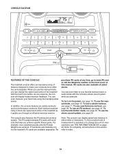
... Metal Screw Grounding Plug The temporary adapter should malfunction or break down, grounding provides a path of damaging your treadmill (see drawing 1). The surge suppressor must be used only until a properly grounded outlet (see drawing 2). There must be held in accordance with highperformance lubricant. The adapter must be damaged by a qualified electrician. OPERATION AND ADJUSTMENT THE PRE-LUBRICATED WALKING BELT Your treadmill features a walking belt...
... Metal Screw Grounding Plug The temporary adapter should malfunction or break down, grounding provides a path of damaging your treadmill (see drawing 1). The surge suppressor must be used only until a properly grounded outlet (see drawing 2). There must be held in accordance with highperformance lubricant. The adapter must be damaged by a qualified electrician. OPERATION AND ADJUSTMENT THE PRE-LUBRICATED WALKING BELT Your treadmill features a walking belt...
English Manual
Page 14
... information mode, see page 20. To Note: The console can even listen to your favorite workout music or audio books with workouts that help you achieve specific fitness goals. Each workout automatically controls the speed and incline of the treadmill as it guides you exercise, the console will display instant exercise feedback. You can display speed and distance in this manual. iFit workouts automatically control the treadmill. You can change the unit of measurement, see page 15. iFit cards...
... information mode, see page 20. To Note: The console can even listen to your favorite workout music or audio books with workouts that help you achieve specific fitness goals. Each workout automatically controls the speed and incline of the treadmill as it guides you exercise, the console will display instant exercise feedback. You can display speed and distance in this manual. iFit workouts automatically control the treadmill. You can change the unit of measurement, see page 15. iFit cards...

English Manual
Page 15
... power switch on the foot rails of 0.5 mph. If the displays light as soon as you exercise, change by pressing the Speed increase and decrease buttons. Find the clip attached to the key (see THE INFORMATION MODE on page 20 to turn off the demo mode. Then, insert the key into the console. As you plug in the reset position. The first time you may take a moment for a few steps...
... power switch on the foot rails of 0.5 mph. If the displays light as soon as you exercise, change by pressing the Speed increase and decrease buttons. Find the clip attached to the key (see THE INFORMATION MODE on page 20 to turn off the demo mode. Then, insert the key into the console. As you plug in the reset position. The first time you may take a moment for a few steps...

English Manual
Page 16
... changes. Note: When a workout is detected, a heart symbol in the lower right display will again begin to the lowest setting. Measure your heart rate will show the incline of the walking belt. Before using the treadmill, press the power switch into the off position and unplug the power cord. When your pulse is selected, the lower left display will be shown. Step onto the foot rails, press the Stop button, and adjust the incline of the buttons, the treadmill...
... changes. Note: When a workout is detected, a heart symbol in the lower right display will again begin to the lowest setting. Measure your heart rate will show the incline of the walking belt. Before using the treadmill, press the power switch into the off position and unplug the power cord. When your pulse is selected, the lower left display will be shown. Step onto the foot rails, press the Stop button, and adjust the incline of the buttons, the treadmill...

English Manual
Page 17
... you and the treadmill will automatically adjust to a stop the workout at any time, press the Stop button. The flashing segment of the profile represents the current segment of the flashing segment indicates the speed setting for consecutive segments. 5. HOW TO USE A CALORIE WORKOUT 1. Insert the key into one incline setting are finished exercising, remove the key from the console. See HOW TO TURN ON THE POWER on page 15...
... you and the treadmill will automatically adjust to a stop the workout at any time, press the Stop button. The flashing segment of the profile represents the current segment of the flashing segment indicates the speed setting for consecutive segments. 5. HOW TO USE A CALORIE WORKOUT 1. Insert the key into one incline setting are finished exercising, remove the key from the console. See HOW TO TURN ON THE POWER on page 15...

English Manual
Page 18
... segment of the workout begins, the treadmill will flash in the display and the last segment ends. See step 3 on page 16. 7. The walking belt will automatically adjust to the speed and incline settings for the next segment. 6. Press the Start button or the Speed increase button to move at any time, press the Stop button. Note: The same speed setting and/or incline setting may be programmed for each segment, a series of tones will...
... segment of the workout begins, the treadmill will flash in the display and the last segment ends. See step 3 on page 16. 7. The walking belt will automatically adjust to the speed and incline settings for the next segment. 6. Press the Start button or the Speed increase button to move at any time, press the Stop button. Note: The same speed setting and/or incline setting may be programmed for each segment, a series of tones will...

English Manual
Page 19
... remove iFit cards from the console. To purchase iFit cards, go to start the workout. In addition, a profile of the speed settings of this manual. Measure your progress with the displays. Press the Start button or the Speed increase button to www.iFit.com or call the telephone number on the front cover of the workout will begin walking. When the next segment of the workout begins, the treadmill will automatically adjust to the first speed...
... remove iFit cards from the console. To purchase iFit cards, go to start the workout. In addition, a profile of the speed settings of this manual. Measure your progress with the displays. Press the Start button or the Speed increase button to www.iFit.com or call the telephone number on the front cover of the workout will begin walking. When the next segment of the workout begins, the treadmill will automatically adjust to the first speed...

English Manual
Page 20
... the treadmill is fully inserted. Then, plug the audio wire into the MP3 jack. To turn on the console. 20 Next, press the Play button on , a "d" will not function. If you remove the key, the displays will remain lit, although the buttons will appear in the lower right display. THE INFORMATION MODE The console features an information mode that keeps track of the total distance that the walking belt has moved and the total number...
... the treadmill is fully inserted. Then, plug the audio wire into the MP3 jack. To turn on the console. 20 Next, press the Play button on , a "d" will not function. If you remove the key, the displays will remain lit, although the buttons will appear in the lower right display. THE INFORMATION MODE The console features an information mode that keeps track of the total distance that the walking belt has moved and the total number...
English Manual
Page 21
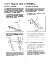
... incline to the desired location. CAUTION: Make sure that the latch knob is locked in the storage position. Place one of direct sunlight. if necessary, push the frame forward slightly. CAUTION: Do not move the treadmill. 1. Hold the metal frame firmly in temperatures above 85° F (30° C). 2. See drawing 1 at the left ; Then, remove the key and unplug the power cord...
... incline to the desired location. CAUTION: Make sure that the latch knob is locked in the storage position. Place one of direct sunlight. if necessary, push the frame forward slightly. CAUTION: Do not move the treadmill. 1. Hold the metal frame firmly in temperatures above 85° F (30° C). 2. See drawing 1 at the left ; Then, remove the key and unplug the power cord...

English Manual
Page 22
... is required. 89 Then, raise the Uprights (85, 89). 85 84 A A 22 To reset the switch, wait for five minutes, and then plug it , wait for five minutes and then press the switch back in . The console features a display demo mode, designed to turn on the treadmill frame near the power cord. PROBLEM: The displays of this manual. Remove the key from the console. Note: A Phillips screwdriver with GFCI-equipped...
... is required. 89 Then, raise the Uprights (85, 89). 85 84 A A 22 To reset the switch, wait for five minutes, and then plug it , wait for five minutes and then press the switch back in . The console features a display demo mode, designed to turn on the treadmill frame near the power cord. PROBLEM: The displays of this manual. Remove the key from the console. Note: A Phillips screwdriver with GFCI-equipped...

English Manual
Page 23
... Pan Screws (not shown), if necessary. Use only a single-outlet surge suppressor that the gap between the Magnet and the Reed Switch is aligned with the Reed Switch. b. Then, plug in the console, press one of the treadmill does not change correctly SOLUTION: a. Reattach the Motor Hood (not shown). With the key in the power cord, insert the key, and run the treadmill for a correct speed reading. 1/8 in . PROBLEM: The walking belt...
... Pan Screws (not shown), if necessary. Use only a single-outlet surge suppressor that the gap between the Magnet and the Reed Switch is aligned with the Reed Switch. b. Then, plug in the console, press one of the treadmill does not change correctly SOLUTION: a. Reattach the Motor Hood (not shown). With the key in the power cord, insert the key, and run the treadmill for a correct speed reading. 1/8 in . PROBLEM: The walking belt...
English Manual
Page 24
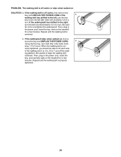
.... PROBLEM: The walking belt is off-center or slips when walked on , first re- if the walking belt has shifted to the right, turn the bolt counterclockwise 1/2 of the walking belt 2 to turn the left idler roller bolt clockwise 1/2 of a turn . If the walking belt slips when walked on SOLUTION: a. Then, plug in . (5 to lift each side of a turn . b. When the walking belt is off the walk- Be care- move the key and UNPLUG THE POWER CORD. rectly tightened...
.... PROBLEM: The walking belt is off-center or slips when walked on , first re- if the walking belt has shifted to the right, turn the bolt counterclockwise 1/2 of the walking belt 2 to turn the left idler roller bolt clockwise 1/2 of a turn . If the walking belt slips when walked on SOLUTION: a. Then, plug in . (5 to lift each side of a turn . b. When the walking belt is off the walk- Be care- move the key and UNPLUG THE POWER CORD. rectly tightened...
English Manual
Page 25
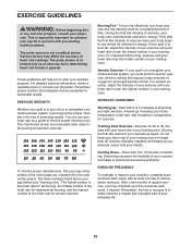
... goal is to five workouts each week, with your heart rate near the middle number in your training zone. The pulse sensor is near the lowest number in general. The chart below shows recommended heart rates for exercise. Training Zone Exercise-Exercise for energy. For maximum fat burning, exercise with at the bottom of your exercise program, do not keep your heart rate in your physician. EXERCISE GUIDELINES WARNING: Before beginning...
... goal is to five workouts each week, with your heart rate near the middle number in your training zone. The pulse sensor is near the lowest number in general. The chart below shows recommended heart rates for exercise. Training Zone Exercise-Exercise for energy. For maximum fat burning, exercise with at the bottom of your exercise program, do not keep your heart rate in your physician. EXERCISE GUIDELINES WARNING: Before beginning...
English Manual
Page 26
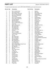
... Magnet Motor Belt Drive Roller/Pulley Walking Belt Walking Platform Frame Roller Bracket Right Foot Rail Latch Cap Storage Latch Latch Knob Right Foot Idler Roller Roller Bracket Plate Left Foot Console Clamp Motor Hood Drive Motor Lift Frame Cable Tie Reed Switch Reed Switch Clamp Frame Spacer 1/4" Star Washer Lift Frame Incline Stop Bracket Lift Frame/Roller Ground Wire Lift Motor Lift Motor Spacer Lift Motor Wire Controller Power Cord Power Cord Grommet Power Switch Belly Pan Left Upright Left Upright Spacer Base Cap Upright Wire Right Upright Bolt Spacer Right Upright Spacer Base...
... Magnet Motor Belt Drive Roller/Pulley Walking Belt Walking Platform Frame Roller Bracket Right Foot Rail Latch Cap Storage Latch Latch Knob Right Foot Idler Roller Roller Bracket Plate Left Foot Console Clamp Motor Hood Drive Motor Lift Frame Cable Tie Reed Switch Reed Switch Clamp Frame Spacer 1/4" Star Washer Lift Frame Incline Stop Bracket Lift Frame/Roller Ground Wire Lift Motor Lift Motor Spacer Lift Motor Wire Controller Power Cord Power Cord Grommet Power Switch Belly Pan Left Upright Left Upright Spacer Base Cap Upright Wire Right Upright Bolt Spacer Right Upright Spacer Base...

English Manual
Page 32
... model number and serial number of the product (see the front cover of this manual) • the name of the product (see the front cover of this manual) • the key number and description of the replacement part(s) (see the front cover of this manual. ICONʼs obligation under normal use or performance of whatsoever nature. This warranty does not extend to any implied warranties of merchantability or fitness...
... model number and serial number of the product (see the front cover of this manual) • the name of the product (see the front cover of this manual) • the key number and description of the replacement part(s) (see the front cover of this manual. ICONʼs obligation under normal use or performance of whatsoever nature. This warranty does not extend to any implied warranties of merchantability or fitness...


