

English Manual
Page 3
... opening. 21. Never move the walking belt whilst the power is turned off position when the INCLINE TRAINER is properly assembled (see page 10), plug the power cord into any surface that blocks air openings. Never start the INCLINE TRAINER whilst you are recommended for both men and women. The pulse sensor is not working properly. (See BEFORE YOU BEGIN on the same circuit. Always remove the key, unplug the power cord, and switch...
... opening. 21. Never move the walking belt whilst the power is turned off position when the INCLINE TRAINER is properly assembled (see page 10), plug the power cord into any surface that blocks air openings. Never start the INCLINE TRAINER whilst you are recommended for both men and women. The pulse sensor is not working properly. (See BEFORE YOU BEGIN on the same circuit. Always remove the key, unplug the power cord, and switch...

English Manual
Page 4
... health problems. Read all instructions before performing the maintenance and adjustment procedures described in this or any exercise program, consult your physician. Servicing other than the procedures in this product. ICON assumes no responsibility for persons over the age of this manual. SAVE THESE INSTRUCTIONS 4 WARNING: Before beginning this manual should be performed by or through the use , before cleaning the INCLINE TRAINER, and before using...
... health problems. Read all instructions before performing the maintenance and adjustment procedures described in this or any exercise program, consult your physician. Servicing other than the procedures in this product. ICON assumes no responsibility for persons over the age of this manual. SAVE THESE INSTRUCTIONS 4 WARNING: Before beginning this manual should be performed by or through the use , before cleaning the INCLINE TRAINER, and before using...

English Manual
Page 6
..., read this manual carefully before using the 9800 INCLINE TRAINER. Before reading further, please familiarise yourself with the parts that are labeled in the drawing below. BEFORE YOU BEGIN Congratulations for selecting the revolutionary NordicTrack® 9800 INCLINE TRAINER. Polar® Chest Pulse Sensor Receiver Console Accessory Tray Handgrip Pulse Sensor Water Bottle Holder Handrail Key/Clip Cushioned Walking Platform Walking Belt Foot Rail Roller Adjustment Bolt On/off Circuit Breaker Power Cord 6
..., read this manual carefully before using the 9800 INCLINE TRAINER. Before reading further, please familiarise yourself with the parts that are labeled in the drawing below. BEFORE YOU BEGIN Congratulations for selecting the revolutionary NordicTrack® 9800 INCLINE TRAINER. Polar® Chest Pulse Sensor Receiver Console Accessory Tray Handgrip Pulse Sensor Water Bottle Holder Handrail Key/Clip Cushioned Walking Platform Walking Belt Foot Rail Roller Adjustment Bolt On/off Circuit Breaker Power Cord 6

English Manual
Page 7
... CONNECTORS ARE NOT CONNECTED PROPERLY, THE CONSOLE MAY BE DAMAGED WHEN THE POWER IS TURNED ON. Whilst a second person holds the Uprights 105 (96, 107), remove the Upright Bolts (106). If they do not, turn the connectors and try again. Thread an Upright Bolt (106) into place. Push all wires so that all packing materials. HOW TO SET UP THE INCLINE TRAINER Assembly requires two persons...
... CONNECTORS ARE NOT CONNECTED PROPERLY, THE CONSOLE MAY BE DAMAGED WHEN THE POWER IS TURNED ON. Whilst a second person holds the Uprights 105 (96, 107), remove the Upright Bolts (106). If they do not, turn the connectors and try again. Thread an Upright Bolt (106) into place. Push all wires so that all packing materials. HOW TO SET UP THE INCLINE TRAINER Assembly requires two persons...

English Manual
Page 8
... power cord (see step 2 on the Uprights. Press the QUICK INCLINE button labeled "21" to adjust the incline to adjust the incline of the Uprights (96, 107). QUICK INCLINE buttons 89 96 90 107 106 7. Then, remove the Key. Move the on page 7 and tighten the four Handrail Bolts (93). Tighten all eight Upright Bolts in the Console (89). Place the Upright Caps (92) over the Handrail (94) and the upper ends of the INCLINE TRAINER...
... power cord (see step 2 on the Uprights. Press the QUICK INCLINE button labeled "21" to adjust the incline to adjust the incline of the Uprights (96, 107). QUICK INCLINE buttons 89 96 90 107 106 7. Then, remove the Key. Move the on page 7 and tighten the four Handrail Bolts (93). Tighten all eight Upright Bolts in the Console (89). Place the Upright Caps (92) over the Handrail (94) and the upper ends of the INCLINE TRAINER...

English Manual
Page 10
... electrician. Note: Audio/video equipment without coaxial outputs JP (some satellite receivers and DVD players) requires a RF modulator to an improper receptacle. See the owner's manual for use a Cord the INCLINE IT TRAINER. HOW TO CONNECT A CATV CABLE If your INCLINE TRAINER has the Workout TV con- Do not modify the plug or the receptacle. HOW TO CONNECT THE INCLINE TRAINER HOW TO CONNECT THE POWER CORD 2 This product must...
... electrician. Note: Audio/video equipment without coaxial outputs JP (some satellite receivers and DVD players) requires a RF modulator to an improper receptacle. See the owner's manual for use a Cord the INCLINE IT TRAINER. HOW TO CONNECT A CATV CABLE If your INCLINE TRAINER has the Workout TV con- Do not modify the plug or the receptacle. HOW TO CONNECT THE INCLINE TRAINER HOW TO CONNECT THE POWER CORD 2 This product must...
English Manual
Page 13
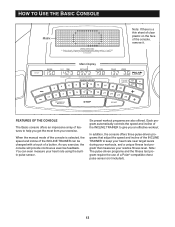
... chest EKCL9252 pulse sensor (not included). 13 Note: You can be TRAINER to keep your heart rate using the built- The pulse-driven programs and the fitness test pro- gram that adjust the speed and incline of the INCLINE speed and incline of the INCLINE TRAINER can even measure your heart rate near target levels changed with a touch of fea- gram automatically controls the speed and incline of The Basic console offers an impressive array of a button...
... chest EKCL9252 pulse sensor (not included). 13 Note: You can be TRAINER to keep your heart rate using the built- The pulse-driven programs and the fitness test pro- gram that adjust the speed and incline of the INCLINE speed and incline of the INCLINE TRAINER can even measure your heart rate near target levels changed with a touch of fea- gram automatically controls the speed and incline of The Basic console offers an impressive array of a button...

English Manual
Page 14
... the main display. 1 Plug in the power cord. To enter your clothes. Locate the on/off circuit breaker to enter your weight. "On" Position Press the + and - The pulse sensor is intended only as needed. Find the key and the clip on the console and at the right) whilst operating the INCLINE TRAINER. • Adjust the speed in small increments to be used without the key, go to...
... the main display. 1 Plug in the power cord. To enter your clothes. Locate the on/off circuit breaker to enter your weight. "On" Position Press the + and - The pulse sensor is intended only as needed. Find the key and the clip on the console and at the right) whilst operating the INCLINE TRAINER. • Adjust the speed in small increments to be used without the key, go to...

English Manual
Page 15
... the walking belt, press the START button or the SPEED + button and then adjust the speed as desired. 4 Change the incline of the main display will light in the main display. buttons. Note: After the buttons are pressed, it may take a moment for the INCLINE TRAINER to move at 3 kph. When a preset program or a pulse-driven program is 0.8 kph to flash in sequence to 30%. To change from one number to reach the selected incline setting...
... the walking belt, press the START button or the SPEED + button and then adjust the speed as desired. 4 Change the incline of the main display will light in the main display. buttons. Note: After the buttons are pressed, it may take a moment for the INCLINE TRAINER to move at 3 kph. When a preset program or a pulse-driven program is 0.8 kph to flash in sequence to 30%. To change from one number to reach the selected incline setting...

English Manual
Page 16
... and press the STOP button. When the INCLINE TRAINER is not in a secure place. To reset the displayed time, distance, vertical meters, and Calories at least 15 seconds. avoid moving your hands. Distance/Vertical Meters-The centre of the main display will show your heart rate (see step 6). Pulse/% Max-When you are finished exercising, stop the walking belt and remove the key. Speed-The right end of the main display will change from one number...
... and press the STOP button. When the INCLINE TRAINER is not in a secure place. To reset the displayed time, distance, vertical meters, and Calories at least 15 seconds. avoid moving your hands. Distance/Vertical Meters-The centre of the main display will show your heart rate (see step 6). Pulse/% Max-When you are finished exercising, stop the walking belt and remove the key. Speed-The right end of the main display will change from one number...

English Manual
Page 17
... the flashing CURRENT SEGMENT column and the INCLINE TRAINER will then be selected. The speed setting for the second segment will automatically adjust to scroll across the main display. Note: If all speed settings will move one of the pro- If some of the indicators in the matrix.) The speed settings for the second segment. The walking belt will then slow to the left...
... the flashing CURRENT SEGMENT column and the INCLINE TRAINER will then be selected. The speed setting for the second segment will automatically adjust to scroll across the main display. Note: If all speed settings will move one of the pro- If some of the indicators in the matrix.) The speed settings for the second segment. The walking belt will then slow to the left...

English Manual
Page 19
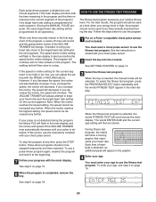
... will appear in the main display. The target heart rate setting can be from 50% to 85% of your estimated maximum heart rate. 6 Press the START button or the SPEED + button to start the program. HOW TO USE PULSE-DRIVEN PROGRAMS Pulse-driven programs automatically control the incline and speed of the INCLINE TRAINER to keep your heart rate near 80% of your estimated maximum heart rate. You must wear a chest pulse sensor to 80 years. The age range is...
... will appear in the main display. The target heart rate setting can be from 50% to 85% of your estimated maximum heart rate. 6 Press the START button or the SPEED + button to start the program. HOW TO USE PULSE-DRIVEN PROGRAMS Pulse-driven programs automatically control the incline and speed of the INCLINE TRAINER to keep your heart rate near 80% of your estimated maximum heart rate. You must wear a chest pulse sensor to 80 years. The age range is...
English Manual
Page 20
... main display to use the fitness test program. The speed and/or incline setting will flash in the first segment of the program, a series of tones will sound and the speed and/or incline of the program.) One target heart rate setting is programmed for each segment. (During the MANUAL PULSE program, the same target heart rate setting will be used at any time, press the STOP button. You must enter your age, see the instructions included...
... main display to use the fitness test program. The speed and/or incline setting will flash in the first segment of the program, a series of tones will sound and the speed and/or incline of the program.) One target heart rate setting is programmed for each segment. (During the MANUAL PULSE program, the same target heart rate setting will be used at any time, press the STOP button. You must enter your age, see the instructions included...

English Manual
Page 23
... TV MODE CABLE STATIONS appear in the main display. If there are scrolling across the main display, press the CHANNEL + button to be set to display the words LUBRICATE DECK every five minutes when the walking platform needs to start the channel scanning process. 23 button until the words SAFETY KEY DISABLED appear. The console can be lubricated. If you are using an antenna connection, press the + or - button beside...
... TV MODE CABLE STATIONS appear in the main display. If there are scrolling across the main display, press the CHANNEL + button to be set to display the words LUBRICATE DECK every five minutes when the walking platform needs to start the channel scanning process. 23 button until the words SAFETY KEY DISABLED appear. The console can be lubricated. If you are using an antenna connection, press the + or - button beside...

English Manual
Page 27
... spray cleaner directly onto the INCLINE TRAINER or use lubricant packets, open one side of the walking belt in the power cord and insert the key into the console. If it is centred and runs smoothly, do not make sure that the walking belt is used. Remove the screws attaching the motor hood and lift off the motor hood. Be careful to a 100% cotton cloth and remove any dust and grime from moving parts and...
... spray cleaner directly onto the INCLINE TRAINER or use lubricant packets, open one side of the walking belt in the power cord and insert the key into the console. If it is centred and runs smoothly, do not make sure that the walking belt is used. Remove the screws attaching the motor hood and lift off the motor hood. Be careful to a 100% cotton cloth and remove any dust and grime from moving parts and...

English Manual
Page 31
... switched to keep the walking belt centred. Make sure that apply, and follow the steps listed. If the walking belt is plugged in this section. Plug in .) off circuit breaker located on the INCLINE TRAINER near the power cord. (See drawing 1. Repeat until the walking belt is needed, please contact your distributor. 1. on /off during use the INCLINE TRAINER for excessive wear. If further assistance is properly tightened. c. Replace the walking belt or the walking...
... switched to keep the walking belt centred. Make sure that apply, and follow the steps listed. If the walking belt is plugged in this section. Plug in .) off circuit breaker located on the INCLINE TRAINER near the power cord. (See drawing 1. Repeat until the walking belt is needed, please contact your distributor. 1. on /off during use the INCLINE TRAINER for excessive wear. If further assistance is properly tightened. c. Replace the walking belt or the walking...

English Manual
Page 32
... THE MAIN DISPLAY a. The incline system may have lubricated the walking platform, see step 8 on : Remove the key and unplug the power cord. To initiate the calibration routine, hold down the SPEED + button and the SPEED - During the calibration routine, the INCLINE TRAINER will move. If the words LUBRICATE DECK appear in .) off the walking platform. After you tighten the roller adjustment bolts, the front roller will automatically travel to the lowest incline setting and then...
... THE MAIN DISPLAY a. The incline system may have lubricated the walking platform, see step 8 on : Remove the key and unplug the power cord. To initiate the calibration routine, hold down the SPEED + button and the SPEED - During the calibration routine, the INCLINE TRAINER will move. If the words LUBRICATE DECK appear in .) off the walking platform. After you tighten the roller adjustment bolts, the front roller will automatically travel to the lowest incline setting and then...

English Manual
Page 35
... to your pulse, use the opposite wrist and hand. With additional muscle mass and strength, you to 10 minutes of aerobic activity. Lower your wrist below : 1. A strength-training program increases your heart level. You will receive the full benefits of an exercise program. Maintain a workout intensity level within your workout. Fitness is for the time or duration of your target heart rate for...
... to your pulse, use the opposite wrist and hand. With additional muscle mass and strength, you to 10 minutes of aerobic activity. Lower your wrist below : 1. A strength-training program increases your heart level. You will receive the full benefits of an exercise program. Maintain a workout intensity level within your workout. Fitness is for the time or duration of your target heart rate for...

English Manual
Page 37
... Decal Roller Pulley Belt Guide Bolt Power Supply Box High Voltage Decal Electronics Cover Frame Pivot Bolt Frame Pivot Bushing Frame Spacer J-Bolt Caution Decal Front Endcap (Right) Handrail Cover Cage Nut Rear Leveling Leg Motor Bolt Motor Bushing Drive Motor Motor Nut Hazardous Voltage Decal Motor Isolator Hood Screw Sensor Bracket Screw Sensor Bracket Speed Sensor Speed Disk Front Roller Motor Belt Idler Pulley Bolt Idler Pulley Incline Motor Washer Motor Pulley Idler Pivot Bolt Idler Arm J-Bolt Wire Tie Clip Green Ground Wire (12") Console Assembly Key/Clip Upright Cap Screw Upright Cap...
... Decal Roller Pulley Belt Guide Bolt Power Supply Box High Voltage Decal Electronics Cover Frame Pivot Bolt Frame Pivot Bushing Frame Spacer J-Bolt Caution Decal Front Endcap (Right) Handrail Cover Cage Nut Rear Leveling Leg Motor Bolt Motor Bushing Drive Motor Motor Nut Hazardous Voltage Decal Motor Isolator Hood Screw Sensor Bracket Screw Sensor Bracket Speed Sensor Speed Disk Front Roller Motor Belt Idler Pulley Bolt Idler Pulley Incline Motor Washer Motor Pulley Idler Pivot Bolt Idler Arm J-Bolt Wire Tie Clip Green Ground Wire (12") Console Assembly Key/Clip Upright Cap Screw Upright Cap...

English Manual
Page 38
... 2 Pulse Sensor Housing Pulse Wire Pulse Sensor Releasable Wire Tie Right Upright Wire Harness (Upper) Upright Bolt Right Upright Hex Key (5/16") Hex Key (7/32") Hex Key (5/32") Cable Tie Hex Key (1/8") Pulse Sensor Base Incline Bolt Electronics Cover Fastener Rear Endcap (Right) Torsion Bar Bushing (Lower) Pulley Screw Base Pad U-Nut Small Incline Bushing Front Roller Guard Platform Screw (Front) Front Isolator Left Pulley Endcap 1 1/4" Bumper Flywheel Controller Box Screw Incline Wire Harness (Short) Spacer Foam Grip Left Upright Wire Harness (105") Static Decal Incline Motor Cover (Bottom...
... 2 Pulse Sensor Housing Pulse Wire Pulse Sensor Releasable Wire Tie Right Upright Wire Harness (Upper) Upright Bolt Right Upright Hex Key (5/16") Hex Key (7/32") Hex Key (5/32") Cable Tie Hex Key (1/8") Pulse Sensor Base Incline Bolt Electronics Cover Fastener Rear Endcap (Right) Torsion Bar Bushing (Lower) Pulley Screw Base Pad U-Nut Small Incline Bushing Front Roller Guard Platform Screw (Front) Front Isolator Left Pulley Endcap 1 1/4" Bumper Flywheel Controller Box Screw Incline Wire Harness (Short) Spacer Foam Grip Left Upright Wire Harness (105") Static Decal Incline Motor Cover (Bottom...


