GS716Tv2/GS724Tv3 Hardware manual
Page 2
... in the BMPTAmtsblVfg 243/1991 and Vfg 46/1992. Trademarks NETGEAR, the NETGEAR logo, and Auto Uplink are copyright Intoto, Inc. NETGEAR does not assume any liability that the Smart Switch has been suppressed in accordance with the regulations. Statement of ... In the interest of NETGEAR, Inc. Product and Publication Details Model Number: Publication Date: Product Family: Product Name: Home or Business Product: Language: Publication Part Number: Publication Version Number: GS716T and GS724T June 2009 GS716T/GS724T Series Smart Switch Smart Switch Business English 202-10510...
... in the BMPTAmtsblVfg 243/1991 and Vfg 46/1992. Trademarks NETGEAR, the NETGEAR logo, and Auto Uplink are copyright Intoto, Inc. NETGEAR does not assume any liability that the Smart Switch has been suppressed in accordance with the regulations. Statement of ... In the interest of NETGEAR, Inc. Product and Publication Details Model Number: Publication Date: Product Family: Product Name: Home or Business Product: Language: Publication Part Number: Publication Version Number: GS716T and GS724T June 2009 GS716T/GS724T Series Smart Switch Smart Switch Business English 202-10510...
GS716Tv2/GS724Tv3 Hardware manual
Page 3
...Formats and Scope v Revision History ...vi Chapter 1 Introduction Overview ...1-1 Features ...1-2 Package Contents ...1-3 Chapter 2 Physical Description GS716T Front and Back Panel Configuration 2-5 GS724T Front and Back Panel Configuration 2-6 LED Designations ...2-7 Port LEDs ...2-7 System LEDs... SFP GBIC Module ...2-9 Factory Defaults Button 2-9 Chapter 3 Applications Desktop Switching ...3-11 Chapter 4 Installation Step 1: Preparing the Site 4-13 Step 2: Installing the Switch 4-14 Installing the Switch on a Flat Surface 4-14 Installing the Switch in a Rack 4-14 iii v1.0, June 2009
...Formats and Scope v Revision History ...vi Chapter 1 Introduction Overview ...1-1 Features ...1-2 Package Contents ...1-3 Chapter 2 Physical Description GS716T Front and Back Panel Configuration 2-5 GS724T Front and Back Panel Configuration 2-6 LED Designations ...2-7 Port LEDs ...2-7 System LEDs... SFP GBIC Module ...2-9 Factory Defaults Button 2-9 Chapter 3 Applications Desktop Switching ...3-11 Chapter 4 Installation Step 1: Preparing the Site 4-13 Step 2: Installing the Switch 4-14 Installing the Switch on a Flat Surface 4-14 Installing the Switch in a Rack 4-14 iii v1.0, June 2009
GS716Tv2/GS724Tv3 Hardware manual
Page 4
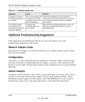
GS716T/GS724T Hardware Installation Guide Step 3: Checking the Installation 4-15 Step 4: Connecting Devices to the Switch 4-16 Step 5: Installing an SFP GBIC Module 4-16 Step 6: Applying AC Power 4-17 Step 7: Managing the Switch using a Web Browser or the PC Utility 4-18 Appendix A Troubleshooting Troubleshooting Chart A-19 Additional Troubleshooting Suggestions A-20 Network Adapter Cards A-20 Configuration ...A-20 Switch Integrity ...A-20 Auto-Negotiation A-21 Appendix B Technical Specifications Index iv v1.0, June 2009
GS716T/GS724T Hardware Installation Guide Step 3: Checking the Installation 4-15 Step 4: Connecting Devices to the Switch 4-16 Step 5: Installing an SFP GBIC Module 4-16 Step 6: Applying AC Power 4-17 Step 7: Managing the Switch using a Web Browser or the PC Utility 4-18 Appendix A Troubleshooting Troubleshooting Chart A-19 Additional Troubleshooting Suggestions A-20 Network Adapter Cards A-20 Configuration ...A-20 Switch Integrity ...A-20 Auto-Negotiation A-21 Appendix B Technical Specifications Index iv v1.0, June 2009

GS716Tv2/GS724Tv3 Hardware manual
Page 5
About This Manual The NETGEAR® ProSafeTM GS716T/GS724T Hardware Installation Guide describes how to highlight information of importance or special interest. This manual uses the following paragraphs: • Typographical Conventions. Conventions, Formats ... addresses, GUI screen text Command prompt, CLI text, code URL links • Formats. Tip: This format is used to install, configure and troubleshoot the Smart Switch. v v1.0, June 2009
About This Manual The NETGEAR® ProSafeTM GS716T/GS724T Hardware Installation Guide describes how to highlight information of importance or special interest. This manual uses the following paragraphs: • Typographical Conventions. Conventions, Formats ... addresses, GUI screen text Command prompt, CLI text, code URL links • Formats. Tip: This format is used to install, configure and troubleshoot the Smart Switch. v v1.0, June 2009
GS716Tv2/GS724Tv3 Hardware manual
Page 6
Revision History Part Number Version Number Date 202-10510-01 1.0 June 2009 Description Initial release vi v1.0, June 2009 website at http://kbserver.netgear.com/main.asp. This manual is a safety warning. Failure to these specifications: Product Version Manual Publication Date Smart Switch June 2009 Note: Product updates are available on the NETGEAR, Inc. GS716T/GS724T Hardware Installation Guide Danger: This is written for the Smart Switch according to take heed of this notice may result in personal injury or death. • Scope.
Revision History Part Number Version Number Date 202-10510-01 1.0 June 2009 Description Initial release vi v1.0, June 2009 website at http://kbserver.netgear.com/main.asp. This manual is a safety warning. Failure to these specifications: Product Version Manual Publication Date Smart Switch June 2009 Note: Product updates are available on the NETGEAR, Inc. GS716T/GS724T Hardware Installation Guide Danger: This is written for the Smart Switch according to take heed of this notice may result in personal injury or death. • Scope.
GS716Tv2/GS724Tv3 Hardware manual
Page 7
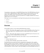
...SX/LX)/100 Mbps SFP. This product offers support for 24 ports of 1-1 v1.0, June 2009 The NETGEAR Smart Switch is for use out of the NETGEAR Smart Switch. The switch's management features include configuration for port and switch information, VLAN for traffic control, port trunking for users who require a large number of ports and ...100 Mbps Small Form-factor Pluggable (SFP). • GS724T - Chapter 1 Introduction Congratulations on the purchase of the box. For example: • Linking to the Smart Switch and provides the following NETGEAR Smart Switches: • GS716T -
...SX/LX)/100 Mbps SFP. This product offers support for 24 ports of 1-1 v1.0, June 2009 The NETGEAR Smart Switch is for use out of the NETGEAR Smart Switch. The switch's management features include configuration for port and switch information, VLAN for traffic control, port trunking for users who require a large number of ports and ...100 Mbps Small Form-factor Pluggable (SFP). • GS724T - Chapter 1 Introduction Congratulations on the purchase of the box. For example: • Linking to the Smart Switch and provides the following NETGEAR Smart Switches: • GS716T -
GS716Tv2/GS724Tv3 Hardware manual
Page 8
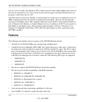
...taking priority if both devices are supported: • 1000BASE-SX • 1000BASE-LX • 100BASE-FX • The devices support full NETGEAR Smart Switch functionality. • The devices provide full compatibility with IEEE standards: • IEEE 802.3i, (10BASE-T) • IEEE 802.3u (... that have a mix of Ethernet, Fast Ethernet, or Gigabit Ethernet devices. GS716T/GS724T Hardware Installation Guide Service (CoS) for environments that runs on each device. This capability makes the switch ideal for traffic prioritization. In addition, all ports to the Combo ports are...
...taking priority if both devices are supported: • 1000BASE-SX • 1000BASE-LX • 100BASE-FX • The devices support full NETGEAR Smart Switch functionality. • The devices provide full compatibility with IEEE standards: • IEEE 802.3i, (10BASE-T) • IEEE 802.3u (... that have a mix of Ethernet, Fast Ethernet, or Gigabit Ethernet devices. GS716T/GS724T Hardware Installation Guide Service (CoS) for environments that runs on each device. This capability makes the switch ideal for traffic prioritization. In addition, all ports to the Combo ports are...
GS716Tv2/GS724Tv3 Hardware manual
Page 9
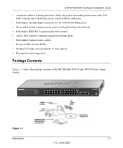
...802.3x pause frame flow control. • Active flow control to build the packet-forwarding information table. GS716T/GS724T Hardware Installation Guide • Automatic address learning function to minimize packet loss/frame drops. • Half.... • Standard 1U high, rack-mountable 17-inch chassis. • Fan speed control supported. Reset PWR ® ProSafe 24 Port Gigabit Smart Switch 1 3 5 7 9 11 13 15 17 19 21 23 LINK/ACT SPD Green (1000M) Yellow (100M) FDX ... 2009 Package Contents Figure 1-1 shows the package contents of the NETGEAR GS716T and GS724T Series Smart Switch.
...802.3x pause frame flow control. • Active flow control to build the packet-forwarding information table. GS716T/GS724T Hardware Installation Guide • Automatic address learning function to minimize packet loss/frame drops. • Half.... • Standard 1U high, rack-mountable 17-inch chassis. • Fan speed control supported. Reset PWR ® ProSafe 24 Port Gigabit Smart Switch 1 3 5 7 9 11 13 15 17 19 21 23 LINK/ACT SPD Green (1000M) Yellow (100M) FDX ... 2009 Package Contents Figure 1-1 shows the package contents of the NETGEAR GS716T and GS724T Series Smart Switch.
GS716Tv2/GS724Tv3 Hardware manual
Page 10
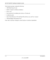
GS716T/GS724T Hardware Installation Guide Verify that the package contains the following: • NETGEAR Smart Switch • Rubber footpads for tabletop installation • Power cord • Rack-mount kit for installing the switch in a 19-inch rack • Installation guide • Smart Switch Resource CD with Smart Wizard Discovery and User's manual • Warranty/Support Information Card If any item is missing or damaged, contact the place of purchase immediately. 1-4 Introduction v1.0, June 2009
GS716T/GS724T Hardware Installation Guide Verify that the package contains the following: • NETGEAR Smart Switch • Rubber footpads for tabletop installation • Power cord • Rack-mount kit for installing the switch in a 19-inch rack • Installation guide • Smart Switch Resource CD with Smart Wizard Discovery and User's manual • Warranty/Support Information Card If any item is missing or damaged, contact the place of purchase immediately. 1-4 Introduction v1.0, June 2009

GS716Tv2/GS724Tv3 Hardware manual
Page 11
... of sensing the line speed and negotiating the operation duplex mode with the link partner automatically Figure 2-1 illustrates the NETGEAR GS716T Smart Switch front panel: System LEDs Reset PWR ® ProSafe 16 Port Gigabit Smart Switch 1 3 5 7 9 11 13 15 LINK/ACT SPD Green (1000M) Yellow (100M) FDX 2 4 6 8 ...10 12 14 16 LINK/ACT SPD FDX 1 3 5 7 2 4 6 8 9 11 13 15T 10 12 14 16T 15F 16F Link/ Link/ ACT ACT MODEL GS716T Auto™ Uplink Factory...
... of sensing the line speed and negotiating the operation duplex mode with the link partner automatically Figure 2-1 illustrates the NETGEAR GS716T Smart Switch front panel: System LEDs Reset PWR ® ProSafe 16 Port Gigabit Smart Switch 1 3 5 7 9 11 13 15 LINK/ACT SPD Green (1000M) Yellow (100M) FDX 2 4 6 8 ...10 12 14 16 LINK/ACT SPD FDX 1 3 5 7 2 4 6 8 9 11 13 15T 10 12 14 16T 15F 16F Link/ Link/ ACT ACT MODEL GS716T Auto™ Uplink Factory...
GS716Tv2/GS724Tv3 Hardware manual
Page 12
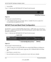
...sensing the line speed and negotiating the operation duplex mode with the link partner automatically Figure 2-3 illustrates the NETGEAR GS724T Smart Switch front panel: System LEDs Reset PWR ® ProSafe 24 Port Gigabit Smart Switch 1 3 5 7 9 11 13 15 17 19 21 23 LINK/ACT SPD Green (1000M) Yellow....0, June 2009 Every RJ-45 port is a 24-port 10/100/1000 Mbps Smart Switch + 2 SFP Combo ports switch. GS716T/GS724T Hardware Installation Guide • System LEDs Figure 2-2 illustrates the NETGEAR GS716T Smart Switch back panel: 100-240V ~ 50-60Hz Figure 2-2 RS-232 Power Connector The back ...
...sensing the line speed and negotiating the operation duplex mode with the link partner automatically Figure 2-3 illustrates the NETGEAR GS724T Smart Switch front panel: System LEDs Reset PWR ® ProSafe 24 Port Gigabit Smart Switch 1 3 5 7 9 11 13 15 17 19 21 23 LINK/ACT SPD Green (1000M) Yellow....0, June 2009 Every RJ-45 port is a 24-port 10/100/1000 Mbps Smart Switch + 2 SFP Combo ports switch. GS716T/GS724T Hardware Installation Guide • System LEDs Figure 2-2 illustrates the NETGEAR GS716T Smart Switch back panel: 100-240V ~ 50-60Hz Figure 2-2 RS-232 Power Connector The back ...
GS716Tv2/GS724Tv3 Hardware manual
Page 13
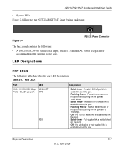
A valid 1000 Mbps link is a standard AC power receptacle for accommodating the supplied power cord. GS716T/GS724T Hardware Installation Guide • System LEDs Figure 2-4 illustrates the NETGEAR GS724T Smart Switch back panel: Figure 2-4 100-240V ~ 50-60Hz RS-232 Power Connector The back panel contains the following table describes the port LED designations. No...
A valid 1000 Mbps link is a standard AC power receptacle for accommodating the supplied power cord. GS716T/GS724T Hardware Installation Guide • System LEDs Figure 2-4 illustrates the NETGEAR GS724T Smart Switch back panel: Figure 2-4 100-240V ~ 50-60Hz RS-232 Power Connector The back panel contains the following table describes the port LED designations. No...
GS716Tv2/GS724Tv3 Hardware manual
Page 14
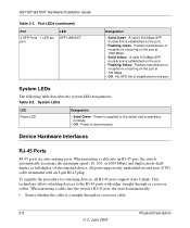
...port. Packets transmission or reception is a straight-through or crossover cables. When inserting a cable into an RJ-45 port, the switch automatically ascertains the maximum speed (10, 100, or 1000 Mbps) and duplex mode (halfduplex or full-duplex) of the attached ...device. System LEDs The following table describes the system LED designations. Table 2-2. GS716T/GS724T Hardware Installation Guide Table 2-1. When inserting a cable into the switch's RJ-45 port, the switch automatically: • Senses whether the cable is occurring on the port. • Flashing ...
...port. Packets transmission or reception is a straight-through or crossover cables. When inserting a cable into an RJ-45 port, the switch automatically ascertains the maximum speed (10, 100, or 1000 Mbps) and duplex mode (halfduplex or full-duplex) of the attached ...device. System LEDs The following table describes the system LED designations. Table 2-2. GS716T/GS724T Hardware Installation Guide Table 2-1. When inserting a cable into the switch's RJ-45 port, the switch automatically: • Senses whether the cable is occurring on the port. • Flashing ...
GS716Tv2/GS724Tv3 Hardware manual
Page 15
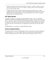
GS716T/GS724T Hardware Installation Guide • Determines whether the link to the attached device requires a "normal" connection (such as when connecting the port to a PC) or an "uplink" connection (such as the AGM731F, AGM732F, or AGM733 from NETGEAR, allowing fiber connections on the network. The module ... June 2009 SFP GBIC Module The GBIC module bays accommodate standard SFP GBIC modules, such as when connecting the port to a router, switch, or hub). • Configures the RJ-45 port to use crossover or straightthrough cables when attaching devices. The SFP GBIC bay accommodates...
GS716T/GS724T Hardware Installation Guide • Determines whether the link to the attached device requires a "normal" connection (such as when connecting the port to a PC) or an "uplink" connection (such as the AGM731F, AGM732F, or AGM733 from NETGEAR, allowing fiber connections on the network. The module ... June 2009 SFP GBIC Module The GBIC module bays accommodate standard SFP GBIC modules, such as when connecting the port to a router, switch, or hub). • Configures the RJ-45 port to use crossover or straightthrough cables when attaching devices. The SFP GBIC bay accommodates...
GS716Tv2/GS724Tv3 Hardware manual
Page 18
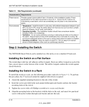
... electromagnetic noise, such as direct sunlight, warm air exhausts, hot-air vents, and heaters. • Operating humidity - GS716T/GS724T Hardware Installation Guide Table 4-1. Step 2: Installing the Switch The NETGEAR Smart Switch can accidentally turn off power to the side of the switch. Keep at least 6 ft. (1.83 m) away from heat sources such as a photocopy machine.
... electromagnetic noise, such as direct sunlight, warm air exhausts, hot-air vents, and heaters. • Operating humidity - GS716T/GS724T Hardware Installation Guide Table 4-1. Step 2: Installing the Switch The NETGEAR Smart Switch can accidentally turn off power to the side of the switch. Keep at least 6 ft. (1.83 m) away from heat sources such as a photocopy machine.
GS716Tv2/GS724Tv3 Hardware manual
Page 19
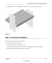
Figure 4-1 Step 3: Checking the Installation Before applying power perform the following: • Inspect the equipment thoroughly. • Verify that all cables are not damaged or creating a safety hazard. • Ensure all equipment is mounted properly and securely. GS716T/GS724T Hardware Installation Guide 5. Tighten the screws with a #2 Phillips screwdriver to make sure cables are installed correctly. • Check cable routing to secure the switch in the rack. Installation v1.0, June 2009 4-15
Figure 4-1 Step 3: Checking the Installation Before applying power perform the following: • Inspect the equipment thoroughly. • Verify that all cables are not damaged or creating a safety hazard. • Ensure all equipment is mounted properly and securely. GS716T/GS724T Hardware Installation Guide 5. Tighten the screws with a #2 Phillips screwdriver to make sure cables are installed correctly. • Check cable routing to secure the switch in the rack. Installation v1.0, June 2009 4-15

GS716Tv2/GS724Tv3 Hardware manual
Page 20
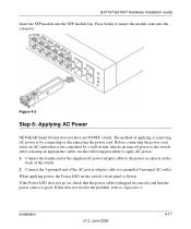
GS716T/GS724T Hardware Installation Guide Step 4: Connecting Devices to the Switch The following procedure describes how to the switch's RJ-45 ports. The NETGEAR Smart Switch contains Auto Uplink™ technology, which allows the attaching of devices using either straight-through or crossover cables. Step 5: Installing an SFP GBIC Module The ...
GS716T/GS724T Hardware Installation Guide Step 4: Connecting Devices to the Switch The following procedure describes how to the switch's RJ-45 ports. The NETGEAR Smart Switch contains Auto Uplink™ technology, which allows the attaching of devices using either straight-through or crossover cables. Step 5: Installing an SFP GBIC Module The ...
GS716Tv2/GS724Tv3 Hardware manual
Page 21
...power adapter cable to apply AC power. 1. Figure 4-3 Step 6: Applying AC Power NETGEAR Smart Switch does not have an ON/OFF switch. If the Power LED does not go on the switch's front panel is by a wall switch, which can turn off power to Appendix A . Installation v1.0, June 2009 4-...17 After selecting an appropriate outlet, use the following procedure to a grounded 3-pronged AC outlet. GS716T/GS724T Hardware Installation Guide Insert the ...
...power adapter cable to apply AC power. 1. Figure 4-3 Step 6: Applying AC Power NETGEAR Smart Switch does not have an ON/OFF switch. If the Power LED does not go on the switch's front panel is by a wall switch, which can turn off power to Appendix A . Installation v1.0, June 2009 4-...17 After selecting an appropriate outlet, use the following procedure to a grounded 3-pronged AC outlet. GS716T/GS724T Hardware Installation Guide Insert the ...

GS716Tv2/GS724Tv3 Hardware manual
Page 22
... switch for the first time, the Smart Switch can be configured using a Web browser or a utility program called SmartWizard Discovery. GS716T/GS724T Hardware Installation Guide Step 7: Managing the Switch... using the management software. However, the management software enables the setup of VLAN and Trunking features, and also improves the efficiency of the switch...This management software is a default IP address already configured on the Smart Switch Resource CD. The default IP address is 192.168.0.239 and subnet mask...
... switch for the first time, the Smart Switch can be configured using a Web browser or a utility program called SmartWizard Discovery. GS716T/GS724T Hardware Installation Guide Step 7: Managing the Switch... using the management software. However, the management software enables the setup of VLAN and Trunking features, and also improves the efficiency of the switch...This management software is a default IP address already configured on the Smart Switch Resource CD. The default IP address is 192.168.0.239 and subnet mask...
GS716Tv2/GS724Tv3 Hardware manual
Page 24
...A-20 v1.0, June 2009 Troubleshooting Equipment may have been accidentally disconnected. Switch Integrity If required, verify the integrity of the network. A network loop (redundant path) has been created. GS716T/GS724T Hardware Installation Guide Table A-1. ACT LED is only one step at... a time. In North America, call 1-888-NETGEAR. If the problem continues, contact NETGEAR technical support. Ensure all connected ports and the ...
...A-20 v1.0, June 2009 Troubleshooting Equipment may have been accidentally disconnected. Switch Integrity If required, verify the integrity of the network. A network loop (redundant path) has been created. GS716T/GS724T Hardware Installation Guide Table A-1. ACT LED is only one step at... a time. In North America, call 1-888-NETGEAR. If the problem continues, contact NETGEAR technical support. Ensure all connected ports and the ...


