
FS726T User Manual
Page 4
....1Q Tag VLAN 3-7 Switch> Trunking Page 3-9 Switch> Monitor Page 3-10 Switch> Advanced> Jumbo Frame 3-10 Switch> Advanced> Spanning Tree Page 3-11 Switch> Advanced> SNMP 3-11 Firmware Menu ...3-12 Firmware> Configuration Backup Page 3-12 Firmware> Factory Reset Page 3-12 Logout ...3-13 Chapter 5 Software Upgrade Appendix A Default Settings Appendix B IEEE 802.1Q Virtual Local Area Network (VLAN) IEEE...
....1Q Tag VLAN 3-7 Switch> Trunking Page 3-9 Switch> Monitor Page 3-10 Switch> Advanced> Jumbo Frame 3-10 Switch> Advanced> Spanning Tree Page 3-11 Switch> Advanced> SNMP 3-11 Firmware Menu ...3-12 Firmware> Configuration Backup Page 3-12 Firmware> Factory Reset Page 3-12 Logout ...3-13 Chapter 5 Software Upgrade Appendix A Default Settings Appendix B IEEE 802.1Q Virtual Local Area Network (VLAN) IEEE...
FS726T User Manual
Page 16
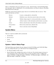
...10M Full), 100 Mbps half duplex (100M Half), 100 Mbps full duplex (100M Full), or Disable. 4-2 Web-Based Management Interface July 2005 Smart Switch Series Software Manual There is a Help button. The possible entries are 4 options available in the top of right side of the Help Menu that ...new entries to read the full Help Menu. Within the various browser interface pages, there are below: Browse: Refresh: Apply: Add: Delete: Factory Reset: Help: Locates a certain path for both 10/100 Mbps and 10/100/1000 Mbps ports. If you click that screen's data from table and...
...10M Full), 100 Mbps half duplex (100M Half), 100 Mbps full duplex (100M Full), or Disable. 4-2 Web-Based Management Interface July 2005 Smart Switch Series Software Manual There is a Help button. The possible entries are 4 options available in the top of right side of the Help Menu that ...new entries to read the full Help Menu. Within the various browser interface pages, there are below: Browse: Refresh: Apply: Add: Delete: Factory Reset: Help: Locates a certain path for both 10/100 Mbps and 10/100/1000 Mbps ports. If you click that screen's data from table and...

FS726T User Manual
Page 27
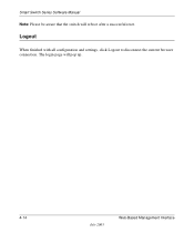
...reboot after a successful restore. Note: The Backup file does not affect the password and MAC address of the switch Firmware> Factory Reset Page You can always reset the switch to default values by using a duplicate configuration): • Click Restore to recover the Backup file from your ...available: • Configuration Backup • Factory Reset Firmware> Configuration Backup Page You can backup the system and switch settings to your PC to the current switch. If you own several switches and you can use this function • When reset process is finished, click OK to confirm ...
...reboot after a successful restore. Note: The Backup file does not affect the password and MAC address of the switch Firmware> Factory Reset Page You can always reset the switch to default values by using a duplicate configuration): • Click Restore to recover the Backup file from your ...available: • Configuration Backup • Factory Reset Firmware> Configuration Backup Page You can backup the system and switch settings to your PC to the current switch. If you own several switches and you can use this function • When reset process is finished, click OK to confirm ...
FS726T User Manual
Page 28
Logout When finished with all configuration and settings, click Logout to disconnect the current browser connection. Smart Switch Series Software Manual Note: Please be aware that the switch will pop up. 4-14 July 2005 Web-Based Management Interface The login page will reboot after a successful reset.
Logout When finished with all configuration and settings, click Logout to disconnect the current browser connection. Smart Switch Series Software Manual Note: Please be aware that the switch will pop up. 4-14 July 2005 Web-Based Management Interface The login page will reboot after a successful reset.
FS726T User Manual
Page 45
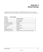
You can always configure the switch to default settings by using the Factory Reset function from a Web browser. Default Settings FEATURE Port Speed Port Duplex Flow Control (half duplex) Flow Control (full duplex) IP ...Configuration Password VLAN Link Aggregation (Trunk) Traffic Prioritization (QoS) DEFAULT SETTING Auto-negotiation Auto-negotiation Enabled Enabled DHCP enabled password Port-Based VLAN Disabled Optimized for the NETGEAR Smart Switches...
You can always configure the switch to default settings by using the Factory Reset function from a Web browser. Default Settings FEATURE Port Speed Port Duplex Flow Control (half duplex) Flow Control (full duplex) IP ...Configuration Password VLAN Link Aggregation (Trunk) Traffic Prioritization (QoS) DEFAULT SETTING Auto-negotiation Auto-negotiation Enabled Enabled DHCP enabled password Port-Based VLAN Disabled Optimized for the NETGEAR Smart Switches...
FS726T User Manual
Page 47
... 5-29 CLI Configure System IP-Mode 5-29 CLI Configure System Mask 5-29 CLI Configure System Password 5-31 CLI Configure System RADIUS 5-32 CLI Configure System Reset 5-33 1
... 5-29 CLI Configure System IP-Mode 5-29 CLI Configure System Mask 5-29 CLI Configure System Password 5-31 CLI Configure System RADIUS 5-32 CLI Configure System Reset 5-33 1
FS726T User Manual
Page 48
CLI Configure System Restore 5-30 CLI Configure System Save 5-30 CLI Configure System Stat-Reset 5-34 CLI Configure System Username 5-31 CLI Configure System Web 5-30 CLI Configure Trap 5-25 CLI Exit 5-3 CLI Help 5-2 CLI ... CMI 3-3 COM Port Selection 3-2 Command Menu Interface 3-3 Configuration Manager 4-30 console port 3-1 conventions typography 1-2 Cost 3-25, 4-37 crossover cable D-2 2 D Device Reset 4-18 Differentiated Service 3-20 Differentiated Service Code Points 3-20 DiffServ 3-20 Direct Console Access 3-1 Disable Advanced Alerting 4-20, 4-22 Documentation updates 1-2 DSCP 3-20 E Enable...
CLI Configure System Restore 5-30 CLI Configure System Save 5-30 CLI Configure System Stat-Reset 5-34 CLI Configure System Username 5-31 CLI Configure System Web 5-30 CLI Configure Trap 5-25 CLI Exit 5-3 CLI Help 5-2 CLI ... CMI 3-3 COM Port Selection 3-2 Command Menu Interface 3-3 Configuration Manager 4-30 console port 3-1 conventions typography 1-2 Cost 3-25, 4-37 crossover cable D-2 2 D Device Reset 4-18 Differentiated Service 3-20 Differentiated Service Code Points 3-20 DiffServ 3-20 Direct Console Access 3-1 Disable Advanced Alerting 4-20, 4-22 Documentation updates 1-2 DSCP 3-20 E Enable...
GS716Tv2/GS724Tv3 Hardware manual
Page 9
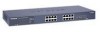
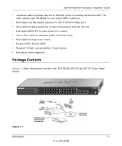
... high, rack-mountable 17-inch chassis. • Fan speed control supported. Package Contents Figure 1-1 shows the package contents of the NETGEAR GS716T and GS724T Series Smart Switch. Reset PWR ® ProSafe 24 Port Gigabit Smart Switch 1 3 5 7 9 11 13 15 17 19 21 23 LINK/ACT SPD Green (1000M) Yellow (100M) FDX 2 4 6 8 10 12 14 16 18...
... high, rack-mountable 17-inch chassis. • Fan speed control supported. Package Contents Figure 1-1 shows the package contents of the NETGEAR GS716T and GS724T Series Smart Switch. Reset PWR ® ProSafe 24 Port Gigabit Smart Switch 1 3 5 7 9 11 13 15 17 19 21 23 LINK/ACT SPD Green (1000M) Yellow (100M) FDX 2 4 6 8 10 12 14 16 18...

GS716Tv2/GS724Tv3 Hardware manual
Page 11
... capable of sensing the line speed and negotiating the operation duplex mode with the link partner automatically Figure 2-1 illustrates the NETGEAR GS716T Smart Switch front panel: System LEDs Reset PWR ® ProSafe 16 Port Gigabit Smart Switch 1 3 5 7 9 11 13 15 LINK/ACT SPD Green (1000M) Yellow (100M) FDX 2 4 6 8 10 12 14 16 LINK/ACT SPD FDX...
... capable of sensing the line speed and negotiating the operation duplex mode with the link partner automatically Figure 2-1 illustrates the NETGEAR GS716T Smart Switch front panel: System LEDs Reset PWR ® ProSafe 16 Port Gigabit Smart Switch 1 3 5 7 9 11 13 15 LINK/ACT SPD Green (1000M) Yellow (100M) FDX 2 4 6 8 10 12 14 16 LINK/ACT SPD FDX...
GS716Tv2/GS724Tv3 Hardware manual
Page 12
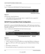
...System LEDs Figure 2-2 illustrates the NETGEAR GS716T Smart Switch back panel: 100-240V ~ 50-60Hz Figure 2-2 RS-232 Power Connector The back panel contains the following : • 24 RJ-45 connectors for 10/100/1000 Mbps auto-sensing Gigabit Ethernet switching ports. • Two slots ...of sensing the line speed and negotiating the operation duplex mode with the link partner automatically Figure 2-3 illustrates the NETGEAR GS724T Smart Switch front panel: System LEDs Reset PWR ® ProSafe 24 Port Gigabit Smart Switch 1 3 5 7 9 11 13 15 17 19 21 23 LINK/ACT SPD Green (1000M) Yellow (100M...
...System LEDs Figure 2-2 illustrates the NETGEAR GS716T Smart Switch back panel: 100-240V ~ 50-60Hz Figure 2-2 RS-232 Power Connector The back panel contains the following : • 24 RJ-45 connectors for 10/100/1000 Mbps auto-sensing Gigabit Ethernet switching ports. • Two slots ...of sensing the line speed and negotiating the operation duplex mode with the link partner automatically Figure 2-3 illustrates the NETGEAR GS724T Smart Switch front panel: System LEDs Reset PWR ® ProSafe 24 Port Gigabit Smart Switch 1 3 5 7 9 11 13 15 17 19 21 23 LINK/ACT SPD Green (1000M) Yellow (100M...
GS716Tv2/GS724Tv3 Hardware manual
Page 24
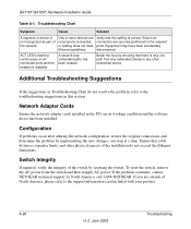
GS716T/GS724T Hardware Installation Guide Table A-1. Network Adapter Cards Ensure the network adapter cards installed in the required ports. Ensure that cable distances, repeater limits, and other networked device. To reset the switch, remove the AC power from any networked device to any other physical ...aspects of the network. In North America, call 1-888-NETGEAR. Verify that there is only one step at a time. ...
GS716T/GS724T Hardware Installation Guide Table A-1. Network Adapter Cards Ensure the network adapter cards installed in the required ports. Ensure that cable distances, repeater limits, and other networked device. To reset the switch, remove the AC power from any networked device to any other physical ...aspects of the network. In North America, call 1-888-NETGEAR. Verify that there is only one step at a time. ...
GS716Tv2/GS724Tv3 Hardware manual
Page 29
... 2-6 100BASE-TX 1-2 10BASE-T 1-2 1U 1-3 8-pin 2-8 A AC Power 2-6, 2-7 AGM731F 2-9 AGM732F 2-9 AGM733 2-9 Applying AC Power 4-17 Attaching Switch to a Rack 4-15 Auto Sensing 1-2 Auto Uplink 2-8, 2-9 Auto-negotiating 1-2 Auto-sensing 2-8 B Back-pressure 1-3 Brackets 4-14 C Category 5 Unshielded... 1-1 Combo Port 2-9 Combo Ports 1-2 Connecting Devices to the Switch 4-16 Copper 1-1 Crossover 2-8 D Default IP Address 4-18 Default Reset Button 2-5, 2-6 Device Hardware Interfaces 2-8 Duplex Mode 2-8 E Example of Desktop Switching 3-11 F Factory Default Button 2-9 Factory Defaults 2-5 Fiber Connectivity...
... 2-6 100BASE-TX 1-2 10BASE-T 1-2 1U 1-3 8-pin 2-8 A AC Power 2-6, 2-7 AGM731F 2-9 AGM732F 2-9 AGM733 2-9 Applying AC Power 4-17 Attaching Switch to a Rack 4-15 Auto Sensing 1-2 Auto Uplink 2-8, 2-9 Auto-negotiating 1-2 Auto-sensing 2-8 B Back-pressure 1-3 Brackets 4-14 C Category 5 Unshielded... 1-1 Combo Port 2-9 Combo Ports 1-2 Connecting Devices to the Switch 4-16 Copper 1-1 Crossover 2-8 D Default IP Address 4-18 Default Reset Button 2-5, 2-6 Device Hardware Interfaces 2-8 Duplex Mode 2-8 E Example of Desktop Switching 3-11 F Factory Default Button 2-9 Factory Defaults 2-5 Fiber Connectivity...

GS716Tv2/GS724Tv3 Hardware manual
Page 30
...Flow Control 1-3 Phillips Screwdriver 4-14 Index-28 Port LEDs 2-7 Power cord 1-4 Preparing the Site 4-13 R Rack 4-14 Rack-mount Kit 1-4, 4-14 Reset Button 2-5, 2-6 RJ-45 1-2 RJ-45 Ports 2-8 Rubber footpads 1-4, 4-14 S SFP GBIC Module 2-9 SFP LINK/ACT LED 2-8 SFP Module Bay ...4-17 Site Requirements 4-13 Small Form-factor Pluggable (SFP) 1-2 Smart Switch Resource CD 1-4 Smart Wizard Discovery 1-2 Straight-through 2-8 Support Information Card 1-4 System LEDs 2-8 T Temperature 4-14 Traffic Control 1-1 Troubleshooting Chart A-19 U ...
...Flow Control 1-3 Phillips Screwdriver 4-14 Index-28 Port LEDs 2-7 Power cord 1-4 Preparing the Site 4-13 R Rack 4-14 Rack-mount Kit 1-4, 4-14 Reset Button 2-5, 2-6 RJ-45 1-2 RJ-45 Ports 2-8 Rubber footpads 1-4, 4-14 S SFP GBIC Module 2-9 SFP LINK/ACT LED 2-8 SFP Module Bay ...4-17 Site Requirements 4-13 Small Form-factor Pluggable (SFP) 1-2 Smart Switch Resource CD 1-4 Smart Wizard Discovery 1-2 Straight-through 2-8 Support Information Card 1-4 System LEDs 2-8 T Temperature 4-14 Traffic Control 1-1 Troubleshooting Chart A-19 U ...
GS716T Hardware manual
Page 3
...SFP GBIC Module ...10 LED Descriptions ...10 Reset Button ...10 Factory Defaults Button ...11 CHAPTER 3: APPLICATIONS...12 Desktop Switching ...12 Backbone Switching ...13 CHAPTER 4: INSTALLATION...14 Step 1: Preparing the Site ...14 Step 2: Installing the Switch ...14 Step 3: Checking the Installation...15 ...Step 4: Connecting Devices to the Switch...15 Step 5: Installing a SFP GBIC Module ...15 Step 6: Applying AC Power ...16 Step 7: Switch Management through a Web Browser or Utility Program (...
...SFP GBIC Module ...10 LED Descriptions ...10 Reset Button ...10 Factory Defaults Button ...11 CHAPTER 3: APPLICATIONS...12 Desktop Switching ...12 Backbone Switching ...13 CHAPTER 4: INSTALLATION...14 Step 1: Preparing the Site ...14 Step 2: Installing the Switch ...14 Step 3: Checking the Installation...15 ...Step 4: Connecting Devices to the Switch...15 Step 5: Installing a SFP GBIC Module ...15 Step 6: Applying AC Power ...16 Step 7: Switch Management through a Web Browser or Utility Program (...

GS716T Hardware manual
Page 4
RESET BUTTON OF THE GS716T GIGABIT SMART SWITCH ...10 FIGURE 2-4. EXAMPLE OF BACKBONE SWITCHING ...13 FIGURE 4-1. PACKAGE CONTENTS ...8 FIGURE 2-1. FRONT PANEL OF THE GS716T GIGABIT SMART SWITCH ...9 FIGURE 2-2. INSTALLING A SFP GBIC MODULE INTO GS716T ...16 Page 4 of 20 Figures FIGURE 1-1. BACK PANEL OF THE GS716T GIGABIT SMART SWITCH ...9 FIGURE 2-3. FACTORY DEFAULTS BUTTON OF THE GS716T GIGABIT SMART SWITCH 11 FIGURE 3-1. CONNECTING DEVICES TO THE SWITCH ...15 FIGURE 4-3. ATTACHING MOUNTING BRACKETS...15 FIGURE 4-2. EXAMPLE OF DESKTOP SWITCHING...12 FIGURE 3-2.
RESET BUTTON OF THE GS716T GIGABIT SMART SWITCH ...10 FIGURE 2-4. EXAMPLE OF BACKBONE SWITCHING ...13 FIGURE 4-1. PACKAGE CONTENTS ...8 FIGURE 2-1. FRONT PANEL OF THE GS716T GIGABIT SMART SWITCH ...9 FIGURE 2-2. INSTALLING A SFP GBIC MODULE INTO GS716T ...16 Page 4 of 20 Figures FIGURE 1-1. BACK PANEL OF THE GS716T GIGABIT SMART SWITCH ...9 FIGURE 2-3. FACTORY DEFAULTS BUTTON OF THE GS716T GIGABIT SMART SWITCH 11 FIGURE 3-1. CONNECTING DEVICES TO THE SWITCH ...15 FIGURE 4-3. ATTACHING MOUNTING BRACKETS...15 FIGURE 4-2. EXAMPLE OF DESKTOP SWITCHING...12 FIGURE 3-2.
GS716T Hardware manual
Page 7
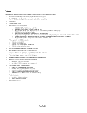
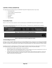
...of the NETGEAR ProSafe GS716T Gigabit Smart Switch. • Sixteen 10/100/1000 Mbps auto-sensing Gigabit Ethernet switching ports • Two SFP GBIC combo Gigabit Ethernet slots for optional fiber connectivity • Reset Button • Factory Defaults Button • Administrative switch management ... follow control ♦ Support Auto-Discovery application program for discovering and managing the smart switches on the network ♦ Support flash upgrading, configuration backup/restore and factory reset • Full compatibility with IEEE standards: o IEEE 802.3i (10BASE-T) o IEEE...
...of the NETGEAR ProSafe GS716T Gigabit Smart Switch. • Sixteen 10/100/1000 Mbps auto-sensing Gigabit Ethernet switching ports • Two SFP GBIC combo Gigabit Ethernet slots for optional fiber connectivity • Reset Button • Factory Defaults Button • Administrative switch management ... follow control ♦ Support Auto-Discovery application program for discovering and managing the smart switches on the network ♦ Support flash upgrading, configuration backup/restore and factory reset • Full compatibility with IEEE standards: o IEEE 802.3i (10BASE-T) o IEEE...
GS716T Hardware manual
Page 9
...; LED descriptions • Reset button • Factory defaults button Front and Back Panels Figures 2-1 and 2-2 show the key components on the front and back panels of the attached device. Figure 2-1. or full-duplex) of the NETGEAR ProSafe GS716T Gigabit Smart Switch. Front Panel of 20 ... the attached device, without requiring user intervention. Page 9 of the GS716T Gigabit Smart Switch Figure 2-2. Back Panel of the NETGEAR ProSafe GS716T Gigabit Smart Switch. When you insert a cable into an RJ-45 port, the switch automatically ascertains the maximum speed (10 or 100 or 1000 Mbps) ...
...; LED descriptions • Reset button • Factory defaults button Front and Back Panels Figures 2-1 and 2-2 show the key components on the front and back panels of the attached device. Figure 2-1. or full-duplex) of the NETGEAR ProSafe GS716T Gigabit Smart Switch. Front Panel of 20 ... the attached device, without requiring user intervention. Page 9 of the GS716T Gigabit Smart Switch Figure 2-2. Back Panel of the NETGEAR ProSafe GS716T Gigabit Smart Switch. When you insert a cable into an RJ-45 port, the switch automatically ascertains the maximum speed (10 or 100 or 1000 Mbps) ...
GS716T Hardware manual
Page 10
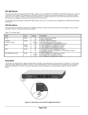
LED Descriptions The front panel of the NETGEAR ProSafe GS716T Gigabit Smart Switch has LEDs that is occurring on the switch. Table 2-1. Power is supplied to the switch. Port has a valid link connection. Figure 2-3. Front Panel LEDs Label Power Link/ACT (The port number) SPD FDX SFP (MiniGBIC) ..., both connectors are combo ports, sharing a connection with the IEEE 802.3Z 1000 BaseSX Standard. This is occurring on as it resets. Data transmission is equivalent to turning the power off and back on the port Data transmission is compatible with the last two RJ-45...
LED Descriptions The front panel of the NETGEAR ProSafe GS716T Gigabit Smart Switch has LEDs that is occurring on the switch. Table 2-1. Power is supplied to the switch. Port has a valid link connection. Figure 2-3. Front Panel LEDs Label Power Link/ACT (The port number) SPD FDX SFP (MiniGBIC) ..., both connectors are combo ports, sharing a connection with the IEEE 802.3Z 1000 BaseSX Standard. This is occurring on as it resets. Data transmission is equivalent to turning the power off and back on the port Data transmission is compatible with the last two RJ-45...

GS716T Hardware manual
Page 19
...device supports autonegotiation. In North America, call 1-888-NETGEAR. Auto Negotiation The 10/100/1000 Mbps ports negotiate the correct duplex mode and speed if the device at both the switch and the connecting device Make sure all products are ... your product. To reset the switch, use the Tools> Reset command or remove AC power from any networked device to half-duplex. If the problem continues, contact NETGEAR technical support. APPENDIX B: TROUBLESHOOTING This chapter provides information about troubleshooting the NETGEAR ProSafe GS716T Gigabit Smart Switch. Topics include: o...
...device supports autonegotiation. In North America, call 1-888-NETGEAR. Auto Negotiation The 10/100/1000 Mbps ports negotiate the correct duplex mode and speed if the device at both the switch and the connecting device Make sure all products are ... your product. To reset the switch, use the Tools> Reset command or remove AC power from any networked device to half-duplex. If the problem continues, contact NETGEAR technical support. APPENDIX B: TROUBLESHOOTING This chapter provides information about troubleshooting the NETGEAR ProSafe GS716T Gigabit Smart Switch. Topics include: o...


