NP115 : ceiling plate technical data sheet
Page 1
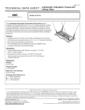
...383 recommended) and antenna leads. It can be used in conjunction with a 1 1/2-11.5 NPS center threaded fitting and holes for a clean finish • Pre-assembled, easy to install...tune the level of Peerless Industries, Inc. Peerless Industries, Inc. 3215 W. Peerless is specifically designed for mounting • Unlimited projector placement above a 2' x 2' or 2' x 4' false ceiling tile. Assembly ...(48 mm) ARCHITECTS SPECIFICATIONS The Lightweight Adjustable Suspended Ceiling Plate shall be a NEC model SCP 100 and shall be used with turnbuckles to complement sleek, lightweight ...
...383 recommended) and antenna leads. It can be used in conjunction with a 1 1/2-11.5 NPS center threaded fitting and holes for a clean finish • Pre-assembled, easy to install...tune the level of Peerless Industries, Inc. Peerless Industries, Inc. 3215 W. Peerless is specifically designed for mounting • Unlimited projector placement above a 2' x 2' or 2' x 4' false ceiling tile. Assembly ...(48 mm) ARCHITECTS SPECIFICATIONS The Lightweight Adjustable Suspended Ceiling Plate shall be a NEC model SCP 100 and shall be used with turnbuckles to complement sleek, lightweight ...
NP115 : ceiling plate instruction
Page 1
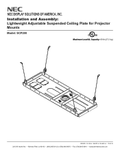
Installation and Assembly: Lightweight Adjustable Suspended Ceiling Plate for Projector Mounts Model: SCP200 C U© L US Maximum Load UL Capacity: 60 lb (27.2 kg) ISSUED: 12-16-04 SHEET #: 120-9015-3 11-05-10 3215 W. NEC DISPLAY SOLUTIONS OF AMERICA, INC. North Ave. • Melrose Park, IL 60160 • (800) 865-2112 or (708) 865-8870 • Fax: (708) 865-2941 • www.peerlessmounts.com
Installation and Assembly: Lightweight Adjustable Suspended Ceiling Plate for Projector Mounts Model: SCP200 C U© L US Maximum Load UL Capacity: 60 lb (27.2 kg) ISSUED: 12-16-04 SHEET #: 120-9015-3 11-05-10 3215 W. NEC DISPLAY SOLUTIONS OF AMERICA, INC. North Ave. • Melrose Park, IL 60160 • (800) 865-2112 or (708) 865-8870 • Fax: (708) 865-2941 • www.peerlessmounts.com
NP115 : ceiling plate instruction
Page 2
... the supporting surface will safely support the combined load of 6 ISSUED: 12-16-04 SHEET #: 120-9015-3 11-05-10 For Technical Support Contact Peerless Mounts at www.peerlessmounts.com 2 of the equipment and all attached hardware and components. • Never exceed the Maximum UL Load Capacity. • Always use an... understood the instructions and warnings contained in this product outdoors could lead to product failure and personal injury. • When installing or adjusting the ceiling mount, do not overtighten.
... the supporting surface will safely support the combined load of 6 ISSUED: 12-16-04 SHEET #: 120-9015-3 11-05-10 For Technical Support Contact Peerless Mounts at www.peerlessmounts.com 2 of the equipment and all attached hardware and components. • Never exceed the Maximum UL Load Capacity. • Always use an... understood the instructions and warnings contained in this product outdoors could lead to product failure and personal injury. • When installing or adjusting the ceiling mount, do not overtighten.
NP115 : ceiling plate instruction
Page 3
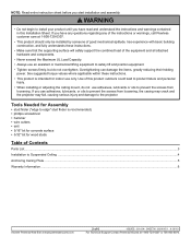
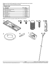
...Parts List Description A ceiling plate B M5 x 10 mm penta pin screw C M5 penta pin driver D M5 x 10 mm self tapping screw E steel cable F flush mount tube G wood screw H concrete anchor I E Visit the Peerless Web Site at www.peerlessmounts.com 3 of the parts shown are included. Part # 1 055-2983 1 ... 1 1418-001A NOTE: Some parts may not need all of 6 ISSUED: 12-16-04 SHEET #: 120-9015-3 11-05-10 For Technical Support Contact Peerless Mounts at 1-800-729-0307 or 708-865-8870. A B D F G H J C I cable lock J escutcheon plate Qty. Before you start check the parts list to ...
...Parts List Description A ceiling plate B M5 x 10 mm penta pin screw C M5 penta pin driver D M5 x 10 mm self tapping screw E steel cable F flush mount tube G wood screw H concrete anchor I E Visit the Peerless Web Site at www.peerlessmounts.com 3 of the parts shown are included. Part # 1 055-2983 1 ... 1 1418-001A NOTE: Some parts may not need all of 6 ISSUED: 12-16-04 SHEET #: 120-9015-3 11-05-10 For Technical Support Contact Peerless Mounts at 1-800-729-0307 or 708-865-8870. A B D F G H J C I cable lock J escutcheon plate Qty. Before you start check the parts list to ...
NP115 : ceiling plate instruction
Page 4
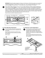
...electrical box. A F For Extension Column Applications 3 From the bottom up, thread extension column (not included) up through retaining collar in adjustable collar mount plate. A B 1 1/2" EXTENSION COLUMN (SOLD SEPARATELY) (UL LISTED EXT OR AEC SERIES) Visit the Peerless Web Site at www.peerlessmounts.com...in desired position and install 1/4-20 self tapping screws (D) into sides of ceiling tray (A) rests on ceiling tray (A). Slide collar mount plate back into position and tighten all carriage bolts and wing nuts. IMPORTANT: Ceiling Tray (A) is low install screw (D) into lower...
...electrical box. A F For Extension Column Applications 3 From the bottom up, thread extension column (not included) up through retaining collar in adjustable collar mount plate. A B 1 1/2" EXTENSION COLUMN (SOLD SEPARATELY) (UL LISTED EXT OR AEC SERIES) Visit the Peerless Web Site at www.peerlessmounts.com...in desired position and install 1/4-20 self tapping screws (D) into sides of ceiling tray (A) rests on ceiling tray (A). Slide collar mount plate back into position and tighten all carriage bolts and wing nuts. IMPORTANT: Ceiling Tray (A) is low install screw (D) into lower...

NP115 : ceiling plate instruction
Page 5
...ISSUED: 12-16-04 SHEET #: 120-9015-3 11-05-10 Visit the Peerless Web Site at www.peerlessmounts.com For Technical Support Contact Peerless Mounts at 15°. Loop steel cables through cable lock as shown in figure 5.2. holes to a minimum depth of steel wire (E) ...cable lock. Finish by the steel cables. E FIGURE 5.1 DETAIL 3 - All other end of steel cable through cable lock until all attached components (Projector Mount, Extension Column, etc.) and equipment. 5 Insert loose end of 2.25" (57 mm). WARNING • It is the responsibility of cable loop. ...
...ISSUED: 12-16-04 SHEET #: 120-9015-3 11-05-10 Visit the Peerless Web Site at www.peerlessmounts.com For Technical Support Contact Peerless Mounts at 15°. Loop steel cables through cable lock as shown in figure 5.2. holes to a minimum depth of steel wire (E) ...cable lock. Finish by the steel cables. E FIGURE 5.1 DETAIL 3 - All other end of steel cable through cable lock until all attached components (Projector Mount, Extension Column, etc.) and equipment. 5 Insert loose end of 2.25" (57 mm). WARNING • It is the responsibility of cable loop. ...

NP115 : ceiling plate instruction
Page 6
... will repair or replace, or refund the purchase price of 6 ISSUED: 12-16-04 SHEET #: 120-9015-3 11-05-10 For Technical Support Contact Peerless Mounts at 1-800-729-0307 or 708-865-8870. www.peerlessmounts.com © 2008 Peerless Industries, Inc.
... will repair or replace, or refund the purchase price of 6 ISSUED: 12-16-04 SHEET #: 120-9015-3 11-05-10 For Technical Support Contact Peerless Mounts at 1-800-729-0307 or 708-865-8870. www.peerlessmounts.com © 2008 Peerless Industries, Inc.

NP115 : ceiling plate instruction
Page 1
...20 x 3/8" screws (not shown) 1/4"-20 nuts (not shown) allen wrench turnbuckle 20' (6.1m) tie wire (not shown) eye bolt concrete anchor flush mount tube M5 x 10 mm penta pin screw M5 x 1" penta pin driver escutcheon ring PART # 055-0492 520-2015 530-9302 560-9706 560-9620 600...is intended for use only to exceed maximum load capacity. Visit the Peerless Web Site at www.peerlessindustries.com 1 of projector and mount not to support Projector Mounts or other products as specified by Peerless. Recommended tools: Phillips screwdriver, hammer and wire cutters, drill and drill bits. Please read...
...20 x 3/8" screws (not shown) 1/4"-20 nuts (not shown) allen wrench turnbuckle 20' (6.1m) tie wire (not shown) eye bolt concrete anchor flush mount tube M5 x 10 mm penta pin screw M5 x 1" penta pin driver escutcheon ring PART # 055-0492 520-2015 530-9302 560-9706 560-9620 600...is intended for use only to exceed maximum load capacity. Visit the Peerless Web Site at www.peerlessindustries.com 1 of projector and mount not to support Projector Mounts or other products as specified by Peerless. Recommended tools: Phillips screwdriver, hammer and wire cutters, drill and drill bits. Please read...

NP115 : ceiling plate instruction
Page 2
... collar in collar and fasten using a 7/16" wrench. Place in desired position and tighten knurled knobs until flush with hole in adjustable collar mount plate. Using hole in figure 2. Visit the Peerless Web Site at www.peerlessindustries.com F figure 2 2 of the way. Ceiling runners (...see DETAIL 2, page 3) should have a "T" cross section and a minimum height of ceiling tray (A) rests on ceiling runners as shown in collar mount plate, mark false ceiling tile where hole will be best to install ceiling anchors (step 5) before installing the ceiling tray (step 1). Cut out...
... collar in collar and fasten using a 7/16" wrench. Place in desired position and tighten knurled knobs until flush with hole in adjustable collar mount plate. Using hole in figure 2. Visit the Peerless Web Site at www.peerlessindustries.com F figure 2 2 of the way. Ceiling runners (...see DETAIL 2, page 3) should have a "T" cross section and a minimum height of ceiling tray (A) rests on ceiling runners as shown in collar mount plate, mark false ceiling tile where hole will be best to install ceiling anchors (step 5) before installing the ceiling tray (step 1). Cut out...

NP115 : ceiling plate instruction
Page 3
... support the combined load of the ceiling tray should be supported by adjusting turnbuckles (F). Peerless is complete, the weight of all components (Projector Mount, Extension Column, etc.) and equipment have been attached, tension the tie wires by the tie wires. holes 1.5" (38 mm) deep. After... all attached components (Projector Mount, Extension Column, etc.) and equipment. • Never attach hooks to ends of Peerless Industries, Inc. Wood Joists or Beams Drill 5/32" (...
... support the combined load of the ceiling tray should be supported by adjusting turnbuckles (F). Peerless is complete, the weight of all components (Projector Mount, Extension Column, etc.) and equipment have been attached, tension the tie wires by the tie wires. holes 1.5" (38 mm) deep. After... all attached components (Projector Mount, Extension Column, etc.) and equipment. • Never attach hooks to ends of Peerless Industries, Inc. Wood Joists or Beams Drill 5/32" (...
NP115 : Whitepaper Projector Placement Comparison
Page 1
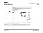
...necdisplay.com PJ Placement Page 1 of their respective zoom range. Whitepaper Projector Placement Comparison NEC Display Solutions of America, Inc. Ver. 4.0 Ceiling Mounted Installation Ceiling Color Chart Red = M260X/260W/300X/300W, P350X/350W/420X, NP901W/...NP905 Blue = NP1150/NP2150/NP3150/NP3151W, NP3250/NP3250W/NP2250/NP1250, NP2200/NP1200 Brown = NP4000/NP4001, NP4100/NP4100W Black = NP41/NP61/NP62, NP43/NP64 Magenta = NP510WS/NP610S Green = NP110/NP115/NP215/NP216 Gray = U300X/U310W...
...necdisplay.com PJ Placement Page 1 of their respective zoom range. Whitepaper Projector Placement Comparison NEC Display Solutions of America, Inc. Ver. 4.0 Ceiling Mounted Installation Ceiling Color Chart Red = M260X/260W/300X/300W, P350X/350W/420X, NP901W/...NP905 Blue = NP1150/NP2150/NP3150/NP3151W, NP3250/NP3250W/NP2250/NP1250, NP2200/NP1200 Brown = NP4000/NP4001, NP4100/NP4100W Black = NP41/NP61/NP62, NP43/NP64 Magenta = NP510WS/NP610S Green = NP110/NP115/NP215/NP216 Gray = U300X/U310W...

NP215 : NP01UCM spec brochure
Page 1
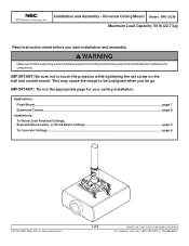
Ceiling Mount Model: NP01UCM Maximum Load Capacity: 50 lb (22.7 kg) Read instruction sheet before you let go. Universal NEC DISPLAY SOLUTIONS OF AMERICA, INC. WARNING • Make sure that the supporting surface will safely support the combined load of 9 ...8870. Table of Contents Parts List ...2 To Wood Joist Finished Ceilings, Exposed Wood Joists or Wood Beam Ceilings 4 To Concrete Ceilings ...5 Flush Mount ...6 Extension Column ...7 Attaching Universal Adapter Plate to be unaligned when you start installation and assembly. IMPORTANT! IMPORTANT! This may cause the image ...
Ceiling Mount Model: NP01UCM Maximum Load Capacity: 50 lb (22.7 kg) Read instruction sheet before you let go. Universal NEC DISPLAY SOLUTIONS OF AMERICA, INC. WARNING • Make sure that the supporting surface will safely support the combined load of 9 ...8870. Table of Contents Parts List ...2 To Wood Joist Finished Ceilings, Exposed Wood Joists or Wood Beam Ceilings 4 To Concrete Ceilings ...5 Flush Mount ...6 Extension Column ...7 Attaching Universal Adapter Plate to be unaligned when you start installation and assembly. IMPORTANT! IMPORTANT! This may cause the image ...

NP215 : NP01UCM spec brochure
Page 2
... 9 Q B Fasteners ISSUED: 04-11-06 SHEET #: 055-9458-6 09-25-09 For customer care call 1-800-729-0307 or 708-865-8870. A ball and socket mount 1 B 4 mm security allen wrench 1 C M5 x .8 x 10 mm socket pin type F screw 1 D #10-32 x 3/8" spade thumb screw 1 E #10-32 x 3/8" serrated washer head socket pin screw 1 F #14...
... 9 Q B Fasteners ISSUED: 04-11-06 SHEET #: 055-9458-6 09-25-09 For customer care call 1-800-729-0307 or 708-865-8870. A ball and socket mount 1 B 4 mm security allen wrench 1 C M5 x .8 x 10 mm socket pin type F screw 1 D #10-32 x 3/8" spade thumb screw 1 E #10-32 x 3/8" serrated washer head socket pin screw 1 F #14...

NP215 : NP01UCM spec brochure
Page 4
Overtightening can damage the screws, greatly reducing their holding power. • Never tighten in excess of 80 in • lb (9 N.M.). • Make sure that mounting screws are anchored into the joist CENTER! Skip to drill holes into the center of an "edge to edge" stud finder is highly recommended. 1 Drill ...
Overtightening can damage the screws, greatly reducing their holding power. • Never tighten in excess of 80 in • lb (9 N.M.). • Make sure that mounting screws are anchored into the joist CENTER! Skip to drill holes into the center of an "edge to edge" stud finder is highly recommended. 1 Drill ...

NP215 : NP01UCM spec brochure
Page 5
... be used for attachment to concrete ceiling covered with plaster / drywall is highly recommended. Installation to Concrete Ceilings WARNING • When installing ceiling mounts on concrete, verify that you have a minimum of 1 5/8" of actual concrete surface in the 1/4" diameter hole to a minimum depth of.... The use of an "edge to verify that the ceiling will safely support the combined load of the studs. If mounting to concrete ceilings covered with screw 3 F concrete anchor After repeating step one tighten all fasteners. INCORRECT CORRECT metal bracket concrete...
... be used for attachment to concrete ceiling covered with plaster / drywall is highly recommended. Installation to Concrete Ceilings WARNING • When installing ceiling mounts on concrete, verify that you have a minimum of 1 5/8" of actual concrete surface in the 1/4" diameter hole to a minimum depth of.... The use of an "edge to verify that the ceiling will safely support the combined load of the studs. If mounting to concrete ceilings covered with screw 3 F concrete anchor After repeating step one tighten all fasteners. INCORRECT CORRECT metal bracket concrete...

NP215 : NP01UCM spec brochure
Page 6
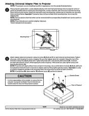
... CEILING G A C A K NOTCH G DETAIL 1 Visit the Peerless Web Site at www.peerlessmounts.com 6 of the ceiling plate (G) and secure ball and socket mount (A) with a M5 x 10 mm socket pin screw (C) using security allen wrench (B) as shown in detail 1. Align the notch with one of the four holes of...ISSUED: 04-11-06 SHEET #: 055-9458-6 09-25-09 For customer care call 1-800-729-0307 or 708-865-8870. Flush Mount Application 1 Screw ball and socket mount (A) into ceiling plate (G). overtightening screw will damage threads making it difficult to step 3. NOTE: Slotted set screw (K) is used to...
... CEILING G A C A K NOTCH G DETAIL 1 Visit the Peerless Web Site at www.peerlessmounts.com 6 of the ceiling plate (G) and secure ball and socket mount (A) with a M5 x 10 mm socket pin screw (C) using security allen wrench (B) as shown in detail 1. Align the notch with one of the four holes of...ISSUED: 04-11-06 SHEET #: 055-9458-6 09-25-09 For customer care call 1-800-729-0307 or 708-865-8870. Flush Mount Application 1 Screw ball and socket mount (A) into ceiling plate (G). overtightening screw will damage threads making it difficult to step 3. NOTE: Slotted set screw (K) is used to...

NP215 : NP01UCM spec brochure
Page 7
... Do not overtighten screws; See detail 6. NOTE: Slotted set screws (K) are used to extension column. See detail 5. Screw ball and socket mount (A) to extension column connector (I ) to jam against the threads of 9 ISSUED: 04-11-06 SHEET #: 055-9458-6 09-25-09...A screws will damage threads making it difficult to ceiling plate (G). See detail 4. Insert and tighten one of the four holes in ball and socket mount (A) using security allen wrench (B). Align slot in extension column with one #10-32 x 3/8" socket pin screw (J) through extension column connector (I ...
... Do not overtighten screws; See detail 6. NOTE: Slotted set screws (K) are used to extension column. See detail 5. Screw ball and socket mount (A) to extension column connector (I ) to jam against the threads of 9 ISSUED: 04-11-06 SHEET #: 055-9458-6 09-25-09...A screws will damage threads making it difficult to ceiling plate (G). See detail 4. Insert and tighten one of the four holes in ball and socket mount (A) using security allen wrench (B). Align slot in extension column with one #10-32 x 3/8" socket pin screw (J) through extension column connector (I ...
NP215 : NP01UCM spec brochure
Page 8
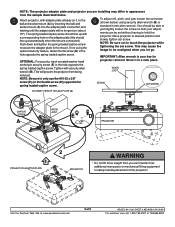
... Attach adapter plate (L) to keep the adapter plate level. Adjust the feet of the channels to projector using one channel for each mounting hole, position feet of projector. Important: In order to ensure that the projector is properly ventilated. NOTE: If using screw (M), place...combination of screws (M, N, O, or P) and foot adjustment that adapter plate (L) is the responsibility of gravity as close to raise the mount off the projector surface. Feet of channels are used to projector center of the installer to properly engage the threads in position retighten fasteners...
... Attach adapter plate (L) to keep the adapter plate level. Adjust the feet of the channels to projector using one channel for each mounting hole, position feet of projector. Important: In order to ensure that the projector is properly ventilated. NOTE: If using screw (M), place...combination of screws (M, N, O, or P) and foot adjustment that adapter plate (L) is the responsibility of gravity as close to raise the mount off the projector surface. Feet of channels are used to projector center of the installer to properly engage the threads in position retighten fasteners...
NP215 : NP01UCM spec brochure
Page 9
...the adapter plate (this should line up with security allen wrench (B). Store it , to the ball and socket mount (A) by inserting the ball and socket mount (A) into the adapter plate connection and twisting until the adapter plate will prevent the projector from the sample illustrated ... thumb screw (D) in a safe place. This will no longer turn (about 75°). Use additional man power or mechanical lifting equipment to the mount. If not using security allen wrench (B) or standard 4 mm allen wrench. CEILING SET SCREW CUTAWAY VIEW OF CEILING PLATE (G) CEILING CAPTIVE SCREW A...
...the adapter plate (this should line up with security allen wrench (B). Store it , to the ball and socket mount (A) by inserting the ball and socket mount (A) into the adapter plate connection and twisting until the adapter plate will prevent the projector from the sample illustrated ... thumb screw (D) in a safe place. This will no longer turn (about 75°). Use additional man power or mechanical lifting equipment to the mount. If not using security allen wrench (B) or standard 4 mm allen wrench. CEILING SET SCREW CUTAWAY VIEW OF CEILING PLATE (G) CEILING CAPTIVE SCREW A...
NP216 : NP01UCM (ceiling mount) instructions
Page 1
... the image to touch the projector while tightening the set screw on the ball and socket mount. Be sure not to be unaligned when you start installation and assembly. Applications: Flush Mount ...page 7 Extension Column ...page 8 Installations: To Wood Joist Finished Ceilings, Exposed Wood ...Joists, or Wood Beam Ceilings page 5 To Concrete Ceilings ...page 6 Visit the NEC Web Site at www.necsam.com 1 of the equipment...
... the image to touch the projector while tightening the set screw on the ball and socket mount. Be sure not to be unaligned when you start installation and assembly. Applications: Flush Mount ...page 7 Extension Column ...page 8 Installations: To Wood Joist Finished Ceilings, Exposed Wood ...Joists, or Wood Beam Ceilings page 5 To Concrete Ceilings ...page 6 Visit the NEC Web Site at www.necsam.com 1 of the equipment...

