User Manual
Page 3
... 3.4.2 Owners of Electrical Equipment 17 3.4.3 Gateway Location 17 4 Installing Powerline MU 18 4.1 Two-Phase (Single-Phase) Installation 21 4.2 Three-Phase Installation 22 4.2.1 Mass Metered...23 4.2.2 Using a Panel Extender (multiple electrical panels 24 4.2.3 Individually Metered 25 4.2.4 Multiple Transformer 30 5 Hardware Installation 33 5.1 Upgrading Firmware 33 5.2 Equipment Staging 33 Page 3 of 112
... 3.4.2 Owners of Electrical Equipment 17 3.4.3 Gateway Location 17 4 Installing Powerline MU 18 4.1 Two-Phase (Single-Phase) Installation 21 4.2 Three-Phase Installation 22 4.2.1 Mass Metered...23 4.2.2 Using a Panel Extender (multiple electrical panels 24 4.2.3 Individually Metered 25 4.2.4 Multiple Transformer 30 5 Hardware Installation 33 5.1 Upgrading Firmware 33 5.2 Equipment Staging 33 Page 3 of 112
User Manual
Page 7
... IP Operating Mode (Normal 70 Figure 48 Typical Set Up for the Modem Repeater 71 Figure 49 Operating Mode (Repeater 71 Figure 50 Operating Mode (Use with Re;eater 72 Figure 51 VLAN Configuration (Modem 72 Figure 52 IP Address with NAT Enabled Screen 74 Figure 53 IP Address WAN 75...
... IP Operating Mode (Normal 70 Figure 48 Typical Set Up for the Modem Repeater 71 Figure 49 Operating Mode (Repeater 71 Figure 50 Operating Mode (Use with Re;eater 72 Figure 51 VLAN Configuration (Modem 72 Figure 52 IP Address with NAT Enabled Screen 74 Figure 53 IP Address WAN 75...
User Manual
Page 8
... THIS USER GUIDE In future issues, this section will identify features, descriptions, and revisions that underlies the specific information in the box. Page 8 of consistently used admonitions. Chapter 3 Chapter 5 This document also employs a set of 112
... THIS USER GUIDE In future issues, this section will identify features, descriptions, and revisions that underlies the specific information in the box. Page 8 of consistently used admonitions. Chapter 3 Chapter 5 This document also employs a set of 112
User Manual
Page 9
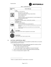
...Reader is a registered trademark of supported releases a. in the Table of action: 1. in mind. Visit the Canopy systems website at http://www.motorola.com/canopy. 3. WARNING! a notice that the risk of harm to person exists. 1.2 GETTING ADDITIONAL HELP To get information or assistance as soon... your action can disturb something that you should always keep in the Adobe Reader® search capability for keywords that you encounter, use the following sequence of Contents for the topic. CAUTION! IMPORTANT: informative content that may ◦ identify an indication that you may...
...Reader is a registered trademark of supported releases a. in the Table of action: 1. in mind. Visit the Canopy systems website at http://www.motorola.com/canopy. 3. WARNING! a notice that the risk of harm to person exists. 1.2 GETTING ADDITIONAL HELP To get information or assistance as soon... your action can disturb something that you should always keep in the Adobe Reader® search capability for keywords that you encounter, use the following sequence of Contents for the topic. CAUTION! IMPORTANT: informative content that may ◦ identify an indication that you may...
User Manual
Page 11
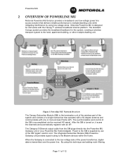
... Gateway unit provides signal routing to the hotel, apartment building, or other multiple dwelling unit. Powerline MU 2 OVERVIEW OF POWERLINE MU Motorola Powerline MU Solution provides a broadband over the power line. The Category 5 Ethernet output cable from the SM plugs directly into the ... via a Powerline MU Hybrid Adapter. By using low voltage wires. Figure 1 Powerline MU Network Overview The Canopy Subscriber Module (SM) is designed for the system, creating a wireless transport system to the Modem devices within the home. Motorola Powerline MU is the termination unit of the...
... Gateway unit provides signal routing to the hotel, apartment building, or other multiple dwelling unit. Powerline MU 2 OVERVIEW OF POWERLINE MU Motorola Powerline MU Solution provides a broadband over the power line. The Category 5 Ethernet output cable from the SM plugs directly into the ... via a Powerline MU Hybrid Adapter. By using low voltage wires. Figure 1 Powerline MU Network Overview The Canopy Subscriber Module (SM) is designed for the system, creating a wireless transport system to the Modem devices within the home. Motorola Powerline MU is the termination unit of the...
User Manual
Page 12
... private IP address. Page 12 of Modem isolation: A. Powerline MU to Powerline MU carriers, the potential for radio frequency interference is via Motorola's Prizm EMS. In addition to monitoring and maintaining the Powerline equipment, it tries to communicate with a Gateway. The recommended Authentication method is...Gateway, so the VLAN ID can be changed when the system is correct, the Gateway and the Modem establish one to Ethernet conversion, using 56-bit Data Encryption Standard (DES), the HomePlug standard. This is Virtual Local Area Network (VLAN) tagging. An Ethernet cable from...
... private IP address. Page 12 of Modem isolation: A. Powerline MU to Powerline MU carriers, the potential for radio frequency interference is via Motorola's Prizm EMS. In addition to monitoring and maintaining the Powerline equipment, it tries to communicate with a Gateway. The recommended Authentication method is...Gateway, so the VLAN ID can be changed when the system is correct, the Gateway and the Modem establish one to Ethernet conversion, using 56-bit Data Encryption Standard (DES), the HomePlug standard. This is Virtual Local Area Network (VLAN) tagging. An Ethernet cable from...
User Manual
Page 13
... to ensure the security of the Powerline MU system. 2.1.2 Bandwidth Management Individual modems may be set manually using the scheme recommended in the Modem. The network operator can also select one of eight levels of Quality ...of Service (QoS) for all traffic to and from that modem or can use three Type of Service (ToS) bits (three higher order DSCP bits), which are part of the IP header..., to 4 classes of service, using the Web page then it will be added as a part of the VLAN tag, not part of the...
... to ensure the security of the Powerline MU system. 2.1.2 Bandwidth Management Individual modems may be set manually using the scheme recommended in the Modem. The network operator can also select one of eight levels of Quality ...of Service (QoS) for all traffic to and from that modem or can use three Type of Service (ToS) bits (three higher order DSCP bits), which are part of the IP header..., to 4 classes of service, using the Web page then it will be added as a part of the VLAN tag, not part of the...
User Manual
Page 14
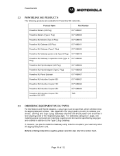
... couplers, you need only order the appropriate power cord. If, however, you plan to install the Gateway using G or I plugs, one matching power cord and one 6-foot power cord and three 3foot coupling cords of 112 See Appendix A for Powerline MU networks. Before ...
... couplers, you need only order the appropriate power cord. If, however, you plan to install the Gateway using G or I plugs, one matching power cord and one 6-foot power cord and three 3foot coupling cords of 112 See Appendix A for Powerline MU networks. Before ...
User Manual
Page 16
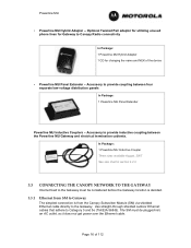
...termination cabinets. Accessory to the Gateway. The SM must be plugged into an AC outlet, as it does not get power over the Ethernet cable. Use straight-through shielded outdoor Ethernet cables that adhere to Canopy Radio connectivity In Package: 1 Powerline MU Hybrid Adapter 1 CD for changing the name and NEK... of 112 Optional Twisted Pair adapter for utilizing unused phone lines for Gateway to Category 5 and 5e (TIA/EIA 568-B). Powerline MU • Powerline MU Hybrid Adapter --
...termination cabinets. Accessory to the Gateway. The SM must be plugged into an AC outlet, as it does not get power over the Ethernet cable. Use straight-through shielded outdoor Ethernet cables that adhere to Canopy Radio connectivity In Package: 1 Powerline MU Hybrid Adapter 1 CD for changing the name and NEK... of 112 Optional Twisted Pair adapter for utilizing unused phone lines for Gateway to Category 5 and 5e (TIA/EIA 568-B). Powerline MU • Powerline MU Hybrid Adapter --
User Manual
Page 17
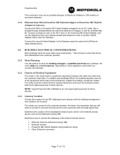
...may not be possible because of distances limitations (100 meters) or structural obstacles. 3.3.2 Ethernet from the Motorola Canopy SM) • Ethernet via fiber • Powerline MU Hybrid Adapter using the same kind of Ethernet cable defined above. 3.4 BUILDING ELECTRICAL CONSIDERATIONS Most buildings have the same basic... do not require gaining access to a Powerline MU Hybrid Adapter plugged in plans that is the Internet access device, such as the Motorola Canopy SM. Determine how to connect the Gateway to the Internet access device: • Ethernet (from SM to Powerline MU Hybrid...
...may not be possible because of distances limitations (100 meters) or structural obstacles. 3.3.2 Ethernet from the Motorola Canopy SM) • Ethernet via fiber • Powerline MU Hybrid Adapter using the same kind of Ethernet cable defined above. 3.4 BUILDING ELECTRICAL CONSIDERATIONS Most buildings have the same basic... do not require gaining access to a Powerline MU Hybrid Adapter plugged in plans that is the Internet access device, such as the Motorola Canopy SM. Determine how to connect the Gateway to the Internet access device: • Ethernet (from SM to Powerline MU Hybrid...

User Manual
Page 18
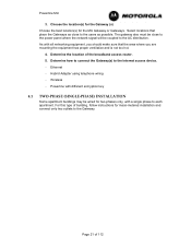
... accepted universally across all distribution points and electrical panels on the International Electrotechnical Commission (IEC) website (www.iec.ch). The symbols used in the building. NOTE: Every effort has been made when installing the Powerline MU, they must be found on the electrical diagram...Gateway placement. • Locate any modifications are made to gather information about the electrical system in the building in buildings that are used in some countries. Be sure you with your network. • Locate all countries. Thus such a diagram should be involved from...
... accepted universally across all distribution points and electrical panels on the International Electrotechnical Commission (IEC) website (www.iec.ch). The symbols used in the building. NOTE: Every effort has been made when installing the Powerline MU, they must be found on the electrical diagram...Gateway placement. • Locate any modifications are made to gather information about the electrical system in the building in buildings that are used in some countries. Be sure you with your network. • Locate all countries. Thus such a diagram should be involved from...
User Manual
Page 21
The gateway also must be coupled to the AC distribution. Page 21 of the broadband access router. 5. Wireless - Ethernet - Hybrid Adapter using telephone wiring - Powerline MU 3. Select locations that the area where you should make sure that place the Gateways as close to the power panel where ...
The gateway also must be coupled to the AC distribution. Page 21 of the broadband access router. 5. Wireless - Ethernet - Hybrid Adapter using telephone wiring - Powerline MU 3. Select locations that the area where you should make sure that place the Gateways as close to the power panel where ...
User Manual
Page 23
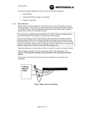
... that the outlets are power cords, but they do not draw power.) Plug a power cord from each low-voltage phase in the electrical panel for use with the Powerline MU Gateway only. While this is in the middle and post a caution sign that installation. Figure 7 Mass-metered installation Page 23 of...
... that the outlets are power cords, but they do not draw power.) Plug a power cord from each low-voltage phase in the electrical panel for use with the Powerline MU Gateway only. While this is in the middle and post a caution sign that installation. Figure 7 Mass-metered installation Page 23 of...
User Manual
Page 24
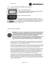
...Figure 9 Wiring the Panel Extender Pay careful attention to local code for conduit and wire size requirements. Once connected, if the product is connected. Use unused breakers if available. Refer to the "Signal Out" and Signal In" labels. The "Signal Out" ports are available. This may include...through the "Signal Out" ports, but the AC power cannot, so be sure to connect the newly created outlets to the enclosure, or using 4-core cable and cable glands. Extend four wires (each phase, remembering to four breaker panels simultaneously with local codes. At the subsequent breaker...
...Figure 9 Wiring the Panel Extender Pay careful attention to local code for conduit and wire size requirements. Once connected, if the product is connected. Use unused breakers if available. Refer to the "Signal Out" and Signal In" labels. The "Signal Out" ports are available. This may include...through the "Signal Out" ports, but the AC power cannot, so be sure to connect the newly created outlets to the enclosure, or using 4-core cable and cable glands. Extend four wires (each phase, remembering to four breaker panels simultaneously with local codes. At the subsequent breaker...
User Manual
Page 25
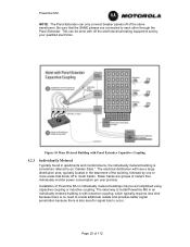
Powerline MU NOTE: The Panel Extender can be accomplished using capacitive coupling or inductive coupling. Figure 10 Mass Metered Building with inductive coupling, which typically requires less time because there is no need to create ...
Powerline MU NOTE: The Panel Extender can be accomplished using capacitive coupling or inductive coupling. Figure 10 Mass Metered Building with inductive coupling, which typically requires less time because there is no need to create ...
User Manual
Page 26
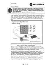
... the meter bank. Page 26 of electrical cables which may apply. Sometimes there will consist of the couplers. A typical termination cabinet will be a location to use proper safety gear, including properly rated electrical gloves and eyewear. Powerline MU Inductive Coupling WARNING! Install Powerline MU Inductive Couplers in the termination cabinet. The...
... the meter bank. Page 26 of electrical cables which may apply. Sometimes there will consist of the couplers. A typical termination cabinet will be a location to use proper safety gear, including properly rated electrical gloves and eyewear. Powerline MU Inductive Coupling WARNING! Install Powerline MU Inductive Couplers in the termination cabinet. The...

User Manual
Page 28
Use that coupler. Conductor/Coupler Chart Column A Conductor Size (American Wire Gauge) Column B Conductor Size (Metric Wire Gauge, mm2) Column C Approx Conductor Outer Diameter With Insulation (... Coupler Inner Diameter (mm) 31 31 31 31 31 25.4 25.4 25.4 25.4 25.4 19.4 19.4 19.4 19.4 19.4 19.4 14 14 14 14 Column F Motorola Part Number TBD* 0171486N21 0171486N23 0171486N22 Page 28 of the electric wire installed in the building. Powerline MU Inductive Coupler Sizes Column A lists the American...
Use that coupler. Conductor/Coupler Chart Column A Conductor Size (American Wire Gauge) Column B Conductor Size (Metric Wire Gauge, mm2) Column C Approx Conductor Outer Diameter With Insulation (... Coupler Inner Diameter (mm) 31 31 31 31 31 25.4 25.4 25.4 25.4 25.4 19.4 19.4 19.4 19.4 19.4 19.4 14 14 14 14 Column F Motorola Part Number TBD* 0171486N21 0171486N23 0171486N22 Page 28 of the electric wire installed in the building. Powerline MU Inductive Coupler Sizes Column A lists the American...

User Manual
Page 29
... determining the length needed • Rubber Grommets as shown in the bottom or side of bi-directional splitters needed (if feeding multiple cabinets). 4. If possible, use bi-directional splitters. Install conduit fitting in half, with standard FConnectors on the other F-Connector lead (from one half containing the insulated cable that will...
... determining the length needed • Rubber Grommets as shown in the bottom or side of bi-directional splitters needed (if feeding multiple cabinets). 4. If possible, use bi-directional splitters. Install conduit fitting in half, with standard FConnectors on the other F-Connector lead (from one half containing the insulated cable that will...
User Manual
Page 30
Be sure couplers do not slide. Ideal installation here is similar to use cable ties or rubber grommets to each of signal degradation. • The signal will not travel back through the 2nd floor transformer and through the ...). Try to the Individually Metered scenario, but with more than two splits because of these buildings have different electrical feeds into the building. If needed, use no more planning. If this is to be sure you get the internet connection to assure stability. 14. These situations require more than the preceding...
Be sure couplers do not slide. Ideal installation here is similar to use cable ties or rubber grommets to each of signal degradation. • The signal will not travel back through the 2nd floor transformer and through the ...). Try to the Individually Metered scenario, but with more than two splits because of these buildings have different electrical feeds into the building. If needed, use no more planning. If this is to be sure you get the internet connection to assure stability. 14. These situations require more than the preceding...
User Manual
Page 31
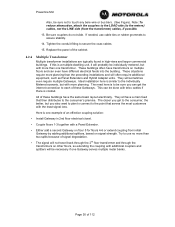
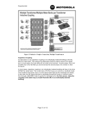
..., then through a SECOND meter to get to the individual units. Powerline MU Figure 13 Inductive Coupler Connection, Multiple Transformers Capacitive Coupling An ideal place to use capacitive coupling in an individually metered building is located in an individually metered building will not need to be done AFTER the meter bank.
..., then through a SECOND meter to get to the individual units. Powerline MU Figure 13 Inductive Coupler Connection, Multiple Transformers Capacitive Coupling An ideal place to use capacitive coupling in an individually metered building is located in an individually metered building will not need to be done AFTER the meter bank.


