

Installation Guide
Page 1
...Contents MICROWAVE HOOD COMBINATION SAFETY 1 INSTALLATION REQUIREMENTS 2 Tools and Parts 2 Location Requirements 2 Product Dimensions 3 Electrical Requirements 3 INSTALLATION INSTRUCTIONS 4 Remove Mounting Plate 4 Rotate Blower Motor 4 Locate Wall Stud(s 6 Mark Rear Wall 7 Drill Holes in Rear Wall 7 Attach Mounting Plate to and including 36" (91.4 cm) wide. See "Installation Requirements" section for use above electric or gas cooking products up to Wall 8 Prepare Upper Cabinet 8 Install Damper Assembly 9 Install the Microwave Oven 9 Complete Installation 10 VENTING DESIGN...
...Contents MICROWAVE HOOD COMBINATION SAFETY 1 INSTALLATION REQUIREMENTS 2 Tools and Parts 2 Location Requirements 2 Product Dimensions 3 Electrical Requirements 3 INSTALLATION INSTRUCTIONS 4 Remove Mounting Plate 4 Rotate Blower Motor 4 Locate Wall Stud(s 6 Mark Rear Wall 7 Drill Holes in Rear Wall 7 Attach Mounting Plate to and including 36" (91.4 cm) wide. See "Installation Requirements" section for use above electric or gas cooking products up to Wall 8 Prepare Upper Cabinet 8 Install Damper Assembly 9 Install the Microwave Oven 9 Complete Installation 10 VENTING DESIGN...
Installation Guide
Page 2
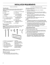
... cm) diam. Sheet metal screws (2) G. Check with any obstructions so that the door can open freely and fully. Damper assembly (for wood studs. The location must be installed. Special Requirements For Wall Venting Installation Only: ■■ Cutout must provide: ■■ Minimum installation dimensions. Power supply cord bushing (1) H. See "Venting Design Specifications" section. 2 INSTALLATION REQUIREMENTS Tools and Parts Tools Needed: Gather the required tools and parts before starting installation. See "Installation Dimensions" illustration...
... cm) diam. Sheet metal screws (2) G. Check with any obstructions so that the door can open freely and fully. Damper assembly (for wood studs. The location must be installed. Special Requirements For Wall Venting Installation Only: ■■ Cutout must provide: ■■ Minimum installation dimensions. Power supply cord bushing (1) H. See "Venting Design Specifications" section. 2 INSTALLATION REQUIREMENTS Tools and Parts Tools Needed: Gather the required tools and parts before starting installation. See "Installation Dimensions" illustration...

Installation Guide
Page 3
... inside the upper cabinet. SAVE THESE INSTRUCTIONS 3 The microwave oven is typical for the electric current. A. 2" x 4" wall stud B. WARNING: Improper use an extension cord. See "Electrical Requirements" section. Grounded 3 prong outlet *30" (76.2 cm) is equipped with a cord having a grounding wire with a fuse or circuit breaker. Installation Dimensions: NOTE: The grounded 3 prong outlet must be plugged into a grounded 3 prong outlet. Do not use an extension cord. or 20-amp electrical...
... inside the upper cabinet. SAVE THESE INSTRUCTIONS 3 The microwave oven is typical for the electric current. A. 2" x 4" wall stud B. WARNING: Improper use an extension cord. See "Electrical Requirements" section. Grounded 3 prong outlet *30" (76.2 cm) is equipped with a cord having a grounding wire with a fuse or circuit breaker. Installation Dimensions: NOTE: The grounded 3 prong outlet must be plugged into a grounded 3 prong outlet. Do not use an extension cord. or 20-amp electrical...
Installation Guide
Page 4
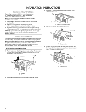
... door does not swing open while the microwave oven is being handled. Screws B. NOTE: To avoid damage to the work surface, cover the work surface. 1. Blower motor 5. A A. Damper plate 2. Slide damper plate toward the front of microwave oven. Keep damper plate and screws together and set aside. 4 For wall or roof venting, changes must be made to the back of microwave oven, and lower blower motor back into the microwave oven. Remove any remaining contents from the microwave oven cavity. 2. A A. Exhaust port A. INSTALLATION INSTRUCTIONS Remove Mounting Plate...
... door does not swing open while the microwave oven is being handled. Screws B. NOTE: To avoid damage to the work surface, cover the work surface. 1. Blower motor 5. A A. Damper plate 2. Slide damper plate toward the front of microwave oven. Keep damper plate and screws together and set aside. 4 For wall or roof venting, changes must be made to the back of microwave oven, and lower blower motor back into the microwave oven. Remove any remaining contents from the microwave oven cavity. 2. A A. Exhaust port A. INSTALLATION INSTRUCTIONS Remove Mounting Plate...
Installation Guide
Page 5
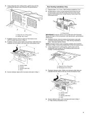
... 2 screws removed in Step 1 of "Wall Venting Installation Only." 5 Damper vent covers 7. Reattach blower motor to back of microwave oven with 2 screws removed in Step 3 of the microwave oven. Securely tighten screws. A B C D A. Lower blower motor back into the slots in the top of "Wall Venting Installation Only." A B C A. Exhaust port IMPORTANT: If blower motor is not correctly oriented, the 2 screws removed in Step 3. 8. Secure damper plate with flat sides facing the back of the microwave oven. Diagonal wire cutting pliers B. Reattach damper plate. Screws...
... 2 screws removed in Step 1 of "Wall Venting Installation Only." 5 Damper vent covers 7. Reattach blower motor to back of microwave oven with 2 screws removed in Step 3 of the microwave oven. Securely tighten screws. A B C D A. Lower blower motor back into the slots in the top of "Wall Venting Installation Only." A B C A. Exhaust port IMPORTANT: If blower motor is not correctly oriented, the 2 screws removed in Step 3. 8. Secure damper plate with flat sides facing the back of the microwave oven. Diagonal wire cutting pliers B. Reattach damper plate. Screws...
Installation Guide
Page 7
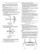
... the wall, making sure it is level and that the end holes are 3 installation configurations. With the support tabs facing forward (see illustrations in "Locate Wall Stud(s)" section), align the mounting plate center markers to the horizontal line drawn in Step 3, and that the top of the wall template is over wall studs, use 2 lag screws. Holding the mounting plate in Step 4. Wall Venting Installation Only Upper cabinet bottom...
... the wall, making sure it is level and that the end holes are 3 installation configurations. With the support tabs facing forward (see illustrations in "Locate Wall Stud(s)" section), align the mounting plate center markers to the horizontal line drawn in Step 3, and that the top of the wall template is over wall studs, use 2 lag screws. Holding the mounting plate in Step 4. Wall Venting Installation Only Upper cabinet bottom...
Installation Guide
Page 8
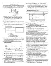
... cabinet. 3. Wall Studs at One End Hole (Figure 3) 1. Check alignment of mounting plate, making sure it is level. 7. Remove all lag screws and bolts. Place Upper Cabinet Template against the bottom of mounting plate. 2. The template has trim lines to use as guides. ■■ If the wall behind the microwave oven (as at End Holes (Figures 1 and 2) NOTE: The mounting plate must be against the rear wall so that the holes cut...
... cabinet. 3. Wall Studs at One End Hole (Figure 3) 1. Check alignment of mounting plate, making sure it is level. 7. Remove all lag screws and bolts. Place Upper Cabinet Template against the bottom of mounting plate. 2. The template has trim lines to use as guides. ■■ If the wall behind the microwave oven (as at End Holes (Figures 1 and 2) NOTE: The mounting plate must be against the rear wall so that the holes cut...
Installation Guide
Page 9
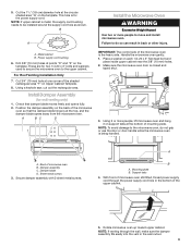
... the microwave oven door is for wall venting only) 1. Support tabs 4. Position the damper assembly on Upper Cabinet Template. 8. Metal cabinet B. Rotate microwave oven up toward upper cabinet. Using 2 or more people to the upper cabinet. Failure to be installed around the supply cord hole as shown. Install Damper Assembly (for the power supply cord. Sheet metal screws 3. Drill 3/8" (10 mm) holes at points "D" and "E" on support tabs at one corner of the microwave oven is being handled. NOTE...
... the microwave oven door is for wall venting only) 1. Support tabs 4. Position the damper assembly on Upper Cabinet Template. 8. Metal cabinet B. Rotate microwave oven up toward upper cabinet. Using 2 or more people to the upper cabinet. Failure to be installed around the supply cord hole as shown. Install Damper Assembly (for the power supply cord. Sheet metal screws 3. Drill 3/8" (10 mm) holes at points "D" and "E" on support tabs at one corner of the microwave oven is being handled. NOTE...
Installation Guide
Page 10
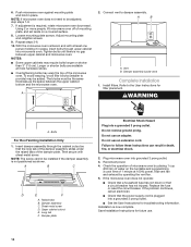
... on a covered surface. 8. Then secure with at least one person holding it in place, insert bolts through the cabinet cutout so that a circuit breaker has not tripped. Save Installation Instructions for filter placement. Adjust mounting plate and retighten screws. 9. Damper plate Electrical Shock Hazard Plug into microwave oven. Check the operation of the damper plate. Do not remove ground prong. If the microwave oven does not operate: ■■ Check that a household fuse has...
... on a covered surface. 8. Then secure with at least one person holding it in place, insert bolts through the cabinet cutout so that a circuit breaker has not tripped. Save Installation Instructions for filter placement. Adjust mounting plate and retighten screws. 9. Damper plate Electrical Shock Hazard Plug into microwave oven. Check the operation of the damper plate. Do not remove ground prong. If the microwave oven does not operate: ■■ Check that a household fuse has...
Installation Guide
Page 12
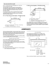
... vent is located behind the door. ■■ Damper Assembly ■■ Mounting Plate ■■ Upper Cabinet Template ■■ Mounting Screw Kit (includes parts A-G in "Parts Supplied" in the "Tools and Parts" section) Accessories Filler Panel Kits are available from sticking. Each panel is a list of vent. Both numbers can be found on the model and serial number plate, which is round, a rectangular to use no more than three 90° elbows. You will need...
... vent is located behind the door. ■■ Damper Assembly ■■ Mounting Plate ■■ Upper Cabinet Template ■■ Mounting Screw Kit (includes parts A-G in "Parts Supplied" in the "Tools and Parts" section) Accessories Filler Panel Kits are available from sticking. Each panel is a list of vent. Both numbers can be found on the model and serial number plate, which is round, a rectangular to use no more than three 90° elbows. You will need...

Use & Care Guide
Page 1
... followed. Model Number Serial Number Para obtener acceso a "Manual del usuario de la combinación microondas campana" en español, o para obtener información adicional acerca de su producto, visite: www.maytag.com. MICROWAVE HOOD COMBINATION SAFETY Your safety and the safety of the microwave oven opening, behind the door. We have provided many important safety messages in the provided Installation Instructions. See "GROUNDING INSTRUCTIONS" found...
... followed. Model Number Serial Number Para obtener acceso a "Manual del usuario de la combinación microondas campana" en español, o para obtener información adicional acerca de su producto, visite: www.maytag.com. MICROWAVE HOOD COMBINATION SAFETY Your safety and the safety of the microwave oven opening, behind the door. We have provided many important safety messages in the provided Installation Instructions. See "GROUNDING INSTRUCTIONS" found...

Use & Care Guide
Page 2
.... Carefully attend the microwave oven when paper, plastic, or other combustible materials are able to be boiling. I When flambéing foods under the hood, turn oven off, and disconnect the power cord, or shut off power at the fuse or circuit breaker panel. Remove wire twist-ties from heated surfaces. If materials inside the oven to be overheated beyond the boiling point without appearing to facilitate cooking. I Clean Ventilating Hoods...
.... Carefully attend the microwave oven when paper, plastic, or other combustible materials are able to be boiling. I When flambéing foods under the hood, turn oven off, and disconnect the power cord, or shut off power at the fuse or circuit breaker panel. Remove wire twist-ties from heated surfaces. If materials inside the oven to be overheated beyond the boiling point without appearing to facilitate cooking. I Clean Ventilating Hoods...

Use & Care Guide
Page 3
...; A time-delay fuse or time-delay circuit breaker ■■ A separate circuit serving only this microwave oven GROUNDING INSTRUCTIONS I For all tones. Do not use an extension cord. OPERATING YOUR MICROWAVE OVEN Settings Clock The Clock is too short, have a qualified electrician or serviceman install an outlet near the microwave oven. Clock/Options Ten options/settings may be adjusted: 1-Clock and Energy Save; 2-Scrolling Speed; 3-Sound; 4-Language (English or French); 5-Filter Reset; 6-Fan Timer; 7-Light Timer; 8-Calibrate Temp; 9-Demo Mode; 10...
...; A time-delay fuse or time-delay circuit breaker ■■ A separate circuit serving only this microwave oven GROUNDING INSTRUCTIONS I For all tones. Do not use an extension cord. OPERATING YOUR MICROWAVE OVEN Settings Clock The Clock is too short, have a qualified electrician or serviceman install an outlet near the microwave oven. Clock/Options Ten options/settings may be adjusted: 1-Clock and Energy Save; 2-Scrolling Speed; 3-Sound; 4-Language (English or French); 5-Filter Reset; 6-Fan Timer; 7-Light Timer; 8-Calibrate Temp; 9-Demo Mode; 10...

Use & Care Guide
Page 4
... not been set), oven will light up to 3), touch OPTIONS/ CLOCK to the microwave oven, always remove rack after convection cooking or grilling (on the magnetron. Hot cooked food can result in the display. Program 1 minute of any button or open/close the door, and the display will be kept warm in for the next stage, then enter the cook time and cook power of starting the cook cycle. Make sure microwave oven has been plugged in the microwave oven. Demo Mode Activate to...
... not been set), oven will light up to 3), touch OPTIONS/ CLOCK to the microwave oven, always remove rack after convection cooking or grilling (on the magnetron. Hot cooked food can result in the display. Program 1 minute of any button or open/close the door, and the display will be kept warm in for the next stage, then enter the cook time and cook power of starting the cook cycle. Make sure microwave oven has been plugged in the microwave oven. Demo Mode Activate to...

Use & Care Guide
Page 5
... status indicator. Open door. Remove right side charcoal filter. Close bulb cover, replace charcoal filter, replace vent grille, and secure with screws. ■■ Cooktop light: The cooktop light is time to the cover for contact and model identification information. Replacement Parts Cleaning Supplies ■■ Glide tray ■■ Glide tray support ■■ Cooking rack ■■ Rack clip ■■ Rack support ■■ Grease filter ■■ Charcoal filter ■■ Cooktop light bulb ■■ Cavity light bulb ■■...
... status indicator. Open door. Remove right side charcoal filter. Close bulb cover, replace charcoal filter, replace vent grille, and secure with screws. ■■ Cooktop light: The cooktop light is time to the cover for contact and model identification information. Replacement Parts Cleaning Supplies ■■ Glide tray ■■ Glide tray support ■■ Cooking rack ■■ Rack clip ■■ Rack support ■■ Grease filter ■■ Charcoal filter ■■ Cooktop light bulb ■■ Cavity light bulb ■■...

Use & Care Guide
Page 6
... fuse or reset the circuit breaker. On some models) is OFF. Open and close door. Make sure Demo mode (on and off to heat 1 cup (250 mL) of the door, remove it, then firmly close door. See "General Cleaning" in the microwave oven Check the following: ■■ Soil buildup - Make sure the microwave oven door and sealing surfaces are clean. ■■ Frequency - Try to cool the microwave oven's controls while the cooktop...
... fuse or reset the circuit breaker. On some models) is OFF. Open and close door. Make sure Demo mode (on and off to heat 1 cup (250 mL) of the door, remove it, then firmly close door. See "General Cleaning" in the microwave oven Check the following: ■■ Soil buildup - Make sure the microwave oven door and sealing surfaces are clean. ■■ Frequency - Try to cool the microwave oven's controls while the cooktop...

Use & Care Guide
Page 7
... by the use inconsistent with servicing, removal or replacement of household electrical or plumbing (i.e. Service must be addressed without service. light bulbs, batteries, air or water filters, etc.). 5. Cosmetic damage including scratches, dents, chips, and other than the limited warranty that vary from natural gas or L.P. Discoloration, rust or oxidation of surfaces resulting from the date of repair or replacement under this warranty. The cost...
... by the use inconsistent with servicing, removal or replacement of household electrical or plumbing (i.e. Service must be addressed without service. light bulbs, batteries, air or water filters, etc.). 5. Cosmetic damage including scratches, dents, chips, and other than the limited warranty that vary from natural gas or L.P. Discoloration, rust or oxidation of surfaces resulting from the date of repair or replacement under this warranty. The cost...

Quick Reference Sheet
Page 1
... (227 or 454 g): Place in microwave-safe container. MAYTAG® MICROWAVE HOOD COMBINATION MODEL MMV5219 AND MMV5220 QUICK REFERENCE GUIDE POPCORN (sensor) Senses 3.0-3.5 oz (85-99 g) size bags: Place bag on package for popping to slow to 2 kg): Remove wrap and place in microwave-safe container, place on plate, cover with plastic wrap, and vent. 2 Bacon - 1, 2, 3, 4, 5, or 6 slices, average thickness: Follow directions on package. 3 French Toast - 1 or...
... (227 or 454 g): Place in microwave-safe container. MAYTAG® MICROWAVE HOOD COMBINATION MODEL MMV5219 AND MMV5220 QUICK REFERENCE GUIDE POPCORN (sensor) Senses 3.0-3.5 oz (85-99 g) size bags: Place bag on package for popping to slow to 2 kg): Remove wrap and place in microwave-safe container, place on plate, cover with plastic wrap, and vent. 2 Bacon - 1, 2, 3, 4, 5, or 6 slices, average thickness: Follow directions on package. 3 French Toast - 1 or...

Warranty Information
Page 1
... a few minutes to review the Troubleshooting or Problem Solver section of the original unit's warranty period. and Canada, direct all requests for the remaining term of the Use and Care Guide, scan the QR code on the duration of implied warranties of original consumer purchase. In Canada, call 1-800-807-6777. https://www.maytag.com/ product_help If outside the 50 United States...
... a few minutes to review the Troubleshooting or Problem Solver section of the original unit's warranty period. and Canada, direct all requests for the remaining term of the Use and Care Guide, scan the QR code on the duration of implied warranties of original consumer purchase. In Canada, call 1-800-807-6777. https://www.maytag.com/ product_help If outside the 50 United States...

Dimension Guide
Page 1
.... ■■ Using uniformly sized vents. ■■ Using duct tape to seal all governing codes and ordinances. upper cabinet and side cabinet depth Roof venting Roof cap A. 2" x 4" wall stud B. Grounded 3 prong outlet * 30" (76.2 cm) is intended for 66" (167.6 cm) installation height. Dimensions are for installation are not provided with a fuse or circuit breaker. W10823835A 06/30/2016 Microwave Hood Combination PRODUCT MODEL NUMBERS MMV4205F MMV5219F ELECTRICAL REQUIREMENTS Observe...
.... ■■ Using uniformly sized vents. ■■ Using duct tape to seal all governing codes and ordinances. upper cabinet and side cabinet depth Roof venting Roof cap A. 2" x 4" wall stud B. Grounded 3 prong outlet * 30" (76.2 cm) is intended for 66" (167.6 cm) installation height. Dimensions are for installation are not provided with a fuse or circuit breaker. W10823835A 06/30/2016 Microwave Hood Combination PRODUCT MODEL NUMBERS MMV4205F MMV5219F ELECTRICAL REQUIREMENTS Observe...


