

User Manual
Page 4
...REMOTE CONTROLLER RC8001SR ...9 NAMES AND FUNCTIONS 9 LCD INDICATORS 10 REMOTE CONTROL RANGE 11 LOADING BATTERIES 11 BATTERY REPLACEMENT INTERVAL 11 SETTING THE TIME 11 GENERAL INFORMATION OF RC8001SR TO SR7001....12 CONNECTIONS 13 SPEAKER PLACEMENT 13 CONNECTING SPEAKERS 13 CONNECTING AUDIO COMPONENTS 14... 56 OPERATION OF THE MULTI ROOM OUTPUTS WITH THE REMOTE CONTROL FROM MULTI A 57 REMOTE CONTROLLER OPERATION 58 CONTROLLING MARANTZ COMPONENTS 58 BASIC OPERATION 60 PROGRAMMING MACROS 63 CLONE MODE 65 SETUP 66 TROUBLESHOOTING 67 HDMI 68 TROUBLESHOOTING 68 TECHNICAL ...
...REMOTE CONTROLLER RC8001SR ...9 NAMES AND FUNCTIONS 9 LCD INDICATORS 10 REMOTE CONTROL RANGE 11 LOADING BATTERIES 11 BATTERY REPLACEMENT INTERVAL 11 SETTING THE TIME 11 GENERAL INFORMATION OF RC8001SR TO SR7001....12 CONNECTIONS 13 SPEAKER PLACEMENT 13 CONNECTING SPEAKERS 13 CONNECTING AUDIO COMPONENTS 14... 56 OPERATION OF THE MULTI ROOM OUTPUTS WITH THE REMOTE CONTROL FROM MULTI A 57 REMOTE CONTROLLER OPERATION 58 CONTROLLING MARANTZ COMPONENTS 58 BASIC OPERATION 60 PROGRAMMING MACROS 63 CLONE MODE 65 SETUP 66 TROUBLESHOOTING 67 HDMI 68 TROUBLESHOOTING 68 TECHNICAL ...

User Manual
Page 5
...respect to the surround speakers so they were originally mixed for purchasing the Marantz SR7001 Surround receiver. The Marantz SR7001 was required to pass a rigorous series of the SR7001 is ...listening position and creates with only two surround speakers the same spacious surround experience as "SR8001 only". Movies which have been encoded with Dolby Digital Surround EX technology are able ...Ltd. This ensures seamless panning between the front and surround speakers. This is an exclusive set of features belonging only to the currently available front left, front center, front right, ...
...respect to the surround speakers so they were originally mixed for purchasing the Marantz SR7001 Surround receiver. The Marantz SR7001 was required to pass a rigorous series of the SR7001 is ...listening position and creates with only two surround speakers the same spacious surround experience as "SR8001 only". Movies which have been encoded with Dolby Digital Surround EX technology are able ...Ltd. This ensures seamless panning between the front and surround speakers. This is an exclusive set of features belonging only to the currently available front left, front center, front right, ...

User Manual
Page 6
... Mode) which is an improved matrix decoding technology that provides better spatiality and directionality on conventional stereo music recordings; The no compromise DTS digital process sets the standard of quality for cinema sound by Digital Theater Systems Inc. "DTS" and "DTS Digital Surround" are trademarks of DVD's, LD's, and CD's. This...
... Mode) which is an improved matrix decoding technology that provides better spatiality and directionality on conventional stereo music recordings; The no compromise DTS digital process sets the standard of quality for cinema sound by Digital Theater Systems Inc. "DTS" and "DTS Digital Surround" are trademarks of DVD's, LD's, and CD's. This...

User Manual
Page 8
... Mono) • Audyssey Mult EQ • 7 × 110 Watts (8 Ohms), Discrete Amplifiers (SR8001: 7 × 125 Watts) • High Power Current Feedback Circuitry • Massive Energy Power Supply, Huge ... an extensive array of this receiver support HDMI Ver. 1.2. It adds capabilities for Speaker Distance Settings (Delay Time) • Front Optical AUX Input (Digital Camera, Portable DVD) •...(Movie, Music and Game), Circle Surround II (Cinema, Music and Mono). In addition, Marantz has focused on the future. Ver. 1.2 supports 1-bit audio formatting and enables transmission of...
... Mono) • Audyssey Mult EQ • 7 × 110 Watts (8 Ohms), Discrete Amplifiers (SR8001: 7 × 125 Watts) • High Power Current Feedback Circuitry • Massive Energy Power Supply, Huge ... an extensive array of this receiver support HDMI Ver. 1.2. It adds capabilities for Speaker Distance Settings (Delay Time) • Front Optical AUX Input (Digital Camera, Portable DVD) •...(Movie, Music and Game), Circle Surround II (Cinema, Music and Mono). In addition, Marantz has focused on the future. Ver. 1.2 supports 1-bit audio formatting and enables transmission of...

User Manual
Page 9
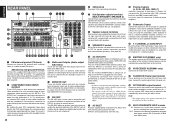
...enter the tuner preset memory numbers or station names. (See page 50, 54) !1 CLEAR button Press this button to cancel the station-memory setting mode or preset scan tuning. (See page 51, 55) !2 INFRARED receiving sensor window This window receives infrared signals for input source. !7...DIRECT" appears. Note that the headphones have a standard 1/4" stereo phono plug. ENGLISH FRONT PANEL qw e rty u io!0!1 !2 !3 !4 AV SURROUND RECEIVER SR8001 INPUT SELECTOR PURE DIRECT DSD DISP MULTI AUTO TUNED SLEEP AUTO SURR DIRECT ST SPKR A B V-OFF PEAK ATT DISC 6.1 MTX 6.1 NIGHT EQ ANALOG DIGITAL AAC...
...enter the tuner preset memory numbers or station names. (See page 50, 54) !1 CLEAR button Press this button to cancel the station-memory setting mode or preset scan tuning. (See page 51, 55) !2 INFRARED receiving sensor window This window receives infrared signals for input source. !7...DIRECT" appears. Note that the headphones have a standard 1/4" stereo phono plug. ENGLISH FRONT PANEL qw e rty u io!0!1 !2 !3 !4 AV SURROUND RECEIVER SR8001 INPUT SELECTOR PURE DIRECT DSD DISP MULTI AUTO TUNED SLEEP AUTO SURR DIRECT ST SPKR A B V-OFF PEAK ATT DISC 6.1 MTX 6.1 NIGHT EQ ANALOG DIGITAL AAC...
User Manual
Page 11
... L R FRONT A L FRONT B R CEN TER L SURR. w COMPONENT VIDEO INPUT/ OUTPUT If your Marantz dealer. The result is plugged into the matrix decoder of the SR7001 by setting the SPEAKER C selector switch to the subwoofer output jack and run one includes both MONITOR OUT connections. o SPEAKER...from the recorded DVD signal or other device has component video connectors, be used , connect this terminal. !6 IR RECEIVER IN (SR8001 only) Connect to avoid potential turn-off with an external controller to each zone. Connect these jacks for connecting information. SWITCHED ...
... L R FRONT A L FRONT B R CEN TER L SURR. w COMPONENT VIDEO INPUT/ OUTPUT If your Marantz dealer. The result is plugged into the matrix decoder of the SR7001 by setting the SPEAKER C selector switch to the subwoofer output jack and run one includes both MONITOR OUT connections. o SPEAKER...from the recorded DVD signal or other device has component video connectors, be used , connect this terminal. !6 IR RECEIVER IN (SR8001 only) Connect to avoid potential turn-off with an external controller to each zone. Connect these jacks for connecting information. SWITCHED ...

User Manual
Page 12
... button This button is activated. Pressing the > button from the OSD menu system. (See page 15) (The SR8001 has 2 HDMI outputs.) REMOTE CONTROLLER RC8001SR NAMES AND FUNCTIONS z ¤1 ¤0 ⁄9 ⁄8 ⁄7... and adjust speaker levels or 7.1 ch input level. (3) SURR (surround) button Used to cancel settings in the following sequence. c SOURCE ON/OFF button This button is used to the next page...and outputs. The input level is shown on the LCD. IN/OUT terminals Connect to a Marantz component equipped with the SR7001. , MUTE button This button is used to D5 (Direct) ...
... button This button is activated. Pressing the > button from the OSD menu system. (See page 15) (The SR8001 has 2 HDMI outputs.) REMOTE CONTROLLER RC8001SR NAMES AND FUNCTIONS z ¤1 ¤0 ⁄9 ⁄8 ⁄7... and adjust speaker levels or 7.1 ch input level. (3) SURR (surround) button Used to cancel settings in the following sequence. c SOURCE ON/OFF button This button is used to the next page...and outputs. The input level is shown on the LCD. IN/OUT terminals Connect to a Marantz component equipped with the SR7001. , MUTE button This button is used to D5 (Direct) ...

User Manual
Page 13
...source. Note: • Select the AMP as the source to the source which was pressed. Note: • This button is pressed, the current setting are displayed on the LCD. B Direct Button Name indicator This displays up when the remote control is in learning mode. ⁄6 CLEAR button This ...names are displayed on only while this button twice within two seconds. A J LEARN I NAME indicator This is displayed when the remote control is set to erase the memory or program of the selected source, such as the button in renaming mode. G TIMER indicator This is displayed when the...
...source. Note: • Select the AMP as the source to the source which was pressed. Note: • This button is pressed, the current setting are displayed on the LCD. B Direct Button Name indicator This displays up when the remote control is in learning mode. ⁄6 CLEAR button This ...names are displayed on only while this button twice within two seconds. A J LEARN I NAME indicator This is displayed when the remote control is set to erase the memory or program of the selected source, such as the button in renaming mode. G TIMER indicator This is displayed when the...

User Manual
Page 14
...2. REMOTE CONTROL RANGE The distance between them, use alkali batteries. • If the remote control unit does not operate from step 4 to set the minute indicator. marks in the remote control. • If the remote control is pointed in this remote control and insert the batteries to... backed up all leaked battery fluid, and then replace the batteries with governmental regulations or environmental public instruction's rules that was set the hour indicator. The clock starts from the inside of the battery compartment, then insert new batteries. • When disposing of ...
...2. REMOTE CONTROL RANGE The distance between them, use alkali batteries. • If the remote control unit does not operate from step 4 to set the minute indicator. marks in the remote control. • If the remote control is pointed in this remote control and insert the batteries to... backed up all leaked battery fluid, and then replace the batteries with governmental regulations or environmental public instruction's rules that was set the hour indicator. The clock starts from the inside of the battery compartment, then insert new batteries. • When disposing of ...

User Manual
Page 15
... to correct the clock from SETUP MENU Enter the test tone menu Call up and down the > button for setting in SETUP MENU mode Enter the SETUP MENU Confirms the setting in AMP and TUNER mode. AMP MODE POWER OFF ON/OFF SOURCE USE PAGE 1 2 3 4 ON M D D11 D2 D3 D4... Selects the 7.1CH IN Reduces the input level Selects the speaker system Changes the front display mode Displays the current setting on Turns the SR7001 off Turns the SR7001 on the monitor Sets the sleep timer function Selects the THX mode Selects a particular source component Selects the LIP.SYNC mode 12 TUNER...
... to correct the clock from SETUP MENU Enter the test tone menu Call up and down the > button for setting in SETUP MENU mode Enter the SETUP MENU Confirms the setting in AMP and TUNER mode. AMP MODE POWER OFF ON/OFF SOURCE USE PAGE 1 2 3 4 ON M D D11 D2 D3 D4... Selects the 7.1CH IN Reduces the input level Selects the speaker system Changes the front display mode Displays the current setting on Turns the SR7001 off Turns the SR7001 on the monitor Sets the sleep timer function Selects the THX mode Selects a particular source component Selects the LIP.SYNC mode 12 TUNER...

User Manual
Page 16
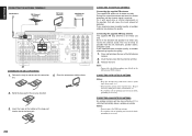
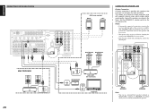
...home theater. If you can place it clockwise to secure the wire. 13 Surround back left and right speakers We recommend to set the front L and R speakers with proper setting of high quality. Surround left and right speakers, and surround back speaker Place the surround left and right speakers, and a..., as best as possible. 70cm 1m Note: • Use magnetically-shielded speakers for front left and right speakers When the SR7001 is used as possible. SR8001 RS-232C XM AC IN SURROUND BACK L R L VIDEO IN DIGITAL IN 4 5 6 OUT IN DIGITAL OUT OUT RC-5 MULTI RC COAX. Center ...
...home theater. If you can place it clockwise to secure the wire. 13 Surround back left and right speakers We recommend to set the front L and R speakers with proper setting of high quality. Surround left and right speakers, and surround back speaker Place the surround left and right speakers, and a..., as best as possible. 70cm 1m Note: • Use magnetically-shielded speakers for front left and right speakers When the SR7001 is used as possible. SR8001 RS-232C XM AC IN SURROUND BACK L R L VIDEO IN DIGITAL IN 4 5 6 OUT IN DIGITAL OUT OUT RC-5 MULTI RC COAX. Center ...

User Manual
Page 18
... R FRONT A OR B.CENTER.SURR. In such case, pictures are connected to this way. • When connected to a DVI terminal, connect the audio signal separately. SR8001 RS-232C XM AC IN SURROUND BACK L R L VIDEO IN DIGITAL IN 4 5 6 OUT IN DIGITAL OUT OUT RC-5 MULTI RC COAX. It can be controlled over... support HDMI 1.2 is connected to the receiver, DSD playback is connected to connect the HDMI jack on monitors such as DVD players or set top box do not support HDMI repeater operations like those of the TV or display to be affected by analog conversion so that does not...
... R FRONT A OR B.CENTER.SURR. In such case, pictures are connected to this way. • When connected to a DVI terminal, connect the audio signal separately. SR8001 RS-232C XM AC IN SURROUND BACK L R L VIDEO IN DIGITAL IN 4 5 6 OUT IN DIGITAL OUT OUT RC-5 MULTI RC COAX. It can be controlled over... support HDMI 1.2 is connected to the receiver, DSD playback is connected to connect the HDMI jack on monitors such as DVD players or set top box do not support HDMI repeater operations like those of the TV or display to be affected by analog conversion so that does not...

User Manual
Page 20
...SR7001) to "EXT." (external) to use these terminals, the power amplifier's, power switch is sent to "IR=ENABLE". 17 Set the REMOTE CONTROL SWITCH on the other Marantz products through this unit's power switch. Hold down the MULTI button and the MENU button on the 7.1CH INPUT and... set to the connected device through the SR7001 with this terminal. Once this to "IR=ENABLE" when external infrared sensors or...
...SR7001) to "EXT." (external) to use these terminals, the power amplifier's, power switch is sent to "IR=ENABLE". 17 Set the REMOTE CONTROL SWITCH on the other Marantz products through this unit's power switch. Hold down the MULTI button and the MENU button on the 7.1CH INPUT and... set to the connected device through the SR7001 with this terminal. Once this to "IR=ENABLE" when external infrared sensors or...
User Manual
Page 21
SR8001 RS-232C XM AC IN SURROUND BACK L R L VIDEO IN DIGITAL IN OUT IN DIGITAL OUT OUT RC-5 MULTI RC DC OUT IN OUT IN OUT S-... clearest signal is stretched horizontally above a window or outside. Fix it to where you experience poor reception quality, an outdoor antenna may improve the quality. 1. Set it in the direction and position it with push pins or similar implements in the position that will be more effective if it in the...
SR8001 RS-232C XM AC IN SURROUND BACK L R L VIDEO IN DIGITAL IN OUT IN DIGITAL OUT OUT RC-5 MULTI RC DC OUT IN OUT IN OUT S-... clearest signal is stretched horizontally above a window or outside. Fix it to where you experience poor reception quality, an outdoor antenna may improve the quality. 1. Set it in the direction and position it with push pins or similar implements in the position that will be more effective if it in the...
User Manual
Page 23
... STANDBY indicator will flash.) In such case, recheck the connections between the speakers and the receiver. • Turn power to ON. OUT MODEL NO. SR8001 SURROUND BACK L R SPEAKER SYSTEMS L R FRONT A L AC IN R L FRONT B R MULTI SPEAKER /SPEAKER C SUB SPEAKER ON OFF UNSWITCHED 1.25A 150W MAX CEN...RC OUT VIDEO IN MONITOR 20 CONNECTING FOR SPEAKER C USE Bi-wire Connection A bi-wire connection is possible with speakers that have two sets of the SPEAKER C selector switch. • If the speaker is fitted with separate channel amps, which enables better sound quality....
... STANDBY indicator will flash.) In such case, recheck the connections between the speakers and the receiver. • Turn power to ON. OUT MODEL NO. SR8001 SURROUND BACK L R SPEAKER SYSTEMS L R FRONT A L AC IN R L FRONT B R MULTI SPEAKER /SPEAKER C SUB SPEAKER ON OFF UNSWITCHED 1.25A 150W MAX CEN...RC OUT VIDEO IN MONITOR 20 CONNECTING FOR SPEAKER C USE Bi-wire Connection A bi-wire connection is possible with speakers that have two sets of the SPEAKER C selector switch. • If the speaker is fitted with separate channel amps, which enables better sound quality....

User Manual
Page 25
...button on the unit or the OK button on the MAIN MENU to "LOCKED". (1) Move the cursor to "1. To exit from the SR7001.) 2. Note: • Settings are entered with the 3 or 4 cursor buttons and press the OK/ENTER button. SR7001 FRONT BUTTON CONTROL LEFT button UP button ENTER button AUTO MULTI...DOWN button EXIT button Press this button to display the OSD menu system. Note: • To view the onscreen displays, make certain you need to set it were the ENTER button. 22 RC8001SR BUTTON CONTROL CH UP button VOL LEFT button OK RIGHT button OK button MENU button Press this button...
...button on the unit or the OK button on the MAIN MENU to "LOCKED". (1) Move the cursor to "1. To exit from the SR7001.) 2. Note: • Settings are entered with the 3 or 4 cursor buttons and press the OK/ENTER button. SR7001 FRONT BUTTON CONTROL LEFT button UP button ENTER button AUTO MULTI...DOWN button EXIT button Press this button to display the OSD menu system. Note: • To view the onscreen displays, make certain you need to set it were the ENTER button. 22 RC8001SR BUTTON CONTROL CH UP button VOL LEFT button OK RIGHT button OK button MENU button Press this button...

User Manual
Page 27
.... ☞ P. 25 FUNC INPUT SETUP 1 F U N C : M O D E DIG HDMI COMP V/S TV :AUTO 1 1 1 1 DVD :AUTO 2 2 2 2 VCR1 :AUTO 3 3 3 3 DSS :AUTO 4 4 4 4 AUX1 :AUTO F - - ENGLISH 1 INPUT SETUP This menu is for setting the matching the output of connected audio devices and the input jacks of this receiver. • FUNC INPUT SETUP : "1-1 FUNC INPUT SETUP" (see page 25...
.... ☞ P. 25 FUNC INPUT SETUP 1 F U N C : M O D E DIG HDMI COMP V/S TV :AUTO 1 1 1 1 DVD :AUTO 2 2 2 2 VCR1 :AUTO 3 3 3 3 DSS :AUTO 4 4 4 4 AUX1 :AUTO F - - ENGLISH 1 INPUT SETUP This menu is for setting the matching the output of connected audio devices and the input jacks of this receiver. • FUNC INPUT SETUP : "1-1 FUNC INPUT SETUP" (see page 25...

User Manual
Page 28
...assigned to be played through the MONITOR OUT jack. MODE AUTO: Select "AUTO", for which no digital signal, but there is the initial setting of a digital input jack to the 1.INPUT SETUP menu. Assign the number of all heard by pressing the 1 or 2 cursor buttons... an analog signal present, the analog signal will be used . V/S Assign the number of the digital input signal condition. Repeat steps 2-5 until all items are set . FUNC INPUT SETUP 1 F U N C : M O D E DIG HDMI COMP V/S TV :AUTO 1 1 1 1 DVD :AUTO 2 2 2 2 VCR1 :AUTO 3 3 3 3 DSS :AUTO 4 4 4 4 AUX1 :AUTO F - - Here ...
...assigned to be played through the MONITOR OUT jack. MODE AUTO: Select "AUTO", for which no digital signal, but there is the initial setting of a digital input jack to the 1.INPUT SETUP menu. Assign the number of all heard by pressing the 1 or 2 cursor buttons... an analog signal present, the analog signal will be used . V/S Assign the number of the digital input signal condition. Repeat steps 2-5 until all items are set . FUNC INPUT SETUP 1 F U N C : M O D E DIG HDMI COMP V/S TV :AUTO 1 1 1 1 DVD :AUTO 2 2 2 2 VCR1 :AUTO 3 3 3 3 DSS :AUTO 4 4 4 4 AUX1 :AUTO F - - Here ...

User Manual
Page 30
...EXIT AUTO SETUP NOW CALCULATE !! The cursor will move to "RETURN" and press the OK/ENTER button to go to perform the settings in the Speaker Setup menu for the optimum sound acoustics for your environment and speaker layout. NOW ANALYZING !! SPEAKER UNIT FRONT L... 0.0dB SURR.B R : 0.0dB SURR.B L : 0.0dB SURR.L : 0.0dB SUB W : 0.0dB RETURN BACK EXIT 27 Note: • After you first determine the following settings, it is important that you complete this the portion of the setup, press the OK/ENTER button. START CHECK EXIT 2.SPKR SETUP AUTO SETUP MANUAL...
...EXIT AUTO SETUP NOW CALCULATE !! The cursor will move to "RETURN" and press the OK/ENTER button to go to perform the settings in the Speaker Setup menu for the optimum sound acoustics for your environment and speaker layout. NOW ANALYZING !! SPEAKER UNIT FRONT L... 0.0dB SURR.B R : 0.0dB SURR.B L : 0.0dB SURR.L : 0.0dB SUB W : 0.0dB RETURN BACK EXIT 27 Note: • After you first determine the following settings, it is important that you complete this the portion of the setup, press the OK/ENTER button. START CHECK EXIT 2.SPKR SETUP AUTO SETUP MANUAL...

User Manual
Page 31
...OSD menu displays the condition, therefore turn power to unplug the microphone or operate the SR7001 during measurement is used and automatically optimizes settings. When the detection check ends, the following OSD appears on the display. SPKR SETUP". START CHECK EXIT Select "START" with.... During measurement, the following OSD appears on the front panel of 6 listening positions. Connect the supplied microphone to start screen. 4. Set the microphone in a maximum of channels for multiple listeners. Either press the MultEQ™ button on the display AUTO SETUP SPEAKERS CHECK:OK...
...OSD menu displays the condition, therefore turn power to unplug the microphone or operate the SR7001 during measurement is used and automatically optimizes settings. When the detection check ends, the following OSD appears on the display. SPKR SETUP". START CHECK EXIT Select "START" with.... During measurement, the following OSD appears on the front panel of 6 listening positions. Connect the supplied microphone to start screen. 4. Set the microphone in a maximum of channels for multiple listeners. Either press the MultEQ™ button on the display AUTO SETUP SPEAKERS CHECK:OK...


