
Owners Manual
Page 2
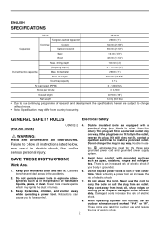
.... Replace damaged cords immediately. bit diameter 25 mm (1") Max. Failure to country. Keep bystanders, children, and visitors away while operating a power tool. Do not abuse the cord. ENGLISH SPECIFICATIONS Model HR2432 Tungsten-carbide tipped bit 25 mm (1") Concrete Core bit 54 mm (2-1/8") Capacities Diamond core bit 65 mm (2-1/2") Steel 13 mm (1/2") Wood...
.... Replace damaged cords immediately. bit diameter 25 mm (1") Max. Failure to country. Keep bystanders, children, and visitors away while operating a power tool. Do not abuse the cord. ENGLISH SPECIFICATIONS Model HR2432 Tungsten-carbide tipped bit 25 mm (1") Concrete Core bit 54 mm (2-1/8") Capacities Diamond core bit 65 mm (2-1/2") Steel 13 mm (1/2") Wood...
Owners Manual
Page 3
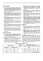
... keys or wrenches before using an extension cord, be repaired. 18. Use clamps or other untrained persons. Tools are NOT eye protection. When servicing a tool, use tool while tired or under the influence of children and other practical way to secure and support the workpiece to ... Make sure your model. Table 1: Minimum gage for misalignment or binding of moving parts, breakage of inattention while operating power tools may affect the tools operation. Stay alert, watch what you are recommended by hand or against your product will cause a drop in line voltage ...
... keys or wrenches before using an extension cord, be repaired. 18. Use clamps or other untrained persons. Tools are NOT eye protection. When servicing a tool, use tool while tired or under the influence of children and other practical way to secure and support the workpiece to ... Make sure your model. Table 1: Minimum gage for misalignment or binding of moving parts, breakage of inattention while operating power tools may affect the tools operation. Stay alert, watch what you are recommended by hand or against your product will cause a drop in line voltage ...
Owners Manual
Page 4
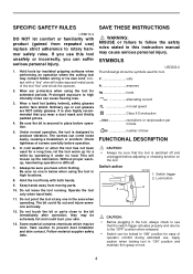
...metal parts of blow FUNCTIONAL DESCRIPTION CAUTION: • Always be sure that the switch trigger actuates properly and returns to see that the tool is also highly recommended that you wear a dust mask and thickly padded gloves. 4. Keep hands away from repeated use) replace strict...manual may be toxic. Do not touch the bit or parts close to prevent dust inhalation and skin contact. Apply caution when locking tool in the area when operating. Switch trigger 2. Check tightness of operator comfort during extended use. Switch action 001292 1. SPECIFIC SAFETY RULES ...
...metal parts of blow FUNCTIONAL DESCRIPTION CAUTION: • Always be sure that the switch trigger actuates properly and returns to see that the tool is also highly recommended that you wear a dust mask and thickly padded gloves. 4. Keep hands away from repeated use) replace strict...manual may be toxic. Do not touch the bit or parts close to prevent dust inhalation and skin contact. Apply caution when locking tool in the area when operating. Switch trigger 2. Check tightness of operator comfort during extended use. Switch action 001292 1. SPECIFIC SAFETY RULES ...

Owners Manual
Page 5
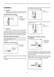
... torque limiter to the symbol. For continuous operation, pull the switch trigger and then push in one of rotation before the tool stops may damage the tool. • When you cannot push in the hole. Switch trigger A 2. Rotation only 003575 1. Rotation only 1 For drilling...switch action 001293 1. Rotation with hammering 1 2 003573 1. Torque limiter The torque limiter will stop . Reversing switch lever 1 B 2 This tool has a reversing switch to stop the tool from the output shaft. Use a twist drill bit or wood bit. Use a tungsten-carbide tipped bit. To start the...
... torque limiter to the symbol. For continuous operation, pull the switch trigger and then push in one of rotation before the tool stops may damage the tool. • When you cannot push in the hole. Switch trigger A 2. Rotation only 003575 1. Rotation only 1 For drilling...switch action 001293 1. Rotation with hammering 1 2 003573 1. Torque limiter The torque limiter will stop . Reversing switch lever 1 B 2 This tool has a reversing switch to stop the tool from the output shaft. Use a twist drill bit or wood bit. Use a tungsten-carbide tipped bit. To start the...
Owners Manual
Page 6
...Bit 1 2. iary handle) 3 2 1 After installing, always make sure that the bit is securely held in between the protrusions on the tool. Installing or removing the bit 001296 1. Depress the lock button and rotate the action mode changing knob to ensure operating safety. Tighten 2. This...out. 005875 1. Loosen 3. The bit can be secured at the desired position. ASSEMBLY CAUTION: • Always be sure that the tool is switched off and unplugged before installing the bit. Bit grease (optional accessory) Coat the bit shank head beforehand with a small amount...
...Bit 1 2. iary handle) 3 2 1 After installing, always make sure that the bit is securely held in between the protrusions on the tool. Installing or removing the bit 001296 1. Depress the lock button and rotate the action mode changing knob to ensure operating safety. Tighten 2. This...out. 005875 1. Loosen 3. The bit can be secured at the desired position. ASSEMBLY CAUTION: • Always be sure that the tool is switched off and unplugged before installing the bit. Bit grease (optional accessory) Coat the bit shank head beforehand with a small amount...

Owners Manual
Page 7
... side grip. Secure the dust bag by turning it clockwise at the position where the depth gauge strikes against the bottom of the tool. Depth gauge 1 Installing dust extractor attachment 005880 1 1. Coupling rod B A 3 When drilling without dust scattered around in the work... (9/16") Dust cup 9 12 mm (15/32") - 16 mm (5/8") 1 2 Keeping the angle of the interference between the attachment and the tool. Accordingly, do your work site. The coupling rod can be installed on yourself when performing overhead drilling operations. Coupling hole 3. Loosen the side grip and...
... side grip. Secure the dust bag by turning it clockwise at the position where the depth gauge strikes against the bottom of the tool. Depth gauge 1 Installing dust extractor attachment 005880 1 1. Coupling rod B A 3 When drilling without dust scattered around in the work... (9/16") Dust cup 9 12 mm (15/32") - 16 mm (5/8") 1 2 Keeping the angle of the interference between the attachment and the tool. Accordingly, do your work site. The coupling rod can be installed on yourself when performing overhead drilling operations. Coupling hole 3. Loosen the side grip and...

Owners Manual
Page 8
... dust or particles to the desired drilling depth of the dust extractor attachment. 005884 1. Accordingly, clean out the dust bag from the tool. Clamping screw 1 In drilling operation, hold the tool so that the stopper could slide on the depth gauge of dust extracting power. Depth adjustment 005885 1. NOTE: • Any space...
... dust or particles to the desired drilling depth of the dust extractor attachment. 005884 1. Accordingly, clean out the dust bag from the tool. Clamping screw 1 In drilling operation, hold the tool so that the stopper could slide on the depth gauge of dust extracting power. Depth adjustment 005885 1. NOTE: • Any space...
Owners Manual
Page 9
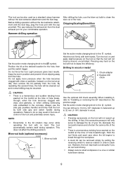
... the hole becomes clogged with the cap provided. Always use the blow-out bulb to reverse rotation in wood or metal 004223 1. The tool automatically centers itself during operations. Keyless drill chuck 2 Use the optional drill chuck assembly. You can drill up to "Installing or removing ...bit rotation may be resumed. Chipping/Scaling/Demolition 005890 Set the action mode changing knob to the symbol. Do not force the tool. Hold the tool firmly with no load. By repeating this excessive pressure will only serve to 32 mm (1-1/4") diameter in position and prevent it from...
... the hole becomes clogged with the cap provided. Always use the blow-out bulb to reverse rotation in wood or metal 004223 1. The tool automatically centers itself during operations. Keyless drill chuck 2 Use the optional drill chuck assembly. You can drill up to "Installing or removing ...bit rotation may be resumed. Chipping/Scaling/Demolition 005890 Set the action mode changing knob to the symbol. Do not force the tool. Hold the tool firmly with no load. By repeating this excessive pressure will only serve to 32 mm (1-1/4") diameter in position and prevent it from...
Owners Manual
Page 10
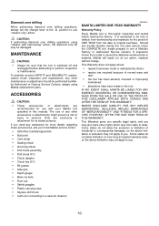
... • repairs have other rights which vary from workmanship and materials for connecting to a vacuum cleaner) EN0006-1 MAKITA LIMITED ONE YEAR WARRANTY Warranty Policy Every Makita tool is warranted to persons. If you need any other accessories or attachments might present a risk of original purchase....repairs, carbon brush inspection and replacement, any assistance for more details regarding these accessories, ask your Makita tool specified in this one year period, return the COMPLETE tool, freight prepaid, to one of defects from state to you may not apply to use with ...
... • repairs have other rights which vary from workmanship and materials for connecting to a vacuum cleaner) EN0006-1 MAKITA LIMITED ONE YEAR WARRANTY Warranty Policy Every Makita tool is warranted to persons. If you need any other accessories or attachments might present a risk of original purchase....repairs, carbon brush inspection and replacement, any assistance for more details regarding these accessories, ask your Makita tool specified in this one year period, return the COMPLETE tool, freight prepaid, to one of defects from state to you may not apply to use with ...
Parts Breakdown
Page 2
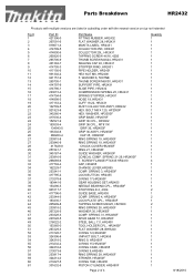
...HR2450F CHUCK COVER,HR2450F RING 21, HR2450F GUIDE WASHER, HR2450F CONICAL COMP. SPRING 31, HR2450F SPUR GEAR 51, HR2450F STEEL BALL 7.0, HR2400 TOOL HOLDER CPL., HR2450F FLAT WASHER 28, BHR240 O RING 12,HR2450F .IMPACT BOLT, HR2455 RING 9, HR2450F O RING 15,HR2450F O RING ... 216022-2 153365-0 267229-3 213128-7 324396-8 324218-2 213232-2 324216-6 213073-6 233917-4 324214-0 213227-5 331632-5 Part Name FITTING RUBBER, HR2432 FLAT WASHER 28, HR2431 MAKITA LABEL, HR2431 COLLECTOR 25R, HR2431 COLLECTOR 25L, HR2431 TAPPING SCREW 4X16, 420S THUMB SCREW M4X24, HR2431 SEALING CAP 40, HR2431 STOPPER ...
...HR2450F CHUCK COVER,HR2450F RING 21, HR2450F GUIDE WASHER, HR2450F CONICAL COMP. SPRING 31, HR2450F SPUR GEAR 51, HR2450F STEEL BALL 7.0, HR2400 TOOL HOLDER CPL., HR2450F FLAT WASHER 28, BHR240 O RING 12,HR2450F .IMPACT BOLT, HR2455 RING 9, HR2450F O RING 15,HR2450F O RING ... 216022-2 153365-0 267229-3 213128-7 324396-8 324218-2 213232-2 324216-6 213073-6 233917-4 324214-0 213227-5 331632-5 Part Name FITTING RUBBER, HR2432 FLAT WASHER 28, HR2431 MAKITA LABEL, HR2431 COLLECTOR 25R, HR2431 COLLECTOR 25L, HR2431 TAPPING SCREW 4X16, 420S THUMB SCREW M4X24, HR2431 SEALING CAP 40, HR2431 STOPPER ...

Flyer (English)
Page 1
... continuous operation DURABILITY Adjustable dust bag and elbow-shaped dust nozzle is secured and aligned close to the tool for longer life and increased dust efficiency ACCURACY Hammering with Rotation Rotation Only Chisel Angle Setting Hammer Only Model HR2432 3-mode switch for "rotation only," "hammering with 40 different locking positions DUST COLLECTION
... continuous operation DURABILITY Adjustable dust bag and elbow-shaped dust nozzle is secured and aligned close to the tool for longer life and increased dust efficiency ACCURACY Hammering with Rotation Rotation Only Chisel Angle Setting Hammer Only Model HR2432 3-mode switch for "rotation only," "hammering with 40 different locking positions DUST COLLECTION

Flyer (English)
Page 2
...Code 1" 1/2'' 1-1/4" 0 - 1,000 RPM 0 - 4,500 6.7 16" 6.6 lbs. 16.5 lbs. 2 088381-06133-9 Model HR2432 Accessories Thruster® Carbide-Tipped Bits Modular Thin Wall Core Bit System Hammer Steel I Thruster Style carbide tip penetrates on contact and plows... Makita U.S.A., 14930 Northam St., La Mirada, CA 90638 All specifications subject to 4" diameter I Designed for long lasting performance I Strength and surface hardness maximize life I From 1" to change without prior notice. RHF-0605-7.5M MA-0353-05 For more information, call 1-800-4MAKITA. impact energy (1.6 ft.lbs.) I Tool ...
...Code 1" 1/2'' 1-1/4" 0 - 1,000 RPM 0 - 4,500 6.7 16" 6.6 lbs. 16.5 lbs. 2 088381-06133-9 Model HR2432 Accessories Thruster® Carbide-Tipped Bits Modular Thin Wall Core Bit System Hammer Steel I Thruster Style carbide tip penetrates on contact and plows... Makita U.S.A., 14930 Northam St., La Mirada, CA 90638 All specifications subject to 4" diameter I Designed for long lasting performance I Strength and surface hardness maximize life I From 1" to change without prior notice. RHF-0605-7.5M MA-0353-05 For more information, call 1-800-4MAKITA. impact energy (1.6 ft.lbs.) I Tool ...
Technical Reference
Page 1
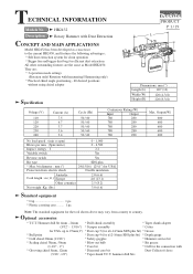
...to country. Hammer drill bit 4mm - 24mm * Drill chuck assembly * Taper shank adapter (5/32" - 15/16") * Scraper assembly * Cotter for the tool shown above may vary from electric shock Double insulation Australia Cord length : m ( ft ) Europe 2.0 (6.6) 4.0 (13.1) Other countries 2.5 (8.2) Net ...grease (1-1/2", 2") * Core bit * Cuff for ø12-16mm SDS plus * Max. hammer drill bits HR2432 Description Rotary Hammer with Dust Extraction CONCEPT AND MAIN APPLICATIONS Model HR2432 has been developed as a successor to 25mm(1") * Dust cup 5 (for ø6-14.5mm SDS plus ...
...to country. Hammer drill bit 4mm - 24mm * Drill chuck assembly * Taper shank adapter (5/32" - 15/16") * Scraper assembly * Cotter for the tool shown above may vary from electric shock Double insulation Australia Cord length : m ( ft ) Europe 2.0 (6.6) 4.0 (13.1) Other countries 2.5 (8.2) Net ...grease (1-1/2", 2") * Core bit * Cuff for ø12-16mm SDS plus * Max. hammer drill bits HR2432 Description Rotary Hammer with Dust Extraction CONCEPT AND MAIN APPLICATIONS Model HR2432 has been developed as a successor to 25mm(1") * Dust cup 5 (for ø6-14.5mm SDS plus ...

Technical Reference
Page 2
... / 19 Repair CAUTION: Disconnect the machine and remove the drill bits from the machine for safety before repair/ maintenance ! [1] NECESSARY REPAIRING TOOLS Code No. 1R003 1R004 1R008 1R022 1R023 1R034 1R038 1R164 1R165 1R212 1R236 1R240 1R241 1R252 1R263 1R269 1R306 Descriptions Retaining Ring Pliers ST-2N ... degrees) Bearing Plate Pipe Ring for Arbor Press Bearing Setting Plate 12.2 Armature Holder 32 Set for Use with Vise Ring Spring Setting Tool A Ring Spring Setting Tool B Tips for Retaining Ring Pliers Round Bar for Arbor 7-100 Round Bar for Arbor 11-100 Round Bar for Arbor 12-100 Round...
... / 19 Repair CAUTION: Disconnect the machine and remove the drill bits from the machine for safety before repair/ maintenance ! [1] NECESSARY REPAIRING TOOLS Code No. 1R003 1R004 1R008 1R022 1R023 1R034 1R038 1R164 1R165 1R212 1R236 1R240 1R241 1R252 1R263 1R269 1R306 Descriptions Retaining Ring Pliers ST-2N ... degrees) Bearing Plate Pipe Ring for Arbor Press Bearing Setting Plate 12.2 Armature Holder 32 Set for Use with Vise Ring Spring Setting Tool A Ring Spring Setting Tool B Tips for Retaining Ring Pliers Round Bar for Arbor 7-100 Round Bar for Arbor 11-100 Round Bar for Arbor 12-100 Round...

Technical Reference
Page 3
... of cam Whole of teeth portion Gear housing complete Fig. 1 Cap 35 (Oil seal) Needle bearing complete Steel ball 7.0 Spur gear 51 Tool holder Piston joint Piston cylinder Change lever O ring 17 Lock plate complete O ring 68 Inner housing complete Helical gear 5 Armature Spur gear 10... Cam shaft Clutch cam Swash bearing 10 Helical gear 26 P 3 / 19 Repair [2] LUBRICATION Apply the following Makita grease to protect parts and product from unusual abrasion. * Grease RA No.1 (Brown) to the portions marked with black triangle * Grease FA No.2...
... of cam Whole of teeth portion Gear housing complete Fig. 1 Cap 35 (Oil seal) Needle bearing complete Steel ball 7.0 Spur gear 51 Tool holder Piston joint Piston cylinder Change lever O ring 17 Lock plate complete O ring 68 Inner housing complete Helical gear 5 Armature Spur gear 10... Cam shaft Clutch cam Swash bearing 10 Helical gear 26 P 3 / 19 Repair [2] LUBRICATION Apply the following Makita grease to protect parts and product from unusual abrasion. * Grease RA No.1 (Brown) to the portions marked with black triangle * Grease FA No.2...

Technical Reference
Page 4
...washer with ring spring 19. 4. And then, secure them with steel ball 7.0. 3. Apply grease to steel ball 7.0 and cap 35 referring to tool holder. Assemble ring 21 and chuck cover to [2] LUBRICATION in page 3. 2. B. The notch portion of ring spring 19 should face the opposite ... portion of ring spring 19 < Wrong > Fig. 2 Cap 35 Ring spring 19 Chuck cover Steel ball 7.0 Guide washer Conical compression spring 21-2 Tool holder Ring 21 Chuck cover [3] -2. Assembling Chuck Section 1. Slide down chuck cover in the direction of gear housing, and attach cap 35. <...
...washer with ring spring 19. 4. And then, secure them with steel ball 7.0. 3. Apply grease to steel ball 7.0 and cap 35 referring to tool holder. Assemble ring 21 and chuck cover to [2] LUBRICATION in page 3. 2. B. The notch portion of ring spring 19 should face the opposite ... portion of ring spring 19 < Wrong > Fig. 2 Cap 35 Ring spring 19 Chuck cover Steel ball 7.0 Guide washer Conical compression spring 21-2 Tool holder Ring 21 Chuck cover [3] -2. Assembling Chuck Section 1. Slide down chuck cover in the direction of gear housing, and attach cap 35. <...

Technical Reference
Page 8
...section from inner housing complete as illustrated in the illustrations. See Fig. 22. Assembling Fan Housing See Fig. 18. Separate gear housing from tool holder. Remove ring spring 28 with gray color in Fig. 19. 4. When mounting fan housing A to fan housing B, apply adhesive (... 28 Compression spring 31 Spur gear 51 Round bars for arbor Retaining ring pliers Washer 30 Retaining ring pliers Spur gear 51 Washer 30 Tool holder Disassemble change lever from gear housing as illustrated in [3] -3. Disassemble washer 30, compression spring 31 and spur gear 51 from motor...
...section from inner housing complete as illustrated in the illustrations. See Fig. 22. Assembling Fan Housing See Fig. 18. Separate gear housing from tool holder. Remove ring spring 28 with gray color in Fig. 19. 4. When mounting fan housing A to fan housing B, apply adhesive (... 28 Compression spring 31 Spur gear 51 Round bars for arbor Retaining ring pliers Washer 30 Retaining ring pliers Spur gear 51 Washer 30 Tool holder Disassemble change lever from gear housing as illustrated in [3] -3. Disassemble washer 30, compression spring 31 and spur gear 51 from motor...

Technical Reference
Page 9
...ring spring 28 to the outside of the hole. See Fig.23. Refer to [3] -8. Mount flat washer 28. Refer to tool holder. Disassembling Impact Bolt 1. Disassembling Tool Holder Section , remove ring spring 28, washer 30, compression spring 31 and spur gear 51 from the inner groove as illustrated in.... Refer to the direction of swash bearing section into inner housing. Cap 35 side 3. Hold tool holder with arbor press, mount ring spring 28. No.1R038 Armature holder Inner groove of tool holder O ring case Cap 35 side Inner housing side Vise Ring spring 28 off from the ...
...ring spring 28 to the outside of the hole. See Fig.23. Refer to [3] -8. Mount flat washer 28. Refer to tool holder. Disassembling Impact Bolt 1. Disassembling Tool Holder Section , remove ring spring 28, washer 30, compression spring 31 and spur gear 51 from the inner groove as illustrated in.... Refer to the direction of swash bearing section into inner housing. Cap 35 side 3. Hold tool holder with arbor press, mount ring spring 28. No.1R038 Armature holder Inner groove of tool holder O ring case Cap 35 side Inner housing side Vise Ring spring 28 off from the ...

Technical Reference
Page 10
...'s hole. See Fig.27. * O ring case equipped with O ring 9 * O ring 15 * Ring 9 * Impact bolt equipped with O ring 9 into tool holder. Refer to [2] LUBRICATION. * O ring 9 for O ring case * O ring 15 * O ring 12 for arbor" and push ring spring 28 as deep as illustrated in Fig. ...26. 6. Ring spring 28 has to the inner groove of tool holder neatly. Insert "No.1R236 Round bar for impact bolt 2. P 10 / 19 Repair [3] -10. Insert impact bolt with O ring 12, ring 9, O ring 15 and O ring...
...'s hole. See Fig.27. * O ring case equipped with O ring 9 * O ring 15 * Ring 9 * Impact bolt equipped with O ring 9 into tool holder. Refer to [2] LUBRICATION. * O ring 9 for O ring case * O ring 15 * O ring 12 for arbor" and push ring spring 28 as deep as illustrated in Fig. ...26. 6. Ring spring 28 has to the inner groove of tool holder neatly. Insert "No.1R236 Round bar for impact bolt 2. P 10 / 19 Repair [3] -10. Insert impact bolt with O ring 12, ring 9, O ring 15 and O ring...

Technical Reference
Page 11
.... Finally swash bearing section and change plate is fastened with pulling it out. Repair P 11 / 19 [3] -12. Fig. 30 Hex socket head bolts M4x12 4. Remove tool holder section and swash bearing section. Disassemble stop ring E-4, flat washer 5 and compression spring 6 with pulling off these hex socket head bolts M4x12 for disassembling...
.... Finally swash bearing section and change plate is fastened with pulling it out. Repair P 11 / 19 [3] -12. Fig. 30 Hex socket head bolts M4x12 4. Remove tool holder section and swash bearing section. Disassemble stop ring E-4, flat washer 5 and compression spring 6 with pulling off these hex socket head bolts M4x12 for disassembling...
