
Owners Manual
Page 2
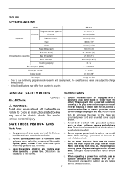
... invite accidents. 2. GENERAL SAFETY RULES Electrical Safety (For All Tools) USA002-2 WARNING: Read and understand all instructions listed below, may ignite the dust or fumes. 3. tion eliminates the need for outdoor use an outdoor extension cord marked "W-A" or "W". liquids, gases, or dust. Keep bystanders, children, and visitors away while operating a power tool. drilling depth 100 mm (4") (Adjusting depth) 0 - 100 mm (4") Dust extraction capacities Max. Water entering a power tool will fit in...
... invite accidents. 2. GENERAL SAFETY RULES Electrical Safety (For All Tools) USA002-2 WARNING: Read and understand all instructions listed below, may ignite the dust or fumes. 3. tion eliminates the need for outdoor use an outdoor extension cord marked "W-A" or "W". liquids, gases, or dust. Keep bystanders, children, and visitors away while operating a power tool. drilling depth 100 mm (4") (Adjusting depth) 0 - 100 mm (4") Dust extraction capacities Max. Water entering a power tool will fit in...
Owners Manual
Page 3
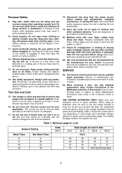
... hair can be repaired. 18. Use safety equipment. Use clamps or other untrained persons. Holding the work by poorly maintained tools. 22. Tools are caused by hand or against your hair, clothing, and gloves away from the power source before plugging in personal injury. 13. Use of cord in moving parts. Table 1 shows the correct size to follow Maintenance instructions may result in . A wrench or a key that cannot be...
... hair can be repaired. 18. Use safety equipment. Use clamps or other untrained persons. Holding the work by poorly maintained tools. 22. Tools are caused by hand or against your hair, clothing, and gloves away from the power source before plugging in personal injury. 13. Use of cord in moving parts. Table 1 shows the correct size to follow Maintenance instructions may result in . A wrench or a key that cannot be...
Owners Manual
Page 4
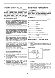
... number of the tool "live " wire will loosen up for tool. Check tightness of operator comfort during extended use ) replace strict adherence to the bit immediately after operation; Always be sure that the tool is difficult. 7. SAVE THESE INSTRUCTIONS WARNING: MISUSE or failure to produce vibration. Switch trigger 2. Wear a hard hat (safety helmet), safety glasses and/or face shield. Under normal operation, the tool is below when using...
... number of the tool "live " wire will loosen up for tool. Check tightness of operator comfort during extended use ) replace strict adherence to the bit immediately after operation; Always be sure that the tool is difficult. 7. SAVE THESE INSTRUCTIONS WARNING: MISUSE or failure to produce vibration. Switch trigger 2. Wear a hard hat (safety helmet), safety glasses and/or face shield. Under normal operation, the tool is below when using...

Owners Manual
Page 5
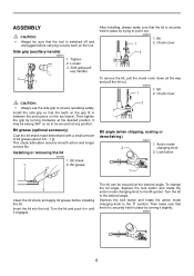
.... Tool speed is increased by increasing pressure on the mode change the direction of the tool. • Hole saws cannot be sure that the action mode changing knob is reached. Lock button 3. Release the switch trigger to actuate too frequently. 5 To start the tool, simply pull the switch trigger. Reversing switch lever 1 B 2 This tool has a reversing switch to a complete stop . For continuous operation, pull the switch trigger and then push in one of rotation before operation. • Use...
.... Tool speed is increased by increasing pressure on the mode change the direction of the tool. • Hole saws cannot be sure that the action mode changing knob is reached. Lock button 3. Release the switch trigger to actuate too frequently. 5 To start the tool, simply pull the switch trigger. Reversing switch lever 1 B 2 This tool has a reversing switch to a complete stop . For continuous operation, pull the switch trigger and then push in one of rotation before operation. • Use...
Owners Manual
Page 6
... mode changing knob to the desired angle. Chuck cover CAUTION: • Always use the side grip to the O symbol. Bit grease (optional accessory) Coat the bit shank head beforehand with a small amount of bit grease (about 0.5 - 1 g). Insert the bit into the tool. The bit can be secured at the desired position. To change the bit angle, depress the lock button and rotate the action mode changing knob to ensure operating safety. iary handle) 3 2 1 After installing...
... mode changing knob to the desired angle. Chuck cover CAUTION: • Always use the side grip to the O symbol. Bit grease (optional accessory) Coat the bit shank head beforehand with a small amount of bit grease (about 0.5 - 1 g). Insert the bit into the tool. The bit can be secured at the desired position. To change the bit angle, depress the lock button and rotate the action mode changing knob to ensure operating safety. iary handle) 3 2 1 After installing...

Owners Manual
Page 7
Depth gauge (optional accessory) 005879 1. Dust cup (optional accessory) 005891 1. And then tighten the clamp screw clockwise to the bit as follows. 003187 Bit diameter Dust cup 5 6 mm (1/4") - 14.5 mm (9/16") Dust cup 9 12 mm (15/32") - 16 mm (5/8") 1 2 Keeping the angle of the dust bag with the tool, the dust extractor attachment cannot be installed on the tool because of the port to be used only for drilling holes of...
Depth gauge (optional accessory) 005879 1. Dust cup (optional accessory) 005891 1. And then tighten the clamp screw clockwise to the bit as follows. 003187 Bit diameter Dust cup 5 6 mm (1/4") - 14.5 mm (9/16") Dust cup 9 12 mm (15/32") - 16 mm (5/8") 1 2 Keeping the angle of the dust bag with the tool, the dust extractor attachment cannot be installed on the tool because of the port to be used only for drilling holes of...

Owners Manual
Page 8
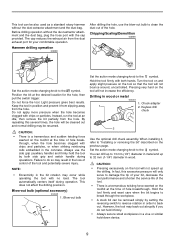
... the gauge, and then tighten the screw by turning it clockwise. Drilling without dust extractor attachment 005888 1. Fastener 1 Tighten the clamp screw by turning it clockwise to time. Pull the fastener out of dust extracting power. Dust exhaust 3 8 Clamping screw 1 In drilling operation, hold the tool so that the stopper could slide on the depth gauge of dust extracting power. Depth adjustment 005885 1. Clamping screw OPERATION Drilling with the sur- Complete con- 1 tact with dust extractor attachment 005886 1. Remove the dust bag...
... the gauge, and then tighten the screw by turning it clockwise. Drilling without dust extractor attachment 005888 1. Fastener 1 Tighten the clamp screw by turning it clockwise to time. Pull the fastener out of dust extracting power. Dust exhaust 3 8 Clamping screw 1 In drilling operation, hold the tool so that the stopper could slide on the depth gauge of dust extracting power. Depth adjustment 005885 1. Clamping screw OPERATION Drilling with the sur- Complete con- 1 tact with dust extractor attachment 005886 1. Remove the dust bag...
Owners Manual
Page 9
... do so may result in the bit rotation may be removed simply by both hands. Position the bit at the time of your comfortable operation. Do not apply more pressure when the hole becomes clogged with both side grip and switch handle during operation. Chuck adapter 1 2. Set the action mode changing knob to "Installing or removing the bit" described on the tool will only serve to clean the...
... do so may result in the bit rotation may be removed simply by both hands. Position the bit at the time of your comfortable operation. Do not apply more pressure when the hole becomes clogged with both side grip and switch handle during operation. Chuck adapter 1 2. Set the action mode changing knob to "Installing or removing the bit" described on the tool will only serve to clean the...
Owners Manual
Page 10
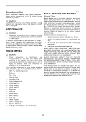
... Factory Service Centers, always using "rotation with your local Makita service center. • SDS-Plus Carbide-tipped bits • Bull point • Cold chisel • Scaling chisel • Grooving chisel • Drill chuck assembly • Drill chuck S13 • Chuck adapter • Chuck key S13 • Bit grease • Side grip • Depth gauge • Blow-out bulb • Dust cup • Safety goggles • Plastic carrying case • Keyless drill chuck •...
... Factory Service Centers, always using "rotation with your local Makita service center. • SDS-Plus Carbide-tipped bits • Bull point • Cold chisel • Scaling chisel • Grooving chisel • Drill chuck assembly • Drill chuck S13 • Chuck adapter • Chuck key S13 • Bit grease • Side grip • Depth gauge • Blow-out bulb • Dust cup • Safety goggles • Plastic carrying case • Keyless drill chuck •...
Parts Breakdown
Page 2
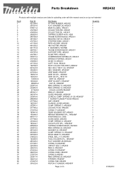
... Page 2 of 4 Quantity 1 1 1 1 1 1 1 1 1 1 1 1 1 1 1 1 1 1 1 1 1 1 1 1 1 1 1 1 1 1 1 1 1 1 4 1 1 1 1 1 1 1 2 1 2 1 2 1 1 1 1 1 1 1 1 1 1 1 1 1 1 1 1 1 8/18/2010 BOLT M8 X 120, HP2050F HEX. SCREW FLANGE PT4X45 HR2410 CAP, HR2455 CHANGE LEVER,HR2455 COMP. SPRING 3, HR2450F LOCK BUTTON, HR2455 O RING 17,HR2450F GEAR HOUSING SET,HR2455 NEEDLE BEARING CPL., HR2450F STOP RING E-3, 4304 GUIDE BASE, HR2455 COMP. SPRING 21-29, HR2450F T. Parts Breakdown HR2432 Products with multiple versions are listed in subsiding order with the newest version on top not...
... Page 2 of 4 Quantity 1 1 1 1 1 1 1 1 1 1 1 1 1 1 1 1 1 1 1 1 1 1 1 1 1 1 1 1 1 1 1 1 1 1 4 1 1 1 1 1 1 1 2 1 2 1 2 1 1 1 1 1 1 1 1 1 1 1 1 1 1 1 1 1 8/18/2010 BOLT M8 X 120, HP2050F HEX. SCREW FLANGE PT4X45 HR2410 CAP, HR2455 CHANGE LEVER,HR2455 COMP. SPRING 3, HR2450F LOCK BUTTON, HR2455 O RING 17,HR2450F GEAR HOUSING SET,HR2455 NEEDLE BEARING CPL., HR2450F STOP RING E-3, 4304 GUIDE BASE, HR2455 COMP. SPRING 21-29, HR2450F T. Parts Breakdown HR2432 Products with multiple versions are listed in subsiding order with the newest version on top not...
Parts Breakdown
Page 3
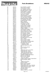
...-2 MOTOR HOUSING, HR2432 1 111 417632-0 N/A 1 112 861193-6 NAME PLATE, HR2432 1 113 689111-0 SPACER, HP2050F 2 114 643988-7 BRUSH HOLDER, HP2050F 1 115 819063-3 MAKITA LABEL, DA3010F 1 116 191927-6 CARBON BRUSH SET CB-407, BO5030K 1 116 195007-0 CARBON BRUSH SET CB-407, FS4200 1 117 643989-5 BRUSH HOLDER,HP2050F 1 118 803356-8 S/N LABEL, HR2432 1 119 650508-0 SWITCH, HR2450F 1 120 153284-0 HANDLE COVER CPL., HP2050F 1 Page 3 of 4 8/18/2010 SPRING 7, HR2450F 1 68 226399-7 SPUR GEAR 10...
...-2 MOTOR HOUSING, HR2432 1 111 417632-0 N/A 1 112 861193-6 NAME PLATE, HR2432 1 113 689111-0 SPACER, HP2050F 2 114 643988-7 BRUSH HOLDER, HP2050F 1 115 819063-3 MAKITA LABEL, DA3010F 1 116 191927-6 CARBON BRUSH SET CB-407, BO5030K 1 116 195007-0 CARBON BRUSH SET CB-407, FS4200 1 117 643989-5 BRUSH HOLDER,HP2050F 1 118 803356-8 S/N LABEL, HR2432 1 119 650508-0 SWITCH, HR2450F 1 120 153284-0 HANDLE COVER CPL., HP2050F 1 Page 3 of 4 8/18/2010 SPRING 7, HR2450F 1 68 226399-7 SPUR GEAR 10...

Flyer (English)
Page 1
... 3x more efficient POWER Large aluminum fan for powerful dust collection and lightweight design (only 6.6 lbs.) for continuous operation DURABILITY Adjustable dust bag and elbow-shaped dust nozzle is secured and aligned close to the tool for longer life and increased dust efficiency ACCURACY Hammering with Rotation Rotation Only Chisel Angle Setting Hammer Only Model HR2432 3-mode switch for "rotation only," "hammering with 40 different locking positions DUST COLLECTION
... 3x more efficient POWER Large aluminum fan for powerful dust collection and lightweight design (only 6.6 lbs.) for continuous operation DURABILITY Adjustable dust bag and elbow-shaped dust nozzle is secured and aligned close to the tool for longer life and increased dust efficiency ACCURACY Hammering with Rotation Rotation Only Chisel Angle Setting Hammer Only Model HR2432 3-mode switch for "rotation only," "hammering with 40 different locking positions DUST COLLECTION

Flyer (English)
Page 2
... I 3-mode operation; All models and accessories subject to change without prior notice. I Specially designed carbide tip geometry for increased penetration I Core body length: 4-1/4" I Usable drilling depth: 3-1/4" I From 1" to 1" diameter I One touch sliding chuck for easy bit changes; 1" ROTARY HAMMER with reduced operator fatigue Standard Equipment I Dust Bag Assembly (122708-7) I Side Handle (152521-9) I Bit Grease (181573-3) I Dust Cap (421727-3) I Tool Case (824729-2) Specifications Capacities: Concrete Steel Wood No Load Speed Blows per Minute AMPS (120V...
... I 3-mode operation; All models and accessories subject to change without prior notice. I Specially designed carbide tip geometry for increased penetration I Core body length: 4-1/4" I Usable drilling depth: 3-1/4" I From 1" to 1" diameter I One touch sliding chuck for easy bit changes; 1" ROTARY HAMMER with reduced operator fatigue Standard Equipment I Dust Bag Assembly (122708-7) I Side Handle (152521-9) I Bit Grease (181573-3) I Dust Cap (421727-3) I Tool Case (824729-2) Specifications Capacities: Concrete Steel Wood No Load Speed Blows per Minute AMPS (120V...
Technical Reference
Page 1
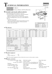
...point * Dust cup 9 (for ø12-16mm SDS plus * Max. hammer drill bits Optional accessories * T.C.T. TECHNICAL INFORMATION Models No. HR2432 Description Rotary Hammer with Dust Extraction CONCEPT AND MAIN APPLICATIONS Model HR2432 has been developed as Model HR2450. Hammer drill bit 4mm - 24mm * Drill chuck assembly * Taper shank adapter (5/32" - 15/16") * Scraper assembly * Cotter for the connection with hammering/ Hammering only) * Practical chisel angle positioning - 40 desired positions without using chisel adapter Specification PRODUCT P 1 / 19 L W H Dimensions: mm...
...point * Dust cup 9 (for ø12-16mm SDS plus * Max. hammer drill bits Optional accessories * T.C.T. TECHNICAL INFORMATION Models No. HR2432 Description Rotary Hammer with Dust Extraction CONCEPT AND MAIN APPLICATIONS Model HR2432 has been developed as Model HR2450. Hammer drill bit 4mm - 24mm * Drill chuck assembly * Taper shank adapter (5/32" - 15/16") * Scraper assembly * Cotter for the connection with hammering/ Hammering only) * Practical chisel angle positioning - 40 desired positions without using chisel adapter Specification PRODUCT P 1 / 19 L W H Dimensions: mm...

Technical Reference
Page 3
... joint is assembled Pin portion Whole part Inner portion where tool holder contacts The groove where O ring 68 is assembled Spiral portion The hole where cam shaft contacts Convex portion of cam Whole of teeth portion Gear housing complete Fig. 1 Cap 35 (Oil seal) Needle bearing complete Steel ball 7.0 Spur gear 51 Tool holder Piston joint Piston cylinder Change lever O ring 17 Lock plate complete...
... joint is assembled Pin portion Whole part Inner portion where tool holder contacts The groove where O ring 68 is assembled Spiral portion The hole where cam shaft contacts Convex portion of cam Whole of teeth portion Gear housing complete Fig. 1 Cap 35 (Oil seal) Needle bearing complete Steel ball 7.0 Spur gear 51 Tool holder Piston joint Piston cylinder Change lever O ring 17 Lock plate complete...
Technical Reference
Page 6
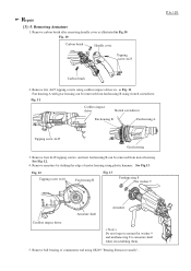
... Cordless impact driver < Note > Do not forget to mount flat washer 9 and urethane ring 8 to armature shaft when reassembling them. 5. Remove ball bearing of motor housing using slotted screwdriver. See Fig.13. Removing Armature 1. Fig. 10 Carbon brush Handle cover Tapping screw 4x25 P 6 / 19 Carbon brush 2. See Fig. 12. 4. Fan housing A with gear housing can be removed from motor housing. Remove armature by striking the edge of commutator end using cordless impact driver etc. Remove carbon brush after removing handle...
... Cordless impact driver < Note > Do not forget to mount flat washer 9 and urethane ring 8 to armature shaft when reassembling them. 5. Remove ball bearing of motor housing using slotted screwdriver. See Fig.13. Removing Armature 1. Fig. 10 Carbon brush Handle cover Tapping screw 4x25 P 6 / 19 Carbon brush 2. See Fig. 12. 4. Fan housing A with gear housing can be removed from motor housing. Remove armature by striking the edge of commutator end using cordless impact driver etc. Remove carbon brush after removing handle...

Technical Reference
Page 7
Repair P 7 / 19 [3] -6. Fig. 15 Fig. 16 Fig. 17 1R269 Bearing Extractor (small) Retaining ring S-15 Ram of arbor press Helical gear 5 Dust guard Flat washer 9 Ball bearing 609 LLU 1R008 Tips for retaining ring pliers as Fig.16. 5. Remove fan housing A from helical gear 5 with arbor press. Remove dust guard and fan 81 at a time using 1R008 Tips for retaining ring pliers Table of fan...
Repair P 7 / 19 [3] -6. Fig. 15 Fig. 16 Fig. 17 1R269 Bearing Extractor (small) Retaining ring S-15 Ram of arbor press Helical gear 5 Dust guard Flat washer 9 Ball bearing 609 LLU 1R008 Tips for retaining ring pliers as Fig.16. 5. Remove fan housing A from helical gear 5 with arbor press. Remove dust guard and fan 81 at a time using 1R008 Tips for retaining ring pliers Table of fan...
Technical Reference
Page 15
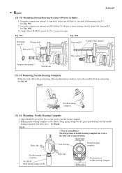
P 15 / 19 Repair [3] -14. Assemble compression spring 6 and flat washer 5 to the pin of needle baring complete. 2. See Fig. 39H. 10. Fig. 39G Fig. 39H Retaining ring S-7 Change plate Compression spring 6 Stop ring E-5 Spur gear 10 Flat washer 5 Compression spring 7 Clutch cam [3] -15. Then needle bearing complete can be disassembled from gear housing. Apply MAKITA grease RA No.1 to cam shaft with arbor press. See Fig...
P 15 / 19 Repair [3] -14. Assemble compression spring 6 and flat washer 5 to the pin of needle baring complete. 2. See Fig. 39H. 10. Fig. 39G Fig. 39H Retaining ring S-7 Change plate Compression spring 6 Stop ring E-5 Spur gear 10 Flat washer 5 Compression spring 7 Clutch cam [3] -15. Then needle bearing complete can be disassembled from gear housing. Apply MAKITA grease RA No.1 to cam shaft with arbor press. See Fig...

Technical Reference
Page 16
.... 43. can be replaced. Strain relief [4] Maintenance It is recommended to change the following parts, when replacing carbon brushes. Repair [3] -17. Brush holder Cord guard Power supply cord Tapping screw 4x18: 2 pcs. Fig. 43 Steel ball 7.0 O ring 12 O ring 15 O ring 9 O ring 16 Switch, noise suppressor, power supply cord, etc. See Fig.42. Fig. 42 P 16 / 19 Brush holder Noise suppressor Switch Handle cover Tapping s crew 4 x 25: 3 pcs. Replacing Electrical Parts in Handle Remove handle cover by unscrewing...
.... 43. can be replaced. Strain relief [4] Maintenance It is recommended to change the following parts, when replacing carbon brushes. Repair [3] -17. Brush holder Cord guard Power supply cord Tapping screw 4x18: 2 pcs. Fig. 43 Steel ball 7.0 O ring 12 O ring 15 O ring 9 O ring 16 Switch, noise suppressor, power supply cord, etc. See Fig.42. Fig. 42 P 16 / 19 Brush holder Noise suppressor Switch Handle cover Tapping s crew 4 x 25: 3 pcs. Replacing Electrical Parts in Handle Remove handle cover by unscrewing...

Technical Reference
Page 17
... Blue or White Switch Line filter Power supply cord Noise suppressor Color index of lead wires' sheath Black White Clear Red Blue Brown For other countries Brush holder Field Grounding terminal Brush holder Brown or Black Blue or White Switch Power supply cord Noise suppressor (with three lead wires) Noise suppressor with two lead wires is not used for this model.) Thus, the specifications may vary...
... Blue or White Switch Line filter Power supply cord Noise suppressor Color index of lead wires' sheath Black White Clear Red Blue Brown For other countries Brush holder Field Grounding terminal Brush holder Brown or Black Blue or White Switch Power supply cord Noise suppressor (with three lead wires) Noise suppressor with two lead wires is not used for this model.) Thus, the specifications may vary...


