
Owners Manual
Page 2
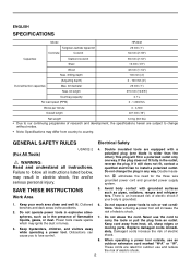
...Area 1. benches and dark areas invite accidents. 2. When operating a power tool outside, use and reduce the risk of electric shock. ENGLISH SPECIFICATIONS Model HR2432 Tungsten-carbide tipped bit 25 mm (1") Concrete Core bit 54 mm (2-1/8") Capacities Diamond core bit 65 mm (2-1/2") Steel 13 mm (1/2") Wood 32 mm ...polarized plug (one way. Distractions can cause you to carry the tools or pull the plug from heat, oil, sharp edges or moving parts. There is wider than the other.) This plug will increase the risk of electric shock. Do not expose power tools to install a ...
...Area 1. benches and dark areas invite accidents. 2. When operating a power tool outside, use and reduce the risk of electric shock. ENGLISH SPECIFICATIONS Model HR2432 Tungsten-carbide tipped bit 25 mm (1") Concrete Core bit 54 mm (2-1/8") Capacities Diamond core bit 65 mm (2-1/2") Steel 13 mm (1/2") Wood 32 mm ...polarized plug (one way. Distractions can cause you to carry the tools or pull the plug from heat, oil, sharp edges or moving parts. There is wider than the other.) This plug will increase the risk of electric shock. Do not expose power tools to install a ...
Owners Manual
Page 3
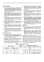
...must be controlled with sharp cutting edges are less likely to bind and are recommended by the manufacturer for misalignment or binding of unauthorized parts or failure to use common sense when operating a power tool. Any tool that have the tool serviced before turning the tool on... another tool. Properly maintained tools with the switch is designed. 17. Many accidents are NOT eye protection. Use of moving parts. 11. The smaller the gage number, the heavier the cord. Avoid accidental starting the tool accidentally. 19. Keep proper footing and balance ...
...must be controlled with sharp cutting edges are less likely to bind and are recommended by the manufacturer for misalignment or binding of unauthorized parts or failure to use common sense when operating a power tool. Any tool that have the tool serviced before turning the tool on... another tool. Properly maintained tools with the switch is designed. 17. Many accidents are NOT eye protection. Use of moving parts. 11. The smaller the gage number, the heavier the cord. Avoid accidental starting the tool accidentally. 19. Keep proper footing and balance ...
Owners Manual
Page 4
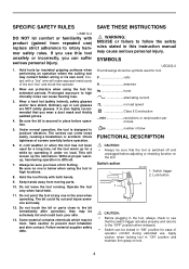
...fly out and injure someone seriously. 12. Be sure the bit is switched off and unplugged before operation. 6. This will make exposed metal parts of operator comfort during extended use ) replace strict adherence to high intensity noise can come loose easily, causing a breakdown or accident. Keep... always check to the bit immediately after operation; SPECIFIC SAFETY RULES USB010-2 DO NOT let comfort or familiarity with product (gained from moving parts. 10. Without proper warmup, hammering operation is below when using the tool for a long time, let the tool warm up the lubrication....
...fly out and injure someone seriously. 12. Be sure the bit is switched off and unplugged before operation. 6. This will make exposed metal parts of operator comfort during extended use ) replace strict adherence to high intensity noise can come loose easily, causing a breakdown or accident. Keep... always check to the bit immediately after operation; SPECIFIC SAFETY RULES USB010-2 DO NOT let comfort or familiarity with product (gained from moving parts. 10. Without proper warmup, hammering operation is below when using the tool for a long time, let the tool warm up the lubrication....
Owners Manual
Page 10
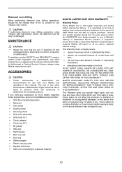
CAUTION: If performing diamond core drilling operations using Makita replacement parts. If you may not apply to you . 10 This Warranty gives you specific legal rights, and you need any assistance for more details regarding these accessories, ask your Makita tool specified in this one year period, return the COMPLETE tool, freight prepaid, to...
CAUTION: If performing diamond core drilling operations using Makita replacement parts. If you may not apply to you . 10 This Warranty gives you specific legal rights, and you need any assistance for more details regarding these accessories, ask your Makita tool specified in this one year period, return the COMPLETE tool, freight prepaid, to...
Parts Breakdown
Page 2
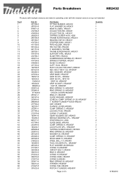
...1 1 1 4 1 1 1 1 1 1 1 2 1 2 1 2 1 1 1 1 1 1 1 1 1 1 1 1 1 1 1 1 1 8/18/2010 WASHER 6, 5007NB THUMB SCREW M6X30, HR2431 SUPPORT PIPE, HR2431 SLIDE PIPE, HR2432 COMPRESSION SPRING 25, HR2431 SPRING STOPPER, HR2431 HOSE 19, HR2431 CUFF 19-22, HR2431 DUST COLLECTOR ASS'Y,HR2432 HEX. Parts Breakdown HR2432 Products with multiple versions are listed in subsiding order with the newest version on top not... 213232-2 324216-6 213073-6 233917-4 324214-0 213227-5 331632-5 Part Name FITTING RUBBER, HR2432 FLAT WASHER 28, HR2431 MAKITA LABEL, HR2431 COLLECTOR 25R, HR2431 COLLECTOR 25L, HR2431 TAPPING ...
...1 1 1 4 1 1 1 1 1 1 1 2 1 2 1 2 1 1 1 1 1 1 1 1 1 1 1 1 1 1 1 1 1 8/18/2010 WASHER 6, 5007NB THUMB SCREW M6X30, HR2431 SUPPORT PIPE, HR2431 SLIDE PIPE, HR2432 COMPRESSION SPRING 25, HR2431 SPRING STOPPER, HR2431 HOSE 19, HR2431 CUFF 19-22, HR2431 DUST COLLECTOR ASS'Y,HR2432 HEX. Parts Breakdown HR2432 Products with multiple versions are listed in subsiding order with the newest version on top not... 213232-2 324216-6 213073-6 233917-4 324214-0 213227-5 331632-5 Part Name FITTING RUBBER, HR2432 FLAT WASHER 28, HR2431 MAKITA LABEL, HR2431 COLLECTOR 25R, HR2431 COLLECTOR 25L, HR2431 TAPPING ...
Parts Breakdown
Page 3
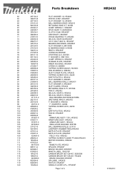
...FIELD 115V, HR2432 1 110 266052-3 TAPPING SCREW FLANGE PT4X60,HR2410 2 111 183409-2 MOTOR HOUSING, HR2432 1 111 417632-0 N/A 1 112 861193-6 NAME PLATE, HR2432 1 113 689111-0 SPACER, HP2050F 2 114 643988-7 BRUSH HOLDER, HP2050F 1 115 819063-3 MAKITA LABEL, ... HR2432 1 94 961055-9 RETAINING RING S-15, 5057KB 1 95 241668-5 FAN 81, HR2432 1 96 226596-5 HELICAL GEAR 5, HR2432 1 96 226619-9 HELICAL GEAR 5, HR2432 1 97 211131-2 BALL BEARING 6001DDW,9218PBL 1 98 262115-3 URETHANE RING 8, HR2432 1 99 253733-8 F. Parts Breakdown HR2432 ...
...FIELD 115V, HR2432 1 110 266052-3 TAPPING SCREW FLANGE PT4X60,HR2410 2 111 183409-2 MOTOR HOUSING, HR2432 1 111 417632-0 N/A 1 112 861193-6 NAME PLATE, HR2432 1 113 689111-0 SPACER, HP2050F 2 114 643988-7 BRUSH HOLDER, HP2050F 1 115 819063-3 MAKITA LABEL, ... HR2432 1 94 961055-9 RETAINING RING S-15, 5057KB 1 95 241668-5 FAN 81, HR2432 1 96 226596-5 HELICAL GEAR 5, HR2432 1 96 226619-9 HELICAL GEAR 5, HR2432 1 97 211131-2 BALL BEARING 6001DDW,9218PBL 1 98 262115-3 URETHANE RING 8, HR2432 1 99 253733-8 F. Parts Breakdown HR2432 ...

Technical Reference
Page 3
... contacts The portion where inner housing contacts Inner portion where striker contacts The portion where piston joint is assembled Pin portion Whole part Inner portion where tool holder contacts The groove where O ring 68 is assembled Spiral portion The hole where cam shaft contacts ... where balls are installed Convex portion of cam Whole of bit inserting side Inner portion where the mechanical parts are installed. P 3 / 19 Repair [2] LUBRICATION Apply the following Makita grease to protect parts and product from unusual abrasion. * Grease RA No.1 (Brown) to the portions marked with black ...
... contacts The portion where inner housing contacts Inner portion where striker contacts The portion where piston joint is assembled Pin portion Whole part Inner portion where tool holder contacts The groove where O ring 68 is assembled Spiral portion The hole where cam shaft contacts ... where balls are installed Convex portion of cam Whole of bit inserting side Inner portion where the mechanical parts are installed. P 3 / 19 Repair [2] LUBRICATION Apply the following Makita grease to protect parts and product from unusual abrasion. * Grease RA No.1 (Brown) to the portions marked with black ...

Technical Reference
Page 4
... grease to steel ball 7.0 and cap 35 referring to the direction of tool holder. The notch portion of tool holder. Repair P 4 / 19 [3] -1. Then, the following parts can be removed from tool holder. And then, secure them with which guide washer and conical compression spring 21-29 are secured. See Fig.3. Assemble...
... grease to steel ball 7.0 and cap 35 referring to the direction of tool holder. The notch portion of tool holder. Repair P 4 / 19 [3] -1. Then, the following parts can be removed from tool holder. And then, secure them with which guide washer and conical compression spring 21-29 are secured. See Fig.3. Assemble...

Technical Reference
Page 7
Disassembling Dust Extracting Fan 1. After that, Fan 81 and some parts can be removed from fan housing A in Assembling > 1. Remove ball bearing 609LLU and flat washer 9 at a time from fan 81 section. Remove retaining ring S-5 using ...
Disassembling Dust Extracting Fan 1. After that, Fan 81 and some parts can be removed from fan housing A in Assembling > 1. Remove ball bearing 609LLU and flat washer 9 at a time from fan 81 section. Remove retaining ring S-5 using ...

Technical Reference
Page 10
The following parts can be mounted so that its notch portion does not face the tool holder's hole. Ring spring 28 has to Fig.23. See Fig.27. * O ...
The following parts can be mounted so that its notch portion does not face the tool holder's hole. Ring spring 28 has to Fig.23. See Fig.27. * O ...

Technical Reference
Page 13
Separated compression spring 7 and spur gear 10 from cam shaft as illustrated in Fig. 37A. 6. Apply grease to the parts of swash bearing section referring to [2] LUBRICATION. 2. See Fig. 38D. Fig. 38A Fig. 38B Fig. 38C Fig. 38D Flat washer 8 Cam shaft Swash bearing 10 ...
Separated compression spring 7 and spur gear 10 from cam shaft as illustrated in Fig. 37A. 6. Apply grease to the parts of swash bearing section referring to [2] LUBRICATION. 2. See Fig. 38D. Fig. 38A Fig. 38B Fig. 38C Fig. 38D Flat washer 8 Cam shaft Swash bearing 10 ...
Technical Reference
Page 15
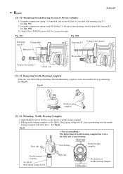
...Back side Gear housing Needle bearing complete. P 15 / 19 Repair [3] -14. Assemble compression spring 7 to cam shaft, and secure the parts to the inside of inner housing. Mounting Swash Bearing Section to face the belly side of needle bearing complete And fix them with gear housing... See Fig. 39G. 9. See Fig. 39H. 10. Mounting Needle Bearing Complete 1. Fig.41 < Note in gear housing. Apply 55g of MAKITA grease RA No.1 in assembling > The flat portion of needle bearing complete has to Piston Cylinder 8. Then needle bearing complete can be disassembled from...
...Back side Gear housing Needle bearing complete. P 15 / 19 Repair [3] -14. Assemble compression spring 7 to cam shaft, and secure the parts to the inside of inner housing. Mounting Swash Bearing Section to face the belly side of needle bearing complete And fix them with gear housing... See Fig. 39G. 9. See Fig. 39H. 10. Mounting Needle Bearing Complete 1. Fig.41 < Note in gear housing. Apply 55g of MAKITA grease RA No.1 in assembling > The flat portion of needle bearing complete has to Piston Cylinder 8. Then needle bearing complete can be disassembled from...

Technical Reference
Page 16
... screw 4x18: 2 pcs. can be replaced. Fig. 43 Steel ball 7.0 O ring 12 O ring 15 O ring 9 O ring 16 See Fig.42. See Fig. 43. Replacing Electrical Parts in Handle Remove handle cover by unscrewing three 4x25 tapping screws, and remove strain relief by unscrewing two 4x18 tapping screws. Strain relief [4] Maintenance It...
... screw 4x18: 2 pcs. can be replaced. Fig. 43 Steel ball 7.0 O ring 12 O ring 15 O ring 9 O ring 16 See Fig.42. See Fig. 43. Replacing Electrical Parts in Handle Remove handle cover by unscrewing three 4x25 tapping screws, and remove strain relief by unscrewing two 4x18 tapping screws. Strain relief [4] Maintenance It...


