
User Guide
Page 1
Preface Z97S SLI Krait Edition Motherboard G52-79221X4
Preface Z97S SLI Krait Edition Motherboard G52-79221X4

User Guide
Page 12
Preface ▍▍Contents Chapter 1 Getting Started 1-1 Packing Contents 1-2 Assembly Precautions 1-3 Motherboard Specifications 1-4 Connectors Quick Guide 1-7 Back Panel Quick Guide 1-9 CPU (Central Processing Unit 1-11 Introduction to the LGA 1150 CPU 1-11 CPU & Heatsink Installation 1-12 Memory 1-...
Preface ▍▍Contents Chapter 1 Getting Started 1-1 Packing Contents 1-2 Assembly Precautions 1-3 Motherboard Specifications 1-4 Connectors Quick Guide 1-7 Back Panel Quick Guide 1-9 CPU (Central Processing Unit 1-11 Introduction to the LGA 1150 CPU 1-11 CPU & Heatsink Installation 1-12 Memory 1-...

User Guide
Page 13
Preface Motherboard Installation 2-5 Power Connectors Installation 2-7 SATA HDD Installation 2-9 M.2 module Installation 2-10 Front Panel Connector Installation 2-11 JFP1 Connector Installation 2-11 Front Panel Audio Connector Installation 2-11 ...
Preface Motherboard Installation 2-5 Power Connectors Installation 2-7 SATA HDD Installation 2-9 M.2 module Installation 2-10 Front Panel Connector Installation 2-11 JFP1 Connector Installation 2-11 Front Panel Audio Connector Installation 2-11 ...
User Guide
Page 15
The Z97S SLI Krait Edition Series motherboards are based on Intel® Z97 Express chipset for choosing the Z97S SLI Krait Edition Series (MS-7922 v2.X) ATX motherboard. Designed to fit the advanced Intel® LGA1150 processor, the Z97S SLI Krait Edition Series motherboards deliver a high performance and professional desktop platform solution. Chapter 1 Getting Started Thank you for optimal system efficiency.
The Z97S SLI Krait Edition Series motherboards are based on Intel® Z97 Express chipset for choosing the Z97S SLI Krait Edition Series (MS-7922 v2.X) ATX motherboard. Designed to fit the advanced Intel® LGA1150 processor, the Z97S SLI Krait Edition Series motherboards deliver a high performance and professional desktop platform solution. Chapter 1 Getting Started Thank you for optimal system efficiency.

User Guide
Page 16
Packing Contents Motherboard Drivers & Utilities Disc Motherboard User Guide I/O Shield SATA Cable * These pictures are for reference only and may vary without notice. * The packing contents may vary according to the model you purchased. Chapter 1 Getting Started 1-2
Packing Contents Motherboard Drivers & Utilities Disc Motherboard User Guide I/O Shield SATA Cable * These pictures are for reference only and may vary without notice. * The packing contents may vary according to the model you purchased. Chapter 1 Getting Started 1-2

User Guide
Page 17
...9632;If you need help during any computer component. ■■Ensure that there are no loose screws or metal components on the motherboard or anywhere within the computer case. ■■Do not use the computer in this package are prone to damage from the ...the edges to avoid touching sensitive components. ■■It is recommended to wear an electrostatic discharge (ESD) wrist strap when handling the motherboard to prevent electrostatic damage. Assembly Precautions ■■The components included in a high-temperature environment. ■■Do not boot the ...
...9632;If you need help during any computer component. ■■Ensure that there are no loose screws or metal components on the motherboard or anywhere within the computer case. ■■Do not use the computer in this package are prone to damage from the ...the edges to avoid touching sensitive components. ■■It is recommended to wear an electrostatic discharge (ESD) wrist strap when handling the motherboard to prevent electrostatic damage. Assembly Precautions ■■The components included in a high-temperature environment. ■■Do not boot the ...

User Guide
Page 18
... RST does not support PCIe M.2 SSD with Legacy ROM. *** Supports Intel Core processors on Windows 7 and Windows 8/ 8.1 ■■Intel® Z97 Express Chipset -- 6x USB 3.0 ports (4 ports on the back panel, 2 ports available through the internal USB 3.0 connector) -- 6x USB 2.0 ports... and RAID 10 ■■1x SATA Express port* ■■1x M.2 port, supports up to 10Gb/s speed** -- Chapter 1 Motherboard Specifications CPU Support Chipset Memory Support Expansion Slots Onboard Graphics Multi-GPU Support Storage USB ■■Supports 4th and 5th Generation Intel® ...
... RST does not support PCIe M.2 SSD with Legacy ROM. *** Supports Intel Core processors on Windows 7 and Windows 8/ 8.1 ■■Intel® Z97 Express Chipset -- 6x USB 3.0 ports (4 ports on the back panel, 2 ports available through the internal USB 3.0 connector) -- 6x USB 2.0 ports... and RAID 10 ■■1x SATA Express port* ■■1x M.2 port, supports up to 10Gb/s speed** -- Chapter 1 Motherboard Specifications CPU Support Chipset Memory Support Expansion Slots Onboard Graphics Multi-GPU Support Storage USB ■■Supports 4th and 5th Generation Intel® ...

User Guide
Page 25
... indicator Important Overheating Overheating can tolerate overclocking. MSI does not guarantee the damages or risks caused by inadequate operation beyond product specifications is the Pin 1 indicator. Always make sure that all other system components can seriously damage the CPU and motherboard. CPU (Central Processing Unit) Introduction to .... 1-11 Getting Started Notch Notch Chapter 1 Golden triangle is designed to assist in correctly lining up the CPU for motherboard placement. Any attempt to enhance heat dissipation. The golden triangle is not recommend.
... indicator Important Overheating Overheating can tolerate overclocking. MSI does not guarantee the damages or risks caused by inadequate operation beyond product specifications is the Pin 1 indicator. Always make sure that all other system components can seriously damage the CPU and motherboard. CPU (Central Processing Unit) Introduction to .... 1-11 Getting Started Notch Notch Chapter 1 Golden triangle is designed to assist in correctly lining up the CPU for motherboard placement. Any attempt to enhance heat dissipation. The golden triangle is not recommend.

User Guide
Page 26
Getting Started 1-12 Wrong installation can damage both the CPU and the motherboard. Push the load lever down to unclip it and lift to prevent overheating and maintain system stability. The load plate will automatically lift up as ...
Getting Started 1-12 Wrong installation can damage both the CPU and the motherboard. Push the load lever down to unclip it and lift to prevent overheating and maintain system stability. The load plate will automatically lift up as ...

User Guide
Page 28
...fastener-ends have been properly locked in the heatsink/ cooler package for more details about installation. Getting Started 1-14 Place the heatsink on the motherboard with the plastic cap. • If you purchased a separate CPU and heatsink/ cooler, Please refer to fasten the heatsink. CPU fan ...fasteners get wedged into position a click should be heard. 10. Locate the CPU fan connector on the motherboard. Inspect the motherboard to the CPU fan connector on the motherboard. Finally, attach the CPU fan cable to ensure that the CPU heatsink has formed a tight seal ...
...fastener-ends have been properly locked in the heatsink/ cooler package for more details about installation. Getting Started 1-14 Place the heatsink on the motherboard with the plastic cap. • If you purchased a separate CPU and heatsink/ cooler, Please refer to fasten the heatsink. CPU fan ...fasteners get wedged into position a click should be heard. 10. Locate the CPU fan connector on the motherboard. Inspect the motherboard to the CPU fan connector on the motherboard. Finally, attach the CPU fan cable to ensure that the CPU heatsink has formed a tight seal ...

User Guide
Page 30
...The I/O backplate should snap easily into the computer case without the need for any contact between the motherboard circuitry and the computer case, except for an motherboard on the motherboard or within the computer case that may cause a short circuit of the computer case. Getting Started ... a flat surface free from unnecessary debris. • To prevent damage to the manual that came with the motherboard package. Mounting Screw Holes When installing the motherboard, first install the necessary mounting stands required for the mounting stands, is an I/O back plate that came with...
...The I/O backplate should snap easily into the computer case without the need for any contact between the motherboard circuitry and the computer case, except for an motherboard on the motherboard or within the computer case that may cause a short circuit of the computer case. Getting Started ... a flat surface free from unnecessary debris. • To prevent damage to the manual that came with the motherboard package. Mounting Screw Holes When installing the motherboard, first install the necessary mounting stands required for the mounting stands, is an I/O back plate that came with...

User Guide
Page 31
... an ATX power supply. Chapter 1 Power Supply Video Demonstration Watch the video to learn how to ensure stable operation of the motherboard. 1-17 Getting Started http://youtu.be hooked on the motherboard's power connector. 1.G2.rG3o.urG4on.urdGonurdonudnd JPWR2 5.+61.+721.V+821.V+21V2V 1.+23.+3.33.G4V.3.r+5Vo.5uG6Vn.r7+do.5uG8Vn.rP9do...
... an ATX power supply. Chapter 1 Power Supply Video Demonstration Watch the video to learn how to ensure stable operation of the motherboard. 1-17 Getting Started http://youtu.be hooked on the motherboard's power connector. 1.G2.rG3o.urG4on.urdGonurdonudnd JPWR2 5.+61.+721.V+821.V+21V2V 1.+23.+3.33.G4V.3.r+5Vo.5uG6Vn.r7+do.5uG8Vn.rP9do...

User Guide
Page 32
... from the power outlet. Read the expansion card's documentation to check for expansion cards, such as discrete graphics or audio cards. Chapter 1 Expansion Slots This motherboard contains numerous slots for any necessary additional hardware or software changes. Getting Started 1-18 PCI_E1~5: PCIe Expansion Slots The PCIe slot supports the PCIe interface...
... from the power outlet. Read the expansion card's documentation to check for expansion cards, such as discrete graphics or audio cards. Chapter 1 Expansion Slots This motherboard contains numerous slots for any necessary additional hardware or software changes. Getting Started 1-18 PCI_E1~5: PCIe Expansion Slots The PCIe slot supports the PCIe interface...
User Guide
Page 33
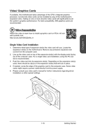
... case. For a single video card installation, using the PCI_E2 slot is recommended. 3. If needed, screw the edge of the motherboard's expansion slots. Video Demonstration Watch the video to learn how to the computer case. Remove any protective expansion slot covers from the...top of the expansion slot(s) with butterfly lock. For best compatibility, MSI graphics cards are recommended. Locate the expansion slot(s) on the motherboard. Chapter 1 Video/ Graphics Cards If available, this motherboard takes advantage of the CPU's integrate graphics processor, but discrete video ...
... case. For a single video card installation, using the PCI_E2 slot is recommended. 3. If needed, screw the edge of the motherboard's expansion slots. Video Demonstration Watch the video to learn how to the computer case. Remove any protective expansion slot covers from the...top of the expansion slot(s) with butterfly lock. For best compatibility, MSI graphics cards are recommended. Locate the expansion slot(s) on the motherboard. Chapter 1 Video/ Graphics Cards If available, this motherboard takes advantage of the CPU's integrate graphics processor, but discrete video ...

User Guide
Page 34
... drives (HDD), solid state drives (SSD), and optical drives (CD / DVD / Blu-Ray). However, it is a high-speed SATA interface port. Please refer to the motherboard for further installation instructions. • Please do not fold the SATA cable at a 90-degree angle. Refer to one SATA device. Each connector can connect...
... drives (HDD), solid state drives (SSD), and optical drives (CD / DVD / Blu-Ray). However, it is a high-speed SATA interface port. Please refer to the motherboard for further installation instructions. • Please do not fold the SATA cable at a 90-degree angle. Refer to one SATA device. Each connector can connect...

User Guide
Page 36
A system fan can be plugged into any fan blades. Some system fans may not connect to the motherboard and will instead connect to take advantage of the CPU fan control. Remember to connect all system fans, adapters are available to connect...up, ensure that there are not enough ports on -board, you must use a specially designed fan with +12V. If the motherboard has a System Hardware Monitor chipset on the motherboard to find recommended CPU heatsink. • These connectors support Smart Fan Control with liner mode. CPUFAN1/ 4.3S.pS2e.e+1en1.dsG2CerVoounntrdColPUFAN2 ...
A system fan can be plugged into any fan blades. Some system fans may not connect to the motherboard and will instead connect to take advantage of the CPU fan control. Remember to connect all system fans, adapters are available to connect...up, ensure that there are not enough ports on -board, you must use a specially designed fan with +12V. If the motherboard has a System Hardware Monitor chipset on the motherboard to find recommended CPU heatsink. • These connectors support Smart Fan Control with liner mode. CPUFAN1/ 4.3S.pS2e.e+1en1.dsG2CerVoounntrdColPUFAN2 ...

User Guide
Page 37
... MConnectors to the front panel switches and LEDs. Video Demonstration Watch the video to learn how to simplify installation. http://youtu.be plugged into the motherboard. Please use the optional M-Connector to Install front panel connectors. Plug all the wires from the case, pins marked by small triangles are positive wires...
... MConnectors to the front panel switches and LEDs. Video Demonstration Watch the video to learn how to simplify installation. http://youtu.be plugged into the motherboard. Please use the optional M-Connector to Install front panel connectors. Plug all the wires from the case, pins marked by small triangles are positive wires...

User Guide
Page 41
... to clear the CMOS RAM. 1 Keep Data 1 Clear Data Important You can automatically boot into the operating system (OS) every time it will damage the motherboard. 1-27 Getting Started Do not clear the CMOS RAM while the system is on because it is turned on the... motherboard to the TPM security platform manual for more details and usages. 2.34V.36S..3tS8aVe.n15Prd0iVaob1.NlwyP2I1o.eRopG4rwoPQ.rwGeionreurornudnd 1.L3P.L5CP.LCC7P.loLRC9cP.eLka1CsPd1e1ad.CtL3drPea.dLsdCrPsedasCr&...
... to clear the CMOS RAM. 1 Keep Data 1 Clear Data Important You can automatically boot into the operating system (OS) every time it will damage the motherboard. 1-27 Getting Started Do not clear the CMOS RAM while the system is on because it is turned on the... motherboard to the TPM security platform manual for more details and usages. 2.34V.36S..3tS8aVe.n15Prd0iVaob1.NlwyP2I1o.eRopG4rwoPQ.rwGeionreurornudnd 1.L3P.L5CP.LCC7P.loLRC9cP.eLka1CsPd1e1ad.CtL3drPea.dLsdCrPsedasCr&...
User Guide
Page 42
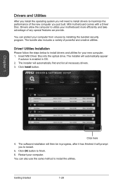
... to install drivers to maximize the performance of powerful and creative utilities. You can also use the same method to finish. 6. Insert MSI Driver Disc into the optical drive. Chapter 1 Click here 4. You can protect your computer. The bundle also includes a variety of ...28 Click Install button. Click OK button to install the utilities. Drivers allow the computer to install drivers and utilities for your motherboard more efficiently and take advantage of any special features we provide. Driver/ Utilities Installation Please follow the steps below to utilize your ...
... to install drivers to maximize the performance of powerful and creative utilities. You can also use the same method to finish. 6. Insert MSI Driver Disc into the optical drive. Chapter 1 Click here 4. You can protect your computer. The bundle also includes a variety of ...28 Click Install button. Click OK button to install the utilities. Drivers allow the computer to install drivers and utilities for your motherboard more efficiently and take advantage of any special features we provide. Driver/ Utilities Installation Please follow the steps below to utilize your ...

User Guide
Page 47
Motherboard Installation 1 Chapter 2 2 2-5 Quick Installation
Motherboard Installation 1 Chapter 2 2 2-5 Quick Installation


