
User Guide
Page 1
Preface X99S SLI PLUS Motherboard G52-78851X3
Preface X99S SLI PLUS Motherboard G52-78851X3

User Guide
Page 11
Preface ▍▍Contents Chapter 1 Getting Started 1-1 Packing Contents 1-2 Assembly Precautions 1-3 Motherboard Specifications 1-4 Block Diagram 1-7 Connectors Quick Guide 1-8 Back Panel Quick Guide 1-10 CPU (Central Processing Unit 1-12 Introduction to the LGA2011-3 CPU 1-12 CPU & Heatsink Installation 1-...
Preface ▍▍Contents Chapter 1 Getting Started 1-1 Packing Contents 1-2 Assembly Precautions 1-3 Motherboard Specifications 1-4 Block Diagram 1-7 Connectors Quick Guide 1-8 Back Panel Quick Guide 1-10 CPU (Central Processing Unit 1-12 Introduction to the LGA2011-3 CPU 1-12 CPU & Heatsink Installation 1-...

User Guide
Page 12
... Booting Jumper 1-32 Switch 1-33 BIOS1: Multi-BIOS Switch 1-33 Drivers and Utilities 1-34 Driver/ Utilities Installation 1-34 Chapter 2 Quick Installation 2-1 CPU Installation 2-2 Memory Installation 2-4 Motherboard Installation 2-5 Power Connectors Installation 2-7 SATA HDD Installation 2-9 M.2 module Installation 2-10 Front Panel Connector Installation 2-11 JFP1 Connector Installation 2-11 Front Panel Audio Connector Installation 2-11...
... Booting Jumper 1-32 Switch 1-33 BIOS1: Multi-BIOS Switch 1-33 Drivers and Utilities 1-34 Driver/ Utilities Installation 1-34 Chapter 2 Quick Installation 2-1 CPU Installation 2-2 Memory Installation 2-4 Motherboard Installation 2-5 Power Connectors Installation 2-7 SATA HDD Installation 2-9 M.2 module Installation 2-10 Front Panel Connector Installation 2-11 JFP1 Connector Installation 2-11 Front Panel Audio Connector Installation 2-11...

User Guide
Page 15
The X99S SLI PLUS Series motherboards are based on Intel® X99 chipset for choosing the X99S SLI PLUS Series (MS-7885 v1.X) ATX motherboard. Chapter 1 Getting Started Thank you for optimal system efficiency. Designed to fit the advanced Intel® LGA2011-3 processor, the X99S SLI PLUS Series motherboards deliver a high performance and professional desktop platform solution.
The X99S SLI PLUS Series motherboards are based on Intel® X99 chipset for choosing the X99S SLI PLUS Series (MS-7885 v1.X) ATX motherboard. Chapter 1 Getting Started Thank you for optimal system efficiency. Designed to fit the advanced Intel® LGA2011-3 processor, the X99S SLI PLUS Series motherboards deliver a high performance and professional desktop platform solution.

User Guide
Page 16
Packing Contents SATA9_10 SATA7_8 SATA3_4 SATA1_2 Motherboard Drivers & Utilities Disc Motherboard User Guide I/O Shield SATA Cable SLI Cable M-Connector * These pictures are for reference only and may vary without notice. * The packing contents may vary according to the model you purchased. Chapter 1 Getting Started 1-2
Packing Contents SATA9_10 SATA7_8 SATA3_4 SATA1_2 Motherboard Drivers & Utilities Disc Motherboard User Guide I/O Shield SATA Cable SLI Cable M-Connector * These pictures are for reference only and may vary without notice. * The packing contents may vary according to the model you purchased. Chapter 1 Getting Started 1-2

User Guide
Page 17
... component or fail to start. ■■Hold the motherboard by touching another metal object before handling the motherboard. ■■Store the motherboard in an electrostatic shielding container or on an antistatic pad whenever the motherboard is not installed. ■■Before turning on the ...avoid touching sensitive components. ■■It is recommended to wear an electrostatic discharge (ESD) wrist strap when handling the motherboard to damage from the power outlet before installation is completed. This could cause permanent damage to the components as well as injury...
... component or fail to start. ■■Hold the motherboard by touching another metal object before handling the motherboard. ■■Store the motherboard in an electrostatic shielding container or on an antistatic pad whenever the motherboard is not installed. ■■Before turning on the ...avoid touching sensitive components. ■■It is recommended to wear an electrostatic discharge (ESD) wrist strap when handling the motherboard to damage from the power outlet before installation is completed. This could cause permanent damage to the components as well as injury...

User Guide
Page 18
...ports on the back panel * Internal JUSB1 connector supports MSI Super Charger. ■■Realtek® ALC892 Codec -- 7.1-Channel High Definition Audio -- SATA1~6 support RAID 0, RAID 1, RAID 5 and RAID 10 -- Chapter 1 Motherboard Specifications CPU Support Chipset Memory Support Expansion Slots Multi-...Technology* ■■Supports 3-Way NVIDIA® SLI™ Technology * Supports Windows 7 and Windows 8/ 8.1 ■■Intel® X99 Express Chipset ■■10x SATA 6Gb/s ports (2x ports reserved for SATA Express port)* -- SATA7~10 ports only support IDE mode ...
...ports on the back panel * Internal JUSB1 connector supports MSI Super Charger. ■■Realtek® ALC892 Codec -- 7.1-Channel High Definition Audio -- SATA1~6 support RAID 0, RAID 1, RAID 5 and RAID 10 -- Chapter 1 Motherboard Specifications CPU Support Chipset Memory Support Expansion Slots Multi-...Technology* ■■Supports 3-Way NVIDIA® SLI™ Technology * Supports Windows 7 and Windows 8/ 8.1 ■■Intel® X99 Express Chipset ■■10x SATA 6Gb/s ports (2x ports reserved for SATA Express port)* -- SATA7~10 ports only support IDE mode ...

User Guide
Page 21
... 2.0 PCI Express Bus x1 x1 Intel I218 Gigabit LAN PCIe x1 slot PCI Express Bus 10 x SATA 6Gb/s (2 ports reserved for SATA Express) 6 x USB 3.0 6 x USB 2.0 X99 PCH x1 PCI Express Bus VIA VL805 4 x USB 3.0 LPC Bus x2 ASMEDIA ASM1042AE 2 x USB 3.0 (Gen2 x1) NV6792 Super I/O PS/2 Mouse / Keyboard Realtek ALC892 CS-Out...
... 2.0 PCI Express Bus x1 x1 Intel I218 Gigabit LAN PCIe x1 slot PCI Express Bus 10 x SATA 6Gb/s (2 ports reserved for SATA Express) 6 x USB 3.0 6 x USB 2.0 X99 PCH x1 PCI Express Bus VIA VL805 4 x USB 3.0 LPC Bus x2 ASMEDIA ASM1042AE 2 x USB 3.0 (Gen2 x1) NV6792 Super I/O PS/2 Mouse / Keyboard Realtek ALC892 CS-Out...

User Guide
Page 26
... to ensure the safety of thermal paste (or thermal tape) between the CPU and the heatsink to operate beyond product specifications. MSI does not guarantee the damages or risks caused by inadequate operation beyond product specifications is the Pin 1 indicator Alignment Key Chapter ...Overheating Overheating can tolerate overclocking. Getting Started 1-12 Always make sure that all other system components can seriously damage the CPU and motherboard. Before attempting to overclock, please make sure the cooling fans work properly to assist in correctly lining up the CPU for ...
... to ensure the safety of thermal paste (or thermal tape) between the CPU and the heatsink to operate beyond product specifications. MSI does not guarantee the damages or risks caused by inadequate operation beyond product specifications is the Pin 1 indicator Alignment Key Chapter ...Overheating Overheating can tolerate overclocking. Getting Started 1-12 Always make sure that all other system components can seriously damage the CPU and motherboard. Before attempting to overclock, please make sure the cooling fans work properly to assist in correctly lining up the CPU for ...

User Guide
Page 27
Video Demonstration Watch the video to learn how to prevent overheating and maintain system stability. You can damage both the CPU and the motherboard. A CPU heatsink is necessary to install CPU & heatsink. Wrong installation can identify the hinge lever as below to ensure correct CPU and heatsink installation. Open ...
Video Demonstration Watch the video to learn how to prevent overheating and maintain system stability. You can damage both the CPU and the motherboard. A CPU heatsink is necessary to install CPU & heatsink. Wrong installation can identify the hinge lever as below to ensure correct CPU and heatsink installation. Open ...

User Guide
Page 33
... Chapter 1 The I/O ports should line up with the holes on the mounting plate in your computer case. Mounting Screw Holes When installing the motherboard, first install the necessary mounting stands required for the mounting stands, is an I/O back plate that came with the computer case, please replace .... If there is prohibited. • Please make sure there are shown below. Align the mounting plate's mounting stands with the screw holes on the motherboard or within the computer case that may cause a short circuit of the computer case. The locations of the screw holes on the...
... Chapter 1 The I/O ports should line up with the holes on the mounting plate in your computer case. Mounting Screw Holes When installing the motherboard, first install the necessary mounting stands required for the mounting stands, is an I/O back plate that came with the computer case, please replace .... If there is prohibited. • Please make sure there are shown below. Align the mounting plate's mounting stands with the screw holes on the motherboard or within the computer case that may cause a short circuit of the computer case. The locations of the screw holes on the...

User Guide
Page 34
Getting Started 1-20 If done correctly, the clip on the motherboard's power connector. 1.G2.rG3o.urG4on.urdGonurdonudnd JPWR2 5.+61.+721.V+821.V+21V2V SATA9_10 SATA7_8 SATA3_4 SATA1_2 1.+23.+3.33.G4V.3.r+5Vo.5uG6Vn.r7+do.5uG8Vn.rP9do.Wu51nV0R1d.... and firmly press the cable into the connector. Chapter 1 Power Supply Video Demonstration Watch the video to learn how to ensure stable operation of the motherboard. http://youtu.be hooked on the power cable should be /gkDYyR_83I4 JPWR1~2: ATX Power Connectors These connectors allow you to connect an ATX power supply...
Getting Started 1-20 If done correctly, the clip on the motherboard's power connector. 1.G2.rG3o.urG4on.urdGonurdonudnd JPWR2 5.+61.+721.V+821.V+21V2V SATA9_10 SATA7_8 SATA3_4 SATA1_2 1.+23.+3.33.G4V.3.r+5Vo.5uG6Vn.r7+do.5uG8Vn.rP9do.Wu51nV0R1d.... and firmly press the cable into the connector. Chapter 1 Power Supply Video Demonstration Watch the video to learn how to ensure stable operation of the motherboard. http://youtu.be hooked on the power cable should be /gkDYyR_83I4 JPWR1~2: ATX Power Connectors These connectors allow you to connect an ATX power supply...

User Guide
Page 35
Chapter 1 Expansion Slots This motherboard contains numerous slots for [M.2 PCIE] in BIOS. PCI_E1~6: PCIe Expansion Slots The PCIe slot supports the PCIe interface expansion card. Important • For a single PCIe ...
Chapter 1 Expansion Slots This motherboard contains numerous slots for [M.2 PCIE] in BIOS. PCI_E1~6: PCIe Expansion Slots The PCIe slot supports the PCIe interface expansion card. Important • For a single PCIe ...

User Guide
Page 36
...will lock in place. 4. Some video cards might require a power cable directly from the computer case. 2. Adding on the motherboard. Push the video card into its expansion slot(s). Video Demonstration Watch the video to learn how to the computer case. Please consult... card installation, using the PCI_E1 slot is recommended. 3. Getting Started 1-22 For best compatibility, MSI graphics cards are recommended. Chapter 1 Video/ Graphics Cards If available, this motherboard takes advantage of the CPU's integrate graphics processor, but discrete video cards can be installed by ...
...will lock in place. 4. Some video cards might require a power cable directly from the computer case. 2. Adding on the motherboard. Push the video card into its expansion slot(s). Video Demonstration Watch the video to learn how to the computer case. Please consult... card installation, using the PCI_E1 slot is recommended. 3. Getting Started 1-22 For best compatibility, MSI graphics cards are recommended. Chapter 1 Video/ Graphics Cards If available, this motherboard takes advantage of the CPU's integrate graphics processor, but discrete video cards can be installed by ...

User Guide
Page 37
... Data loss may result during transmission otherwise. • SATA cables have identical plugs on either sides of the cable. http://youtu.be connected to the motherboard for further installation instructions. • Please do not fold the SATA cable at a 90-degree angle. Such devices include disk drives (HDD), solid state drives...
... Data loss may result during transmission otherwise. • SATA cables have identical plugs on either sides of the cable. http://youtu.be connected to the motherboard for further installation instructions. • Please do not fold the SATA cable at a 90-degree angle. Such devices include disk drives (HDD), solid state drives...

User Guide
Page 39
...to automatically control the fan speeds according to connect all system fans. Some system fans may not connect to the motherboard and will instead connect to find recommended CPU heatsink. • These connectors support Smart Fan Control with +12V. If the... motherboard has a System Hardware Monitor chipset on the motherboard to the CPU's and system's temperature. • If there are no cables impeding any available system fan connector. SATA9_10 ...
...to automatically control the fan speeds according to connect all system fans. Some system fans may not connect to the motherboard and will instead connect to find recommended CPU heatsink. • These connectors support Smart Fan Control with +12V. If the... motherboard has a System Hardware Monitor chipset on the motherboard to the CPU's and system's temperature. • If there are no cables impeding any available system fan connector. SATA9_10 ...

User Guide
Page 40
... the M-Connector into JFP1. Video Demonstration Watch the video to learn how to the front panel switches and LEDs. http://youtu.be plugged into the motherboard. Getting Started 1-26 The JFP1 connector is compliant with the Intel® Front Panel I/O Connectivity Design Guide. When installing the front panel connectors, please use...
... the M-Connector into JFP1. Video Demonstration Watch the video to learn how to the front panel switches and LEDs. http://youtu.be plugged into the motherboard. Getting Started 1-26 The JFP1 connector is compliant with the Intel® Front Panel I/O Connectivity Design Guide. When installing the front panel connectors, please use...
User Guide
Page 41
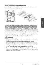
...which provides quicker USB charging of your smartphone or other USB-powered devices. To enable this feature, please install the MSI Super-Charger application on select MSI motherboard models. When the Super-Charger application is backward compatible with USB 2.0 devices. To enable the JUSB1 connector to 5Gbits...transfer rates up to function as a normal USB 3.0 connector, please turn off the Super-Charger application. Please refer to the MSI website to check if your motherboard has Super-Charger technology. • For iPad, JUSB1 (red mark) can still charge iPad in S3, S4, S5 state...
...which provides quicker USB charging of your smartphone or other USB-powered devices. To enable this feature, please install the MSI Super-Charger application on select MSI motherboard models. When the Super-Charger application is backward compatible with USB 2.0 devices. To enable the JUSB1 connector to 5Gbits...transfer rates up to function as a normal USB 3.0 connector, please turn off the Super-Charger application. Please refer to the MSI website to check if your motherboard has Super-Charger technology. • For iPad, JUSB1 (red mark) can still charge iPad in S3, S4, S5 state...
User Guide
Page 44
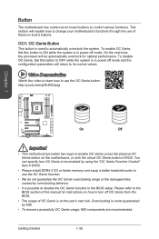
.... • It is possible to use of OC Genie is in BIOS. You can specify how OC Genie to be enabled by MSI. • To ensure successfully OC Genie usage, MSI components are recommended. OC1: OC Genie Button This button is used to ON while the system is at the user's own... instructions on -board buttons. On the next boot, the processor will explain how to enable OC Genie: press the physical OC Genie button on the motherboard, or click the virtual OC Genie button in power off OC Genie from the BIOS. • The usage of these on how to turn off...
.... • It is possible to use of OC Genie is in BIOS. You can specify how OC Genie to be enabled by MSI. • To ensure successfully OC Genie usage, MSI components are recommended. OC1: OC Genie Button This button is used to ON while the system is at the user's own... instructions on -board buttons. On the next boot, the processor will explain how to enable OC Genie: press the physical OC Genie button on the motherboard, or click the virtual OC Genie button in power off OC Genie from the BIOS. • The usage of these on how to turn off...

User Guide
Page 46
...overclocking results will try extreme low temperature overclocking at a stable processor frequency and to prevent the system from a battery located on the motherboard to save system configuration data. Afterwards, open the jumper . JSLOW1: Slow Mode Booting Jumper This jumper is off or the system will ...damage the motherboard. Jumper JBAT1: Clear CMOS Jumper There is CMOS RAM onboard that provides the extreme overclocking conditions, to boot at their own risks....
...overclocking results will try extreme low temperature overclocking at a stable processor frequency and to prevent the system from a battery located on the motherboard to save system configuration data. Afterwards, open the jumper . JSLOW1: Slow Mode Booting Jumper This jumper is off or the system will ...damage the motherboard. Jumper JBAT1: Clear CMOS Jumper There is CMOS RAM onboard that provides the extreme overclocking conditions, to boot at their own risks....


