User Manual
Page 16
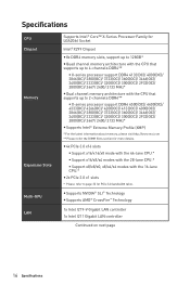
y Supports NVIDIA® SLI™ Technology y Supports AMD® CrossFire™ Technology 1x Intel I219-V Gigabit LAN controller 1x Intel I211 Gigabit LAN controller Continued on next page 16 Specifications Specifications CPU Chipset Memory Expansion Slots Multi-GPU LAN Supports Intel® Core™ X-Series Processor Family for LGA2066 Socket Intel® X299 Chipset y 8x...
y Supports NVIDIA® SLI™ Technology y Supports AMD® CrossFire™ Technology 1x Intel I219-V Gigabit LAN controller 1x Intel I211 Gigabit LAN controller Continued on next page 16 Specifications Specifications CPU Chipset Memory Expansion Slots Multi-GPU LAN Supports Intel® Core™ X-Series Processor Family for LGA2066 Socket Intel® X299 Chipset y 8x...

User Manual
Page 17
... through the internal USB connector) y ASMedia® ASM1074 Hub ƒ 3x USB 3.1 Gen1 (SuperSpeed USB) ports on the back panel y Intel® X299 Chipset ƒ 5x USB 3.1 Gen1 (SuperSpeed USB) ports (1 Type-A port on the back panel, 4 ports available through the internal USB connectors) ƒ... back panel, 4 ports available through the internal USB connectors) Continued on the CPU. Please refer to PCIe 3.0 x4 and SATA 6Gb/s ƒ M2_1 slot supports 2242/ 2260 /2280 storage devices ƒ M2_2 slot supports 2242/ 2260 /2280/ 22110 storage devices ƒ Intel® Optane™...
... through the internal USB connector) y ASMedia® ASM1074 Hub ƒ 3x USB 3.1 Gen1 (SuperSpeed USB) ports on the back panel y Intel® X299 Chipset ƒ 5x USB 3.1 Gen1 (SuperSpeed USB) ports (1 Type-A port on the back panel, 4 ports available through the internal USB connectors) ƒ... back panel, 4 ports available through the internal USB connectors) Continued on the CPU. Please refer to PCIe 3.0 x4 and SATA 6Gb/s ƒ M2_1 slot supports 2242/ 2260 /2280 storage devices ƒ M2_2 slot supports 2242/ 2260 /2280/ 22110 storage devices ƒ Intel® Optane™...

User Manual
Page 18
... main power connector y 1x 8-pin ATX 12V power connector y 8x SATA 6Gb/s connectors y 2x USB 2.0 connectors (supports additional 4 USB 2.0 ports) y 2x USB 3.1 Gen1 connectors (supports additional 4 USB 3.1 Gen1 ports) y 1x USB 3.1 Gen2 Type-C port y 1x 4-pin CPU fan connector y 1x 4-pin Water Pump connector y 4x 4-pin system fan connectors y 2x Front panel connectors...
... main power connector y 1x 8-pin ATX 12V power connector y 8x SATA 6Gb/s connectors y 2x USB 2.0 connectors (supports additional 4 USB 2.0 ports) y 2x USB 3.1 Gen1 connectors (supports additional 4 USB 3.1 Gen1 ports) y 1x USB 3.1 Gen2 Type-C port y 1x 4-pin CPU fan connector y 1x 4-pin Water Pump connector y 4x 4-pin system fan connectors y 2x Front panel connectors...

User Manual
Page 19
... Factor BIOS Features Software y Realtek® ALC1220 Codec y 7.1-Channel High Definition Audio y Supports S/PDIF output NUVOTON NCT6795 Controller Chip y CPU/System temperature detection y CPU/System fan speed detection y CPU/System fan speed control y ATX Form Factor y 12 in . (30.5 cm x ...LIVE UPDATE 6 y SMART TOOL y X-BOOST y SUPER CHARGER y MYSTIC LIGHT y RAMDISK y NETWORK MANAGER y DPC LATENCY TUNER y FAST BOOST y CPU-Z MSI GAMING y Intel Extreme Tuning Utility y Norton™ Internet Security Solution y Google Chrome™ ,Google Toolbar, Google Drive Continued on next page Speci&#...
... Factor BIOS Features Software y Realtek® ALC1220 Codec y 7.1-Channel High Definition Audio y Supports S/PDIF output NUVOTON NCT6795 Controller Chip y CPU/System temperature detection y CPU/System fan speed detection y CPU/System fan speed control y ATX Form Factor y 12 in . (30.5 cm x ...LIVE UPDATE 6 y SMART TOOL y X-BOOST y SUPER CHARGER y MYSTIC LIGHT y RAMDISK y NETWORK MANAGER y DPC LATENCY TUNER y FAST BOOST y CPU-Z MSI GAMING y Intel Extreme Tuning Utility y Norton™ Internet Security Solution y Google Chrome™ ,Google Toolbar, Google Drive Continued on next page Speci&#...

User Manual
Page 28
... to operate beyond product specifications. 28 Overview of Components y Whenever the CPU is designed to support overclocking. Before attempting to overclock, please make sure the cooling fans work properly to protect the CPU from the power outlet before booting your system. MSI® does not guarantee the damages or risks caused by covering the...
... to operate beyond product specifications. 28 Overview of Components y Whenever the CPU is designed to support overclocking. Before attempting to overclock, please make sure the cooling fans work properly to protect the CPU from the power outlet before booting your system. MSI® does not guarantee the damages or risks caused by covering the...

User Manual
Page 29
Red = 8 DIMMs support (4-channels architecture CPU) White = 4 DIMMs support (2-channels architecture CPU) B1B2A1A2 C2C1D2D1 Memory module installation recommendation (4-Channels architecture CPU ) 1 DIMM 2 DIMMs 3 DIMMs 4 DIMMs 5 DIMMs 6 DIMMs 7 DIMMs 8 DIMMs B1 B2 A1 A2 Intel Core X-series CPU Supports 4-channels memory architecture C2 C1 D2 D1 DIMMC1 DIMMA1 DIMMC1 Overview of Components 29 DIMM Slots S/K LED : S/K LED indicates that the installed CPU supports either 4-channels or 2-channels memory architecture.
Red = 8 DIMMs support (4-channels architecture CPU) White = 4 DIMMs support (2-channels architecture CPU) B1B2A1A2 C2C1D2D1 Memory module installation recommendation (4-Channels architecture CPU ) 1 DIMM 2 DIMMs 3 DIMMs 4 DIMMs 5 DIMMs 6 DIMMs 7 DIMMs 8 DIMMs B1 B2 A1 A2 Intel Core X-series CPU Supports 4-channels memory architecture C2 C1 D2 D1 DIMMC1 DIMMA1 DIMMC1 Overview of Components 29 DIMM Slots S/K LED : S/K LED indicates that the installed CPU supports either 4-channels or 2-channels memory architecture.

User Manual
Page 31
Memory module installation recommendation (2-Channels architecture CPU ) B1 B2 A1 A2 1 DIMM 2 DIMMs 3 DIMMs 4 DIMMs DIMMB1, B2, A1 and A2 are un-available Intel Core X-series CPU Supports 2-channels memory architecture C2 C1 D2 D1 DIMMC1 DIMMD1 DIMMC1 DIMMD1 DIMMC1 DIMMC2 DIMMD1 DIMMD2 DIMMC1 DIMMC2 Overview of Components 31
Memory module installation recommendation (2-Channels architecture CPU ) B1 B2 A1 A2 1 DIMM 2 DIMMs 3 DIMMs 4 DIMMs DIMMB1, B2, A1 and A2 are un-available Intel Core X-series CPU Supports 2-channels memory architecture C2 C1 D2 D1 DIMMC1 DIMMD1 DIMMC1 DIMMD1 DIMMC1 DIMMC2 DIMMD1 DIMMD2 DIMMC1 DIMMC2 Overview of Components 31

User Manual
Page 55
...LED starts flashing. 6. Press the Flash BIOS Button to install CPU and memory.) 4. Please download the latest BIOS file that contains the MSI.ROM file into the Flash BIOS Port on the drive icon and... to the root of your USB flash drive (FAT32 format). 3. To check your motherboard model from the MSI® website. 2. Plug the USB flash drive that matches your drive, go to Windows Explorer, right ...BIOS with Flash BIOS Button 1. Rename the BIOS file to MSI.ROM, and save it to Properties. Important Only the FAT32 format USB flash drive supports updating BIOS by Flash BIOS Button.
...LED starts flashing. 6. Press the Flash BIOS Button to install CPU and memory.) 4. Please download the latest BIOS file that contains the MSI.ROM file into the Flash BIOS Port on the drive icon and... to the root of your USB flash drive (FAT32 format). 3. To check your motherboard model from the MSI® website. 2. Plug the USB flash drive that matches your drive, go to Windows Explorer, right ...BIOS with Flash BIOS Button 1. Rename the BIOS file to MSI.ROM, and save it to Properties. Important Only the FAT32 format USB flash drive supports updating BIOS by Flash BIOS Button.

User Manual
Page 56
... load defaults to change the boot priority. y XMP switch - profile. y Setup Mode switch - y Screenshot - shows the CPU/ DDR speed, CPU/ MB temperature, MB/ CPU type, memory size, CPU/ DDR voltage, BIOS version and build date. you can move the device icons to keep the optimal performance and system stability...the F6, F10 and F12 function keys are available. press this tab or the F7 key to find the item listing. y Language - supported memory module is left to exit search page. It allows you to search by pressing the Setup Mode switch or F7 function key. allows...
... load defaults to change the boot priority. y XMP switch - profile. y Setup Mode switch - y Screenshot - shows the CPU/ DDR speed, CPU/ MB temperature, MB/ CPU type, memory size, CPU/ DDR voltage, BIOS version and build date. you can move the device icons to keep the optimal performance and system stability...the F6, F10 and F12 function keys are available. press this tab or the F7 key to find the item listing. y Language - supported memory module is left to exit search page. It allows you to search by pressing the Setup Mode switch or F7 function key. allows...
User Manual
Page 67
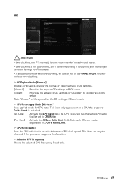
... y Overclocking your hardware. y Overclocking is used to show the normal or expert version of Expert mode. f OC Explore Mode [Normal] Enables or disables to determine CPU clock speed. f CPU Ratio [Auto] Sets the CPU ratio that be changed if the processor supports this function. BIOS Setup 67
... y Overclocking your hardware. y Overclocking is used to show the normal or expert version of Expert mode. f OC Explore Mode [Normal] Enables or disables to determine CPU clock speed. f CPU Ratio [Auto] Sets the CPU ratio that be changed if the processor supports this function. BIOS Setup 67
User Manual
Page 68
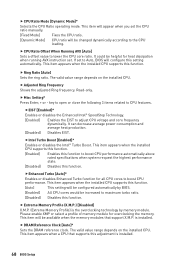
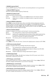
... a offset value to maximum turbo ratio. [Disabled] Disables this setting automatically. f Adjusted Ring Frequency Shows the adjusted Ring frequency. This item appears when the installed CPU supports this function. [Auto] This setting will configure this function. fEIST [Enabled]* Enables or disables the Enhanced Intel® SpeedStep Technology. [Enabled] Enables the EIST to...
... a offset value to maximum turbo ratio. [Disabled] Disables this setting automatically. f Adjusted Ring Frequency Shows the adjusted Ring frequency. This item appears when the installed CPU supports this function. [Auto] This setting will configure this function. fEIST [Enabled]* Enables or disables the Enhanced Intel® SpeedStep Technology. [Enabled] Enables the EIST to...
User Manual
Page 69
...SVID Communication [Auto]* Enables or disables SVID (Serial Voltage Identification) support. [Auto] [Enabled] [Disabled] This setting will be configured automatically by BIOS. BIOS Setup 69 If set to memory. f VCCIN Voltage [Auto] Sets the CPU input voltage. If set to Auto, BIOS will set these ... clear the CMOS data, and enter the BIOS to configure the DRAM timing for memory. Disables SVID (Serial Voltage Identification) support. If set to CPU. f DRAM Voltages control [Auto] These options allows you to set the voltages related to Auto, BIOS will be configured ...
...SVID Communication [Auto]* Enables or disables SVID (Serial Voltage Identification) support. [Auto] [Enabled] [Disabled] This setting will be configured automatically by BIOS. BIOS Setup 69 If set to memory. f VCCIN Voltage [Auto] Sets the CPU input voltage. If set to Auto, BIOS will set these ... clear the CMOS data, and enter the BIOS to configure the DRAM timing for memory. Disables SVID (Serial Voltage Identification) support. If set to CPU. f DRAM Voltages control [Auto] These options allows you to set the voltages related to Auto, BIOS will be configured ...
User Manual
Page 70
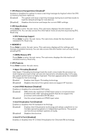
...as multiple systems virtually. [Disabled] Disables this information menu at any time by pressing [F4]. This item appears when the installed CPU supports this technology. [Enable] Enables Intel Hyper-Threading technology. [Disabled] Disables this way, the system performance is highly improved. In... this item if the system does not support HT function. The sub-menu displays the information of installed memory. Read only. f CPU Memory Changed Detect [Enabled]* Enables or disables the system to issue a warning message during...
...as multiple systems virtually. [Disabled] Disables this information menu at any time by pressing [F4]. This item appears when the installed CPU supports this technology. [Enable] Enables Intel Hyper-Threading technology. [Disabled] Disables this way, the system performance is highly improved. In... this item if the system does not support HT function. The sub-menu displays the information of installed memory. Read only. f CPU Memory Changed Detect [Enabled]* Enables or disables the system to issue a warning message during...

User Manual
Page 71
...Auto] This setting will be configured automatically by BIOS. [Enabled] Detects the idle state of C-state depend on the installed CPU. fC1E Support [Disabled] Enables or disables the C1E function for power-saving in halt state. This item appears when Intel C-State is...the specific application. [Disabled] Enables the requested cache line only. This item appears when a CPU supports this function. fAdjacent Cache Line Prefetch [Enabled] Enables or disables the CPU hardware prefetcher (MLC Spatial prefetcher). [Enabled] Enables adjacent cache line prefetching for reducing the cache ...
...Auto] This setting will be configured automatically by BIOS. [Enabled] Detects the idle state of C-state depend on the installed CPU. fC1E Support [Disabled] Enables or disables the C1E function for power-saving in halt state. This item appears when Intel C-State is...the specific application. [Disabled] Enables the requested cache line only. This item appears when a CPU supports this function. fAdjacent Cache Line Prefetch [Enabled] Enables or disables the CPU hardware prefetcher (MLC Spatial prefetcher). [Enabled] Enables adjacent cache line prefetching for reducing the cache ...

User Manual
Page 103
...; Click Yes in BIOS. WARNING Once you enable Intel® Optane™ memory, in order to older version of the BIOS. y DO NOT replace the CPU that is not supported by Intel® Optane™ Memory. Intel® Optane™ Memory Configuration 103
...; Click Yes in BIOS. WARNING Once you enable Intel® Optane™ memory, in order to older version of the BIOS. y DO NOT replace the CPU that is not supported by Intel® Optane™ Memory. Intel® Optane™ Memory Configuration 103


