
User Manual
Page 13
... Information 2 Quick Start ...3 Preparing Tools and Components 3 Installing a Processor 4 Installing DDR4 memory 5 Connecting the Front Panel Header 6 Installing the Motherboard 7 Installing SATA Drives 8 Installing a Graphics Card 9 Connecting Peripheral Devices 10 Connecting the Power Connectors 11 Power On...12 Specifications...16 Block Diagram ...22 Rear I/O Panel...23 LAN Port LED Status Table 23 Audio Ports Configuration 23 Realtek HD Audio Manager 24 Overview of Components 26 CPU Socket ...28 DIMM Slots...29 PCI_E1~6: PCIe Expansion Slots 32 PCIe slots bandwidth table 32...
... Information 2 Quick Start ...3 Preparing Tools and Components 3 Installing a Processor 4 Installing DDR4 memory 5 Connecting the Front Panel Header 6 Installing the Motherboard 7 Installing SATA Drives 8 Installing a Graphics Card 9 Connecting Peripheral Devices 10 Connecting the Power Connectors 11 Power On...12 Specifications...16 Block Diagram ...22 Rear I/O Panel...23 LAN Port LED Status Table 23 Audio Ports Configuration 23 Realtek HD Audio Manager 24 Overview of Components 26 CPU Socket ...28 DIMM Slots...29 PCI_E1~6: PCIe Expansion Slots 32 PCIe slots bandwidth table 32...
User Manual
Page 14
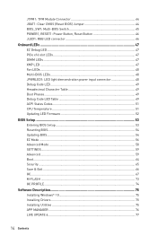
... Multi-BIOS LEDs 48 JPWRLED1: LED light demonstration power input connector 48 Debug Code LED 49 Hexadecimal Character Table 49 Boot Phases...49 Debug Code LED Table 49 ACPI States Codes 51 CPU Temperature 51 Updating LED Firmware 52 BIOS Setup ...53 Entering BIOS Setup 53 Resetting BIOS...54 Updating BIOS...54 EZ Mode ...56 Advanced Mode ...58 SETTINGS...59 Advanced...59 Boot...64 Security ...65 Save & Exit...66 OC...67 M-FLASH ...73 OC PROFILE ...74 Software Description 75 Installing Windows® 10 75 Installing Drivers 75 Installing Utilities...
... Multi-BIOS LEDs 48 JPWRLED1: LED light demonstration power input connector 48 Debug Code LED 49 Hexadecimal Character Table 49 Boot Phases...49 Debug Code LED Table 49 ACPI States Codes 51 CPU Temperature 51 Updating LED Firmware 52 BIOS Setup ...53 Entering BIOS Setup 53 Resetting BIOS...54 Updating BIOS...54 EZ Mode ...56 Advanced Mode ...58 SETTINGS...59 Advanced...59 Boot...64 Security ...65 Save & Exit...66 OC...67 M-FLASH ...73 OC PROFILE ...74 Software Description 75 Installing Windows® 10 75 Installing Drivers 75 Installing Utilities...

User Manual
Page 17
... internal USB connectors) ƒ 8x USB 2.0 (High-speed USB) ports (4 Type-A ports on the back panel, 4 ports available through the internal USB connectors) Continued on the CPU. Please refer to PCIe 3.0 x4 and SATA 6Gb/s ƒ M2_1 slot supports 2242/ 2260 /2280 storage devices ƒ M2_2 slot supports 2242/ 2260 /2280/ 22110 storage devices ƒ Intel® Optane™ Memory Ready for all M.2 slots ** y 1x U.2 port *** ƒ Supports PCIe 3.0 x4 NVMe storage y Supports Intel® Smart Response Technology **** * M.2 slots and SATA ports share the same bandwidth. Storage RAID USB...
... internal USB connectors) ƒ 8x USB 2.0 (High-speed USB) ports (4 Type-A ports on the back panel, 4 ports available through the internal USB connectors) Continued on the CPU. Please refer to PCIe 3.0 x4 and SATA 6Gb/s ƒ M2_1 slot supports 2242/ 2260 /2280 storage devices ƒ M2_2 slot supports 2242/ 2260 /2280/ 22110 storage devices ƒ Intel® Optane™ Memory Ready for all M.2 slots ** y 1x U.2 port *** ƒ Supports PCIe 3.0 x4 NVMe storage y Supports Intel® Smart Response Technology **** * M.2 slots and SATA ports share the same bandwidth. Storage RAID USB...

User Manual
Page 18
... 8x SATA 6Gb/s connectors y 2x USB 2.0 connectors (supports additional 4 USB 2.0 ports) y 2x USB 3.1 Gen1 connectors (supports additional 4 USB 3.1 Gen1 ports) y 1x USB 3.1 Gen2 Type-C port y 1x 4-pin CPU fan connector y 1x 4-pin Water Pump connector y 4x 4-pin system fan connectors y 2x Front panel connectors y 1x Front panel audio connector y 1x RGB LED connector y 1x TPM module connector y 1x Virtual RAID on CPU connector y 1x Thunderbolt add-on card connector y 1x Power button y 1x Reset button Switches Jumper Debug LED y 1x Multi-BIOS switch y 1x Clear CMOS jumper y 1x Chassis Intrusion...
... 8x SATA 6Gb/s connectors y 2x USB 2.0 connectors (supports additional 4 USB 2.0 ports) y 2x USB 3.1 Gen1 connectors (supports additional 4 USB 3.1 Gen1 ports) y 1x USB 3.1 Gen2 Type-C port y 1x 4-pin CPU fan connector y 1x 4-pin Water Pump connector y 4x 4-pin system fan connectors y 2x Front panel connectors y 1x Front panel audio connector y 1x RGB LED connector y 1x TPM module connector y 1x Virtual RAID on CPU connector y 1x Thunderbolt add-on card connector y 1x Power button y 1x Reset button Switches Jumper Debug LED y 1x Multi-BIOS switch y 1x Clear CMOS jumper y 1x Chassis Intrusion...
User Manual
Page 50
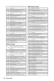
... specific) ACPI module initialization CSM initialization Reserved for future AMI DXE codes Boot Device Selection (BDS) phase is started Driver connecting is started PCI Bus initialization is started PCI Bus Hot Plug Controller Initialization PCI Bus Enumeration 32 PCI Bus Request Resources PCI Bus Assign Resources Console Output devices connect Console input devices connect Super IO Initialization USB initialization is started USB Reset USB Detect USB Enable Reserved for future AMI codes IDE initialization is started IDE Reset IDE Detect IDE Enable SCSI initialization is started PEI Error...
... specific) ACPI module initialization CSM initialization Reserved for future AMI DXE codes Boot Device Selection (BDS) phase is started Driver connecting is started PCI Bus initialization is started PCI Bus Hot Plug Controller Initialization PCI Bus Enumeration 32 PCI Bus Request Resources PCI Bus Assign Resources Console Output devices connect Console input devices connect Super IO Initialization USB initialization is started USB Reset USB Detect USB Enable Reserved for future AMI codes IDE initialization is started IDE Reset IDE Detect IDE Enable SCSI initialization is started PEI Error...
User Manual
Page 51
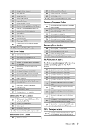
... future AMI error codes Recovery Progress Codes F0 F1 F2 F3 F4 F5 - A8 Setup Verifying Password A9 Start of Setup AB Setup Input Wait AD Ready To Boot event AE Legacy Boot event AF Exit Boot Services event B0 Runtime Set Virtual Address MAP Begin B1 Runtime Set Virtual Address MAP End B2 Legacy Option ROM Initialization B3 System Reset B4 USB hot plug B5 PCI bus hot plug B6 Clean-up from the S3 sleep 30...
... future AMI error codes Recovery Progress Codes F0 F1 F2 F3 F4 F5 - A8 Setup Verifying Password A9 Start of Setup AB Setup Input Wait AD Ready To Boot event AE Legacy Boot event AF Exit Boot Services event B0 Runtime Set Virtual Address MAP Begin B1 Runtime Set Virtual Address MAP End B2 Legacy Option ROM Initialization B3 System Reset B4 USB hot plug B5 PCI bus hot plug B6 Clean-up from the S3 sleep 30...
User Manual
Page 54
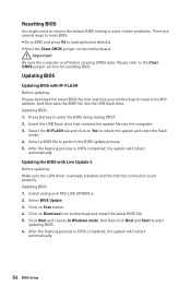
... Start to load optimized defaults. y Short the Clear CMOS jumper on Scan button. 4. After the flashing process is off before clearing CMOS data. Important Be sure the computer is 100% completed, the system will reboot automatically. Insert the USB flash drive that matches your motherboard model from MSI website. Install and launch MSI LIVE UPDATE 6. 2. Select BIOS Update. 3. Updating BIOS: 1. Updating the BIOS with M-FLASH Before updating: Please download the latest BIOS file that contains the update file into the USB flash drive. Click on the motherboard...
... Start to load optimized defaults. y Short the Clear CMOS jumper on Scan button. 4. After the flashing process is off before clearing CMOS data. Important Be sure the computer is 100% completed, the system will reboot automatically. Insert the USB flash drive that matches your motherboard model from MSI website. Install and launch MSI LIVE UPDATE 6. 2. Select BIOS Update. 3. Updating BIOS: 1. Updating the BIOS with M-FLASH Before updating: Please download the latest BIOS file that contains the update file into the USB flash drive. Click on the motherboard...

User Manual
Page 55
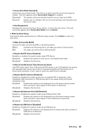
... drive, go to Properties. Press the Flash BIOS Button to install CPU and memory.) 4. Important Only the FAT32 format USB flash drive supports updating BIOS by Flash BIOS Button. To check your USB flash drive (FAT32 format). 3. Please download the latest BIOS file that contains the MSI.ROM file into the Flash BIOS Port on the drive icon and go to Windows Explorer, right click on the rear I/O panel. 5. BIOS Setup 55 Updating BIOS with Flash BIOS Button 1. Connect the power supply to CPU_PWR1 and ATX_PWR1. (No need to flash BIOS, and the LED starts flashing...
... drive, go to Properties. Press the Flash BIOS Button to install CPU and memory.) 4. Important Only the FAT32 format USB flash drive supports updating BIOS by Flash BIOS Button. To check your USB flash drive (FAT32 format). 3. Please download the latest BIOS file that contains the MSI.ROM file into the Flash BIOS Port on the drive icon and go to Windows Explorer, right click on the rear I/O panel. 5. BIOS Setup 55 Updating BIOS with Flash BIOS Button 1. Connect the power supply to CPU_PWR1 and ATX_PWR1. (No need to flash BIOS, and the LED starts flashing...

User Manual
Page 56
... the mouse to switch between Advanced mode and EZ mode. y Boot device priority bar - XMP switch Setup Mode switch Screenshot Search Language System information OC GENIE 4 switch Information display Boot device priority bar M-Flash Favorites Hardware Monitor Function buttons y OC GENIE 4 switch - y XMP switch - supported memory module is left to right. 56 BIOS Setup y Screenshot - It allows you to select the language of BIOS setup. shows the CPU/ DDR speed, CPU/ MB temperature, MB/ CPU type, memory size, CPU/ DDR voltage, BIOS version and build date...
... the mouse to switch between Advanced mode and EZ mode. y Boot device priority bar - XMP switch Setup Mode switch Screenshot Search Language System information OC GENIE 4 switch Information display Boot device priority bar M-Flash Favorites Hardware Monitor Function buttons y OC GENIE 4 switch - y XMP switch - supported memory module is left to right. 56 BIOS Setup y Screenshot - It allows you to select the language of BIOS setup. shows the CPU/ DDR speed, CPU/ MB temperature, MB/ CPU type, memory size, CPU/ DDR voltage, BIOS version and build date...

User Manual
Page 57
enable or disable the LAN Option ROM, M.2/Optane Genie, Hardcore Mode, AHCI, RAID, CPU Fan Fail Warning Control and BIOS Log Review by percentage. y M-Flash - SETTINGS, OC...,etc) as the BIOS home page. ƒ Favorite1~5 - Right-click or press F2 key. 3. click on favorite page (Favorite 1~5) 2. press the Favorites tab or the F3 key to update BIOS with a USB flash drive. Move the mouse over a BIOS item on this button to display the Hardware Monitor menu that provides the...
enable or disable the LAN Option ROM, M.2/Optane Genie, Hardcore Mode, AHCI, RAID, CPU Fan Fail Warning Control and BIOS Log Review by percentage. y M-Flash - SETTINGS, OC...,etc) as the BIOS home page. ƒ Favorite1~5 - Right-click or press F2 key. 3. click on favorite page (Favorite 1~5) 2. press the Favorites tab or the F3 key to update BIOS with a USB flash drive. Move the mouse over a BIOS item on this button to display the Hardware Monitor menu that provides the...

User Manual
Page 60
... when Onboard LAN Controller is enabled. [Enabled] Enables the Ipv4 PXE boot support. [Disabled] Disables the Ipv4 PXE boot support. 60 BIOS Setup This item will be decoded in above 4G address space. fPEGX - Max Link Speed [Auto] Sets PCI Express protocol of PCI interface device. [Options: 32, 64, 96, 128, 160, 192, 224, 248 PCI Bus clocks] fAbove 4G memory/ Crypto Currency mining [Disabled] Enables or disables 64-bit capable devices to utilize more than 4x GPUs. [Disabled] Disables this function. f ACPI Settings Sets ACPI parameters of the onboard Power LED. [Dual...
... when Onboard LAN Controller is enabled. [Enabled] Enables the Ipv4 PXE boot support. [Disabled] Disables the Ipv4 PXE boot support. 60 BIOS Setup This item will be decoded in above 4G address space. fPEGX - Max Link Speed [Auto] Sets PCI Express protocol of PCI interface device. [Options: 32, 64, 96, 128, 160, 192, 224, 248 PCI Bus clocks] fAbove 4G memory/ Crypto Currency mining [Disabled] Enables or disables 64-bit capable devices to utilize more than 4x GPUs. [Disabled] Disables this function. f ACPI Settings Sets ACPI parameters of the onboard Power LED. [Dual...

User Manual
Page 61
...AHCI mode for the SATA ports. BIOS Setup 61 AHCI (Advanced Host Controller Interface) offers some advanced features to enable or disable the SATA hot plug support. [Enabled] Enables hot plug support for the SATA ports. [Disabled] Disables hot plug support for SATA storage devices. fHD Audio Controller [Enabled] Enables or disables the onboard High Definition Audio controller. fXHCI Hand-off [Diasbled] Enables or disables XHCI hand-off feature. fSATA Mode [AHCI Mode] Sets the operation mode of EuP2013 and AC Power Loss behaviors. fSATAx Hot Plug [Disabled] Allows user...
...AHCI mode for the SATA ports. BIOS Setup 61 AHCI (Advanced Host Controller Interface) offers some advanced features to enable or disable the SATA hot plug support. [Enabled] Enables hot plug support for the SATA ports. [Disabled] Disables hot plug support for SATA storage devices. fHD Audio Controller [Enabled] Enables or disables the onboard High Definition Audio controller. fXHCI Hand-off [Diasbled] Enables or disables XHCI hand-off feature. fSATA Mode [AHCI Mode] Sets the operation mode of EuP2013 and AC Power Loss behaviors. fSATAx Hot Plug [Disabled] Allows user...
User Manual
Page 63
... user to select how the secure boot keys be defined by USB devices. [Enabled] Enables the system to enter the sub-menu. fResume By Onboard Intel LAN [Disabled] Enables or disables the system wake up events of USB device is to configure the secure boot settings and manually load the secure keys. fSecure Boot Mode [Standard] Selects the secure boot mode. fResume by USB Device [Disabled] Enables or disables the system wake up behaviors for different sleep modes. BIOS Setup 63 This submenu will be loaded. f Wake Up Event Setup Sets...
... user to select how the secure boot keys be defined by USB devices. [Enabled] Enables the system to enter the sub-menu. fResume By Onboard Intel LAN [Disabled] Enables or disables the system wake up events of USB device is to configure the secure boot settings and manually load the secure keys. fSecure Boot Mode [Standard] Selects the secure boot mode. fResume by USB Device [Disabled] Enables or disables the system wake up behaviors for different sleep modes. BIOS Setup 63 This submenu will be loaded. f Wake Up Event Setup Sets...

User Manual
Page 64
...] Sets the state of SSD will be awakened from a SSD. Secure Erase+ is off. f Full Screen Logo Display [Enabled] Enables or disables to wake the system. Disables this function. fHot Key [Ctrl+Space] Selects a combination of the ethernet controller parameter. f GO2BIOS [Disabled] Allows system to enter BIOS setup directly by pressing the Power button for 4 sec pon bootup. [Enabled] [Disabled] The system boots straight to the BIOS setup by PS/2 Keyboard to...
...] Sets the state of SSD will be awakened from a SSD. Secure Erase+ is off. f Full Screen Logo Display [Enabled] Enables or disables to wake the system. Disables this function. fHot Key [Ctrl+Space] Selects a combination of the ethernet controller parameter. f GO2BIOS [Disabled] Allows system to enter BIOS setup directly by pressing the Power button for 4 sec pon bootup. [Enabled] [Disabled] The system boots straight to the BIOS setup by PS/2 Keyboard to...
User Manual
Page 68
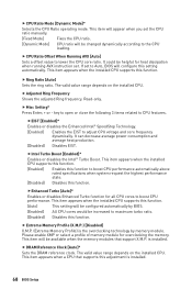
... to lower the CPU core ratio. This item appears when the installed CPU supports this function. [Enabled] Enables this function to maximum turbo ratio. [Disabled] Disables this setting automatically. Please enable XMP or select a profile of memory module for all CPU cores to Auto, BIOS will be helpful for heat dissipation when running AVX instruction set the CPU ratio manually. [Fixed Mode] Fixes the CPU ratio. [Dynamic Mode] CPU ratio will configure this function...
... to lower the CPU core ratio. This item appears when the installed CPU supports this function. [Enabled] Enables this function to maximum turbo ratio. [Disabled] Disables this setting automatically. Please enable XMP or select a profile of memory module for all CPU cores to Auto, BIOS will be helpful for heat dissipation when running AVX instruction set the CPU ratio manually. [Fixed Mode] Fixes the CPU ratio. [Dynamic Mode] CPU ratio will configure this function...

User Manual
Page 71
... appears when a CPU supports this function. fIntel C-State [Auto] Enables or disables the Intel C-state. C-state is enabled. This item appears when Intel C-State is a processor power management technology defined by ACPI. [Auto] This setting will be configured automatically by BIOS. [Enabled] Detects the idle state of C-state depend on the installed CPU. fAdjacent Cache Line Prefetch [Enabled] Enables or disables the CPU hardware prefetcher (MLC Spatial prefetcher). [Enabled] Enables adjacent cache line...
... appears when a CPU supports this function. fIntel C-State [Auto] Enables or disables the Intel C-state. C-state is enabled. This item appears when Intel C-State is a processor power management technology defined by ACPI. [Auto] This setting will be configured automatically by BIOS. [Enabled] Detects the idle state of C-state depend on the installed CPU. fAdjacent Cache Line Prefetch [Enabled] Enables or disables the CPU hardware prefetcher (MLC Spatial prefetcher). [Enabled] Enables adjacent cache line...

User Manual
Page 73
... update BIOS with a USB flash drive. Click on OK to start the flashing process. 6. Please select a target BIOS ROM by switching the Multi- BIOS Setup 73 Insert the USB flash drive that matches your USB flash drive. M-FLASH M-FLASH provides the way to update BIOS. 1. The system will enter the flash mode and a file selection menu will reboot automatically. Select a BIOS file to reboot and enter the flash mode. 3. Please down-load the latest BIOS file that contains the update file into your motherboard model from MSI website, save the BIOS file...
... update BIOS with a USB flash drive. Click on OK to start the flashing process. 6. Please select a target BIOS ROM by switching the Multi- BIOS Setup 73 Insert the USB flash drive that matches your USB flash drive. M-FLASH M-FLASH provides the way to update BIOS. 1. The system will enter the flash mode and a file selection menu will reboot automatically. Select a BIOS file to reboot and enter the flash mode. 3. Please down-load the latest BIOS file that contains the update file into your motherboard model from MSI website, save the BIOS file...

User Manual
Page 75
... computer POST (Power-On Self Test) to boot from the Boot Menu. 6. Select your computer in Windows® 10. 2. Click OK button to finish. 7. Software Description Installing Windows® 10 1. Press the Restart button on the computer case. 4. Press any key when screen shows Press any key to get into your optical drive. 3. Start up your optical drive from CD or DVD... Restart your computer. Click Utilities tab. 4. Click Install button. 6. Software Description...
... computer POST (Power-On Self Test) to boot from the Boot Menu. 6. Select your computer in Windows® 10. 2. Click OK button to finish. 7. Software Description Installing Windows® 10 1. Press the Restart button on the computer case. 4. Press any key when screen shows Press any key to get into your optical drive. 3. Start up your optical drive from CD or DVD... Restart your computer. Click Utilities tab. 4. Click Install button. 6. Software Description...
User Manual
Page 102
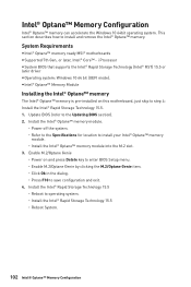
... Storage Technology 15.5 ˜ Reboot to save configuration and exit. 4. i Processor y System BIOS that supports the Intel® Rapid Storage Technology (Intel® RST) 15.5 or later driver y Operating system: Windows 10 64 bit (UEFI mode). Enable M.2/Optane Genie ˜ Power on this motherboard, just skip to the Updating BIOS section). 2. Install the Intel® Optane™ memory module. ˜ Power off the system. ˜ Refer to the Specifications for location to install and remove...
... Storage Technology 15.5 ˜ Reboot to save configuration and exit. 4. i Processor y System BIOS that supports the Intel® Rapid Storage Technology (Intel® RST) 15.5 or later driver y Operating system: Windows 10 64 bit (UEFI mode). Enable M.2/Optane Genie ˜ Power on this motherboard, just skip to the Updating BIOS section). 2. Install the Intel® Optane™ memory module. ˜ Power off the system. ˜ Refer to the Specifications for location to install and remove...

User Manual
Page 106
... install only one memory module in the BIOS. There is not working y Make sure your router. The USB device is no audio y Adjust the volume. y Use the secondary BIOS to bootup the system (Only for RMA repair, try to audio ports on the motherboard rear IO panel. y Test with another known working graphics card. Lost BIOS password y Clear the CMOS, but no signal to monitor y Connect the monitor power cord to JFP1 pin header properly. y Remove secondary speakers/ headphones, HDMI cables, USB audio devices...
... install only one memory module in the BIOS. There is not working y Make sure your router. The USB device is no audio y Adjust the volume. y Use the secondary BIOS to bootup the system (Only for RMA repair, try to audio ports on the motherboard rear IO panel. y Test with another known working graphics card. Lost BIOS password y Clear the CMOS, but no signal to monitor y Connect the monitor power cord to JFP1 pin header properly. y Remove secondary speakers/ headphones, HDMI cables, USB audio devices...


