User Guide
Page 8
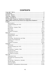
... Safety Instructions iii FCC-B Radio Frequency Interference Statement iv WEEE (Waste Electrical and Electronic Equipment) Statement v English ...En-1 Specifications ...En-2 Central Processing Unit: CPU En-5 Memory ...En-7 Connectors, Jumpers, Slots En-9 Back Panel ...En-18 BIOS Setup ...En-21 Software Information En-25 Deutsch ...De-1 Spezifikationen De-2 Hauptprozessor: CPU De-5 Speicher...
... Safety Instructions iii FCC-B Radio Frequency Interference Statement iv WEEE (Waste Electrical and Electronic Equipment) Statement v English ...En-1 Specifications ...En-2 Central Processing Unit: CPU En-5 Memory ...En-7 Connectors, Jumpers, Slots En-9 Back Panel ...En-18 BIOS Setup ...En-21 Software Information En-25 Deutsch ...De-1 Spezifikationen De-2 Hauptprozessor: CPU De-5 Speicher...
User Guide
Page 10
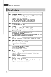
South Bridge: NVIDIA® nForce 430i (MCP51) Memory Support - m s i. fu nc =t es t r ep or t ) LAN - Transfer rate is up to 4 IDE devices SATA - 4 SATAII ports by nForce 430i - 2 eSATA ports by Realtek® ... (8GB Max) (For more information on back panel) - Chip integrated by nForce 430i - Supports up to 300 MB/s En-2 North Bridge: NVIDIA® nForce 750i SLI (C72P) - Up to 400Mbps Audio - Supports Intel® Hyper-Threading (HT) Technology (For the latest information about CPU, please visit ht t p : / / g lobal. p hp ?f un c = c p uf...
South Bridge: NVIDIA® nForce 430i (MCP51) Memory Support - m s i. fu nc =t es t r ep or t ) LAN - Transfer rate is up to 4 IDE devices SATA - 4 SATAII ports by nForce 430i - 2 eSATA ports by Realtek® ... (8GB Max) (For more information on back panel) - Chip integrated by nForce 430i - Supports up to 300 MB/s En-2 North Bridge: NVIDIA® nForce 750i SLI (C72P) - Up to 400Mbps Audio - Supports Intel® Hyper-Threading (HT) Technology (For the latest information about CPU, please visit ht t p : / / g lobal. p hp ?f un c = c p uf...

User Guide
Page 15
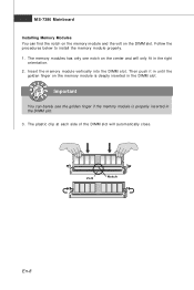
...All DIMM slots are m arked in PINK color. 72x2=144 pin 48x2=96 pin Important - In Dual-Channel mode, make sure that you install memory modules of the same type and density in the DDR3 DIMM slots. - DIMM slot(s) on Channel B are BLUE color. To enable successful system boot...-up, always insert the memory modules into the DIMM1 first. Dual channels definition : DIMM slot(s) on Channel A are marked in BLUE color. Dual channels definition : DIMM slot(s) on ...
...All DIMM slots are m arked in PINK color. 72x2=144 pin 48x2=96 pin Important - In Dual-Channel mode, make sure that you install memory modules of the same type and density in the DDR3 DIMM slots. - DIMM slot(s) on Channel B are BLUE color. To enable successful system boot...-up, always insert the memory modules into the DIMM1 first. Dual channels definition : DIMM slot(s) on Channel A are marked in BLUE color. Dual channels definition : DIMM slot(s) on ...
User Guide
Page 16
... each side of the DIMM slot will only fit in the right ori ent at i on the memory module is properly inserted in the DIMM slot. 3. Important You can find the notch on the memory module and the volt on the DIMM slot. Volt Notch En-8 Insert the m em ory module vertically... slot. Follow the procedures below to install the m em ory m odule properly. 1. Then push it in until the golden finger on . 2. MS-7380 Mainboard Installing Memory Modules You can barely see the golden finger if the...
... each side of the DIMM slot will only fit in the right ori ent at i on the memory module is properly inserted in the DIMM slot. 3. Important You can find the notch on the memory module and the volt on the DIMM slot. Volt Notch En-8 Insert the m em ory module vertically... slot. Follow the procedures below to install the m em ory m odule properly. 1. Then push it in until the golden finger on . 2. MS-7380 Mainboard Installing Memory Modules You can barely see the golden finger if the...
User Guide
Page 22
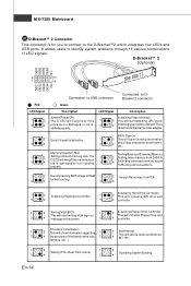
... 2 3 4 Connected to USB connector Connected to identify system problems through 16 various combinations of LED signals. Memory Detection Test Testing Base and Extended Memory 1 2 Testing onboard memory size. Initializing Video Interface 2 This will start showing information 3 4 about logo, processor brand name, etc......processor (like brand name, sys- 3 4 INT 19h. The 1 2 Testing base memory from 240K to 3 D-LED will hang if the memory mod4 ule is damaged or not installed 3 4 640K and extended memory above 1MB using various patterns. tem bus, etc...) 1 2 1 2 Testing RTC (...
... 2 3 4 Connected to USB connector Connected to identify system problems through 16 various combinations of LED signals. Memory Detection Test Testing Base and Extended Memory 1 2 Testing onboard memory size. Initializing Video Interface 2 This will start showing information 3 4 about logo, processor brand name, etc......processor (like brand name, sys- 3 4 INT 19h. The 1 2 Testing base memory from 240K to 3 D-LED will hang if the memory mod4 ule is damaged or not installed 3 4 640K and extended memory above 1MB using various patterns. tem bus, etc...) 1 2 1 2 Testing RTC (...
User Guide
Page 29
... for optimum use. English BIOS Setup This chapter provides basic information on the screen during the system booting up , the 1st line appearing after the memory count is usually in this BIOS was released.
... for optimum use. English BIOS Setup This chapter provides basic information on the screen during the system booting up , the 1st line appearing after the memory count is usually in this BIOS was released.


