
User Guide
Page 2
...user's manual, please contact your place of Microsoft Corporation. AMI® is given as to make changes without notice. W indows® 95/98/2000/NT/XP are registered trademarks of purchase or local distributor. Revision History Revision V1.0 Revision History First release for Europe Date January 2008 Technical Support If a problem... following help resources for FAQ, technical guide, BIOS updates, driver updates, and other countries. Visit the MSI website for further guidance. func=faqIndex Contact our technical staff at: http://support.msi.com.tw/ ii NVIDIA, the NVIDIA...
...user's manual, please contact your place of Microsoft Corporation. AMI® is given as to make changes without notice. W indows® 95/98/2000/NT/XP are registered trademarks of purchase or local distributor. Revision History Revision V1.0 Revision History First release for Europe Date January 2008 Technical Support If a problem... following help resources for FAQ, technical guide, BIOS updates, driver updates, and other countries. Visit the MSI website for further guidance. func=faqIndex Contact our technical staff at: http://support.msi.com.tw/ ii NVIDIA, the NVIDIA...
User Guide
Page 3
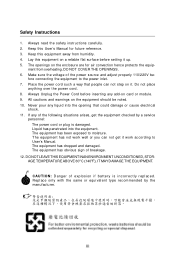
... Unplug the Power Cord before setting it . Always read the safety instructions carefully. 2. Make sure the voltage of expl os i on card or module. 9. If any liquid into the equipment. † The equipment has been exposed to the power inlet. 7. Replac e only with the same or equivalent type rec ommended by a service personnel: † The power cord or plug is damaged...
... Unplug the Power Cord before setting it . Always read the safety instructions carefully. 2. Make sure the voltage of expl os i on card or module. 9. If any liquid into the equipment. † The equipment has been exposed to the power inlet. 7. Replac e only with the same or equivalent type rec ommended by a service personnel: † The power cord or plug is damaged...
User Guide
Page 8
... Tradema rks ...ii Revision History ...ii Technical Support ...ii Safety Instructions iii FCC-B Radio Frequency Interference Statement iv WEEE (Waste Electrical and Electronic Equipment) Statement v English ...En-1 Specifications ...En-2 Central Processing Unit: CPU En-5 Memory ...En-7 Connectors, Jumpers, Slots En-9 Back Panel ...En-18 BIOS Setup ...En-21 Software Information En-25 Deutsch ...De-1 Spezifikationen De-2 Hauptprozessor: CPU De-5 Speicher ...De-7 Anschlüsse...
... Tradema rks ...ii Revision History ...ii Technical Support ...ii Safety Instructions iii FCC-B Radio Frequency Interference Statement iv WEEE (Waste Electrical and Electronic Equipment) Statement v English ...En-1 Specifications ...En-2 Central Processing Unit: CPU En-5 Memory ...En-7 Connectors, Jumpers, Slots En-9 Back Panel ...En-18 BIOS Setup ...En-21 Software Information En-25 Deutsch ...De-1 Spezifikationen De-2 Hauptprozessor: CPU De-5 Speicher ...De-7 Anschlüsse...
User Guide
Page 10
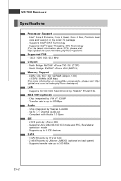
...-7380 Mainboard Specifications Processor Support - c om . m s i. ph p? fu nc =t es t r ep or t ) LAN - Chip integrated by Realtek® RTL8211BL IEEE 1394 (optional) - Supports up to 400Mbps Audio - Supports Intel® Hyper-Threading (HT) Technology (For the latest information about CPU, please visit ht t p : / / g lobal. t w / i nd ex. North Bridge: NVIDIA® nForce 750i SLI (C72P) - Supports Ultra DMA 66/100/133 mode and PIO, Bus Master operation mode - Supports...
...-7380 Mainboard Specifications Processor Support - c om . m s i. ph p? fu nc =t es t r ep or t ) LAN - Chip integrated by Realtek® RTL8211BL IEEE 1394 (optional) - Supports up to 400Mbps Audio - Supports Intel® Hyper-Threading (HT) Technology (For the latest information about CPU, please visit ht t p : / / g lobal. t w / i nd ex. North Bridge: NVIDIA® nForce 750i SLI (C72P) - Supports Ultra DMA 66/100/133 mode and PIO, Bus Master operation mode - Supports...
User Guide
Page 11
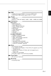
... port - 2 eSATA ports - 1 Clear CMOS button - 4 USB 2.0 ports - 1 LAN jack - 6 flexible audio jacks On-Board Pinheaders - 1 Chassis Intrusion pinheader - 2 USB 2.0 pinheaders - 1 IEEE 1394 pinheader (optional) - 1 SPDIF-out pinheader - 1 CD-in connector - 1 front panel audio pinheader - 1 TPM Module pinheader (optional) - 1 COM Port pinheader (optional) Slots - 3 PCI Express x16 slots a. English RAID - 4 SATA ports support RAID 0/ 1/ 0+1/ 5 or JBOD mode - 2 eSATA ports (back panel) support RAID 0/ 1 mode Floppy - 1 floppy port - supports SLI technology - 2 PCI slots, support 3.3V/ 5V PCI bus...
... port - 2 eSATA ports - 1 Clear CMOS button - 4 USB 2.0 ports - 1 LAN jack - 6 flexible audio jacks On-Board Pinheaders - 1 Chassis Intrusion pinheader - 2 USB 2.0 pinheaders - 1 IEEE 1394 pinheader (optional) - 1 SPDIF-out pinheader - 1 CD-in connector - 1 front panel audio pinheader - 1 TPM Module pinheader (optional) - 1 COM Port pinheader (optional) Slots - 3 PCI Express x16 slots a. English RAID - 4 SATA ports support RAID 0/ 1/ 0+1/ 5 or JBOD mode - 2 eSATA ports (back panel) support RAID 0/ 1 mode Floppy - 1 floppy port - supports SLI technology - 2 PCI slots, support 3.3V/ 5V PCI bus...

User Guide
Page 13
... or beyond product specifications is designed to tolerate such abnormal setting, while doing overclocking. Any attempt to enhance heat dissipation. If you apply an even layer of CPU. Replacing the CPU While replacing the CPU, always turn off the ATX power supply or unplug the power supply's power cord from overheating. However, please make sure the cooling fan can work properly to protect the CPU from the grounded...
... or beyond product specifications is designed to tolerate such abnormal setting, while doing overclocking. Any attempt to enhance heat dissipation. If you apply an even layer of CPU. Replacing the CPU While replacing the CPU, always turn off the ATX power supply or unplug the power supply's power cord from overheating. However, please make sure the cooling fan can work properly to protect the CPU from the grounded...
User Guide
Page 17
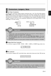
...connector supports 360KB, 720KB, 1.2MB, 1.44MB or 2.88MB floppy disk drive. 6 IDE connector This connector supports IDE hard disk drives, optical disk drives and other IDE devices. Refer to the connectors, always take advantage of the fan control. English Connectors, Jumpers, Slots 4 Fan Power Connectors The fan power connectors support system cooling fan with 3 or 4 pins power connector are both available for proper CPU cooling fan. 2. When connect the wire to IDE device's documentation supplied by setting jumpers. CPUFAN supports fan control. The CPU FAN supports Smart FAN...
...connector supports 360KB, 720KB, 1.2MB, 1.44MB or 2.88MB floppy disk drive. 6 IDE connector This connector supports IDE hard disk drives, optical disk drives and other IDE devices. Refer to the connectors, always take advantage of the fan control. English Connectors, Jumpers, Slots 4 Fan Power Connectors The fan power connectors support system cooling fan with 3 or 4 pins power connector are both available for proper CPU cooling fan. 2. When connect the wire to IDE device's documentation supplied by setting jumpers. CPUFAN supports fan control. The CPU FAN supports Smart FAN...

User Guide
Page 18
The JFP1 is a high-speed Serial ATA interface port. Power Switch Power LED 10 9 21 JFP1 Reset Switch HDD LED 87 Speaker Power LED 21 JFP2 9 IEEE1394 Connector (Green) This connector allows you to one Serial ATA device. En-10 Each connector can connect to connect the IEEE1394 device via an optional IEEE1394 brac ket . Otherwise, data loss may occur during transmission. 8 Front Panel Connectors These connectors are for electrical connection to the front panel switches and LEDs. Important Please do not...
The JFP1 is a high-speed Serial ATA interface port. Power Switch Power LED 10 9 21 JFP1 Reset Switch HDD LED 87 Speaker Power LED 21 JFP2 9 IEEE1394 Connector (Green) This connector allows you to one Serial ATA device. En-10 Each connector can connect to connect the IEEE1394 device via an optional IEEE1394 brac ket . Otherwise, data loss may occur during transmission. 8 Front Panel Connectors These connectors are for electrical connection to the front panel switches and LEDs. Important Please do not...
User Guide
Page 19
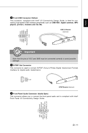
... Key (no pin) Important Note that the pins of VCC and GND must be connected correctly to connect S/PDIF (Sony & Philips Digital Interconnect Format) interface for connecting high-speed USB interface peripherals such as USB HDD, digital cameras, MP3 players, printers, modems and the like. VCC SPDIF_out GND SPDIF Bracket (Optional) 12 Front Panel Audio Connector (Azalia Spec) This connector allows you to connect the front panel audio and is used to...
... Key (no pin) Important Note that the pins of VCC and GND must be connected correctly to connect S/PDIF (Sony & Philips Digital Interconnect Format) interface for connecting high-speed USB interface peripherals such as USB HDD, digital cameras, MP3 players, printers, modems and the like. VCC SPDIF_out GND SPDIF Bracket (Optional) 12 Front Panel Audio Connector (Azalia Spec) This connector allows you to connect the front panel audio and is used to...
User Guide
Page 20
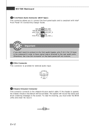
... must enter the BIOS utility and clear the record. 1 CINTRU GND En-12 MS-7380 Mainboard 13 Front Panel Audio Connector (AC97 Spec) This connector allows you to connect the front panel audio and is provided for external audio input. Otherwise, the Line-Out connector on the screen. To clear the warning, you don't want to connect to the front audio header, pins 5 & 6, 9 & 10 have signal output directed to the chassis intrusion switch cable...
... must enter the BIOS utility and clear the record. 1 CINTRU GND En-12 MS-7380 Mainboard 13 Front Panel Audio Connector (AC97 Spec) This connector allows you to connect the front panel audio and is provided for external audio input. Otherwise, the Line-Out connector on the screen. To clear the warning, you don't want to connect to the front audio header, pins 5 & 6, 9 & 10 have signal output directed to the chassis intrusion switch cable...

User Guide
Page 21
... Yout Ground (5) Cout 3 19 VoIP Card Connector This connector connects to the VoIP card. You must configure the setting through the BIOS setup to use the infrared function. 12 NC NC VCC5 Ground IRTX IRRX 56 17 Serial Port Connector This connector is compliant with Intel® Front Panel I/O Connectivity Design Guide. English 16 Infrared Module Connector This connector allows you to attach an optional TV-Out bracket that sends...
... Yout Ground (5) Cout 3 19 VoIP Card Connector This connector connects to the VoIP card. You must configure the setting through the BIOS setup to use the infrared function. 12 NC NC VCC5 Ground IRTX IRRX 56 17 Serial Port Connector This connector is compliant with Intel® Front Panel I/O Connectivity Design Guide. English 16 Infrared Module Connector This connector allows you to attach an optional TV-Out bracket that sends...
User Guide
Page 22
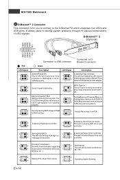
...memory above 1MB using various patterns. Memory Detection Test Testing Base and Extended Memory 1 2 Testing onboard memory size. The 1 2 Testing base memory from 240K to the D-Bracket™2 which integrates four LEDs and USB ports. properly. 1 2 Decompressing BIOS image to RAM 1 2 Assign Resources to all ISA. 3 4 for fast booting. 3 4 1 2 Initializing Keyboard Controller. 1 2 Initializing Hard Drive Controller This will initialize IDE drive and 3 4 3 4 controller. 1 2 Testing VGA BIOS 1 2 Initializing Floppy Drive Controller This will start writing VGA...
...memory above 1MB using various patterns. Memory Detection Test Testing Base and Extended Memory 1 2 Testing onboard memory size. The 1 2 Testing base memory from 240K to the D-Bracket™2 which integrates four LEDs and USB ports. properly. 1 2 Decompressing BIOS image to RAM 1 2 Assign Resources to all ISA. 3 4 for fast booting. 3 4 1 2 Initializing Keyboard Controller. 1 2 Initializing Hard Drive Controller This will initialize IDE drive and 3 4 3 4 controller. 1 2 Testing VGA BIOS 1 2 Initializing Floppy Drive Controller This will start writing VGA...
User Guide
Page 23
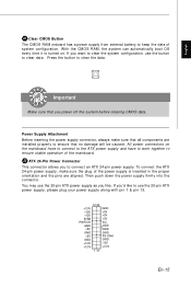
... components are aligned. Power Supply Attachment Before inserting the power supply connector, always make sure the plug of system configuration. Then push down the power supply firmly into the c on . Press the button to use the button to keep the data of the power supply is turned on nec t or . If you want to clear the system configuration, use the 20-pin ATX power supply, please plug your power supply along with pin 1 & pin 13. 12 24...
... components are aligned. Power Supply Attachment Before inserting the power supply connector, always make sure the plug of system configuration. Then push down the power supply firmly into the c on . Press the button to use the button to keep the data of the power supply is turned on nec t or . If you want to clear the system configuration, use the 20-pin ATX power supply, please plug your power supply along with pin 1 & pin 13. 12 24...
User Guide
Page 24
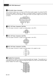
... 25 ATX 12V Power Connector (2x4-Pin) This 12V power connector is used to provide power to the CPU. +12V 8 5 4 1 GND 26 ATX 12V Power Connector (1x4-Pin) This 12V power connector is used to connect an optional parallel port bracket. MS-7380 Mainboard 23 ATX 20-Pin Power Connector This connector allows you to the graphics card. 1 5V 2 GND 3 GND 4 12V 27 Parallel Port Connector This connector is a standard printer port that supports Enhanced Parallel Port (EPP) and Extended Capa- Key(No pin) SLCT...
... 25 ATX 12V Power Connector (2x4-Pin) This 12V power connector is used to provide power to the CPU. +12V 8 5 4 1 GND 26 ATX 12V Power Connector (1x4-Pin) This 12V power connector is used to connect an optional parallel port bracket. MS-7380 Mainboard 23 ATX 20-Pin Power Connector This connector allows you to the graphics card. 1 5V 2 GND 3 GND 4 12V 27 Parallel Port Connector This connector is a standard printer port that supports Enhanced Parallel Port (EPP) and Extended Capa- Key(No pin) SLCT...

User Guide
Page 25
... Module) module (optional). PCI Express x 16 Slot PCI Express x 4 Slot PCI Express x 1 Slot 29 PCI (Peripheral Component Interconnect) Slot The PCI slot supports LAN card, SCSI card, USB card, and other add-on cards that you unplug the power supply first. Please refer to the TPM security platform manual for the expansion card, such as jumpers, switches or BIOS configuration. 30 TPM Module Connector This connector connects to configure any necessary hardware or software settings for more details and usages. GND GND Key(no pin) VCC5 SIRQ...
... Module) module (optional). PCI Express x 16 Slot PCI Express x 4 Slot PCI Express x 1 Slot 29 PCI (Peripheral Component Interconnect) Slot The PCI slot supports LAN card, SCSI card, USB card, and other add-on cards that you unplug the power supply first. Please refer to the TPM security platform manual for the expansion card, such as jumpers, switches or BIOS configuration. 30 TPM Module Connector This connector connects to configure any necessary hardware or software settings for more details and usages. GND GND Key(no pin) VCC5 SIRQ...
User Guide
Page 27
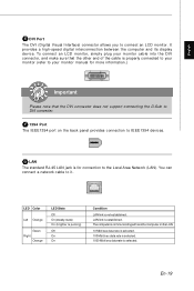
... display devic e. LAN link is selected. F 1394 Port The IEEE1394 port on the back panel provides connection to the Local Area Network (LAN). You can connect a network cable to connect an LCD monitor. En-19 LED Color Left Orange Green Right Orange LED State Off On (steady state) On (brighter & pulsing) Off On On Condition LAN link is properly connected to your monitor (refer to your monitor manual for connection to IEEE1394 devices...
... display devic e. LAN link is selected. F 1394 Port The IEEE1394 port on the back panel provides connection to the Local Area Network (LAN). You can connect a network cable to connect an LCD monitor. En-19 LED Color Left Orange Green Right Orange LED State Off On (steady state) On (brighter & pulsing) Off On On Condition LAN link is properly connected to your monitor (refer to your monitor manual for connection to IEEE1394 devices...
User Guide
Page 29
... , and requests you to configure the system for optimum use. It is the BIOS version. En-21 English BIOS Setup This chapter provides basic information on the BIOS Setup program and allows you to run the Setup program when: * An error message appears on the screen during the system booting up , the 1st line appearing after the memory count is usually in this...
... , and requests you to configure the system for optimum use. It is the BIOS version. En-21 English BIOS Setup This chapter provides basic information on the BIOS Setup program and allows you to run the Setup program when: * An error message appears on the screen during the system booting up , the 1st line appearing after the memory count is usually in this...
User Guide
Page 30
... MS-7380 Mainboard Entering Setup Power on -line description of the highlighted setup function is the Main Menu. Getting Help After entering the Setup m enu, the first menu you can use control keys (↑↓ ) to highlight the field and press to the main menu, just press . Then you will start POST (Power On Self Test) process. If you still wish to enter Setup, restart the system by turning it OFF...
... MS-7380 Mainboard Entering Setup Power on -line description of the highlighted setup function is the Main Menu. Getting Help After entering the Setup m enu, the first menu you can use control keys (↑↓ ) to highlight the field and press to the main menu, just press . Then you will start POST (Power On Self Test) process. If you still wish to enter Setup, restart the system by turning it OFF...

User Guide
Page 31
... frequency/voltage control and overclocking. Load Fail-Safe Defaults Use this menu to load the default values set by the mainboard manufacturer specifically for integrated peripherals. Standard CMOS Features Use this menu to specify your settings for optim al perform ance of special enhanced features. Integrated Peripherals Use this menu for power management. Power Management Setup Use this menu to save/ load your settings for basic system configurations, such as time, date etc. Load Optimized Defaults Use this menu to set by the BIOS...
... frequency/voltage control and overclocking. Load Fail-Safe Defaults Use this menu to load the default values set by the mainboard manufacturer specifically for integrated peripherals. Standard CMOS Features Use this menu to specify your settings for optim al perform ance of special enhanced features. Integrated Peripherals Use this menu for power management. Power Management Setup Use this menu to save/ load your settings for basic system configurations, such as time, date etc. Load Optimized Defaults Use this menu to set by the BIOS...

User Guide
Page 33
... the MSI website to activate the device. The Driver/Utility CD contains the: Driver menu - Install the driver by your desire and to get the latest drivers and BIOS for better system performance. The Utility menu shows the software applications that is included in the mainboard package, and place it into the CD-ROM driver. English Software Information Take out the Driver/Utility CD that the mainboard supports. The installation will auto-run...
... the MSI website to activate the device. The Driver/Utility CD contains the: Driver menu - Install the driver by your desire and to get the latest drivers and BIOS for better system performance. The Utility menu shows the software applications that is included in the mainboard package, and place it into the CD-ROM driver. English Software Information Take out the Driver/Utility CD that the mainboard supports. The installation will auto-run...


