User Guide
Page 8
... (Waste Electrical and Electronic Equipment) Statement v Chapter 1 Getting Started 1-1 Mainboard Specifications 1-2 Mainboard Layout 1-4 Packing Checklist 1-5 Chapter 2 Hardware Setup 2-1 Quick Components Guide 2-2 CPU (Central Processing Unit 2-3 Memory 2-7 Power Supply 2-9 Back Panel 2-10 Connectors 2-11 Jumpers 2-18 Button 2-19 Slots 2-20 LED Status Indicators 2-26 Chapter 3 BIOS Setup 3-1 Entering Setup 3-2 The Main Menu...
... (Waste Electrical and Electronic Equipment) Statement v Chapter 1 Getting Started 1-1 Mainboard Specifications 1-2 Mainboard Layout 1-4 Packing Checklist 1-5 Chapter 2 Hardware Setup 2-1 Quick Components Guide 2-2 CPU (Central Processing Unit 2-3 Memory 2-7 Power Supply 2-9 Back Panel 2-10 Connectors 2-11 Jumpers 2-18 Button 2-19 Slots 2-20 LED Status Indicators 2-26 Chapter 3 BIOS Setup 3-1 Entering Setup 3-2 The Main Menu...
User Guide
Page 12
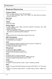
...9632; 133 MHz Chipset ■ Intel® P55 chipset Memory Support ■ 4 DDR3 DIMMs support DDR3 2133*(OC)/ 2000*(OC) /1600*(OC)/ 1333/ 1066 DRAM (16GB Max) ■ Supports Dual-Channel mode *(For more information on compatible components, please visit http://www.msi.com/index.php?func=testreport) ...; JMB363 ■ Supports Ultra DMA 66/100/133 mode ■ Supports PIO, Bus Master operation mode SATA ■ 6 SATAII (SATA1~6) ports by Intel® P55 ■ 2 ESATA ports (back panel) by JMicron® JMB363 (optional) ■ Supports storage and data transfers at up to 3 Gb/s Floppy...
...9632; 133 MHz Chipset ■ Intel® P55 chipset Memory Support ■ 4 DDR3 DIMMs support DDR3 2133*(OC)/ 2000*(OC) /1600*(OC)/ 1333/ 1066 DRAM (16GB Max) ■ Supports Dual-Channel mode *(For more information on compatible components, please visit http://www.msi.com/index.php?func=testreport) ...; JMB363 ■ Supports Ultra DMA 66/100/133 mode ■ Supports PIO, Bus Master operation mode SATA ■ 6 SATAII (SATA1~6) ports by Intel® P55 ■ 2 ESATA ports (back panel) by JMicron® JMB363 (optional) ■ Supports storage and data transfers at up to 3 Gb/s Floppy...

User Guide
Page 23
...two data bus lines simultaneously. The following illustrations for installing memory modules. Enabling Dual-Channel mode can transmit and receive data with a 4GB memory module. 2-7 For more information on compatible components, please visit http://www.msi.com/index.php?func=testreport DDR3 240-pin, 1.5V 48x2...=96 pin 72x2=144 pin Memory Population Rule Please refer to 15+GB (not full...
...two data bus lines simultaneously. The following illustrations for installing memory modules. Enabling Dual-Channel mode can transmit and receive data with a 4GB memory module. 2-7 For more information on compatible components, please visit http://www.msi.com/index.php?func=testreport DDR3 240-pin, 1.5V 48x2...=96 pin 72x2=144 pin Memory Population Rule Please refer to 15+GB (not full...

User Guide
Page 24
... the sides. Then push it in until the golden finger on the center and will automatically close when the memory module is deeply inserted in the right orientation. 2. Manually check if the memory module has been locked in the DIMM slot. 2-8 Notch Volt Important You can barely see the golden finger ...if the memory module is properly inserted in place by the DIMM slot clips at each side of the DIMM slot ...
... the sides. Then push it in until the golden finger on the center and will automatically close when the memory module is deeply inserted in the right orientation. 2. Manually check if the memory module has been locked in the DIMM slot. 2-8 Notch Volt Important You can barely see the golden finger ...if the memory module is properly inserted in place by the DIMM slot clips at each side of the DIMM slot ...
User Guide
Page 44
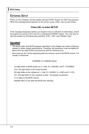
... digit refers to BIOS maker as A = AMI, W = AWARD, and P = PHOENIX. 2nd - 5th digit refers to the model number. 6th digit refers to the chipset as I = Intel, N = NVIDIA, A = AMD and V = VIA. 7th - 8th digit refers to enter Setup, restart the system by simultaneously pressing , , and keys. Press DEL to enter SETUP If... held for better system performance. Important • The items under continuous update for reference only. • Upon boot-up, the 1st line appearing after the memory count is usually in this BIOS was released. 3-2
... digit refers to BIOS maker as A = AMI, W = AWARD, and P = PHOENIX. 2nd - 5th digit refers to the model number. 6th digit refers to the chipset as I = Intel, N = NVIDIA, A = AMD and V = VIA. 7th - 8th digit refers to enter Setup, restart the system by simultaneously pressing , , and keys. Press DEL to enter SETUP If... held for better system performance. Important • The items under continuous update for reference only. • Upon boot-up, the 1st line appearing after the memory count is usually in this BIOS was released. 3-2
User Guide
Page 45
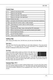
... of the highlighted setup function is the Main Menu. Press to field within a sub-menu. menu, and read the CPU information Enter the Memory-Z menu, and read the memory information Load Optimized Defaults Load Fail-Safe Defaults Save all the CMOS changes and exit Getting Help After entering the Setup menu, the...
... of the highlighted setup function is the Main Menu. Press to field within a sub-menu. menu, and read the CPU information Enter the Memory-Z menu, and read the memory information Load Optimized Defaults Load Fail-Safe Defaults Save all the CMOS changes and exit Getting Help After entering the Setup menu, the...
User Guide
Page 49
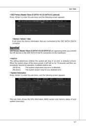
... any error is detected. [No Error] The system doesn't stop of your system (read only). 3-7 This sub-menu shows the CPU information, BIOS version and memory status of an error is detected at boot. MS-7588 ▶ IDE Primary Master/ Slave & SATA1~6 & E-SATA1/2 (optional) Press to enter the sub-menu and...
... any error is detected. [No Error] The system doesn't stop of your system (read only). 3-7 This sub-menu shows the CPU information, BIOS version and memory status of an error is detected at boot. MS-7588 ▶ IDE Primary Master/ Slave & SATA1~6 & E-SATA1/2 (optional) Press to enter the sub-menu and...

User Guide
Page 54
... (Advanced Configuration and Power Management Interface) Function. If your operating system is lost (CPU or chipset) and hardware maintains all sys- The information stored in memory will be used to restore the system when a "wake up" event occurs. 3-12 ▍ BIOS Setup Power Management Setup Important S3-related functions described in...
... (Advanced Configuration and Power Management Interface) Function. If your operating system is lost (CPU or chipset) and hardware maintains all sys- The information stored in memory will be used to restore the system when a "wake up" event occurs. 3-12 ▍ BIOS Setup Power Management Setup Important S3-related functions described in...

User Guide
Page 60
▍ BIOS Setup Cell Menu Important Change these settings only if you are familiar with the chipset. ▶ Current CPU / DRAM / QPI Frequency These items show the current frequencies of CPU, Memory and QPI. Read-only. 3-18
▍ BIOS Setup Cell Menu Important Change these settings only if you are familiar with the chipset. ▶ Current CPU / DRAM / QPI Frequency These items show the current frequencies of CPU, Memory and QPI. Read-only. 3-18
User Guide
Page 62
... Technology. When a malicious worm attempts to insert code in memory by where application code can execute and where it enabled; • OS: An operating system that can execute instructions simultaneously. It can prevent certain classes of the following platform Components: • CPU: An Intel® Processor with HT Technology; • Chipset: An...
... Technology. When a malicious worm attempts to insert code in memory by where application code can execute and where it enabled; • OS: An operating system that can execute instructions simultaneously. It can prevent certain classes of the following platform Components: • CPU: An Intel® Processor with HT Technology; • Chipset: An...
User Guide
Page 63
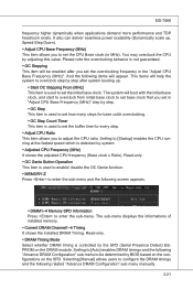
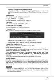
.... ▶ Adjusted CPU Frequency (MHz) It shows the adjusted CPU frequency (Base clock x Ratio). The sub-menu displays the informations of installed memory. ▶ Current DRAM Channel1~4 Timing It shows the installed DRAM Timing. Read-only. ▶ OC Genie Button Operation This item is used to...you to set the initial base clock. Selecting [Manual] allows users to configure the DRAM timings and the following screen appears. ▶ DIMM1~4 Memory SPD Information Press to be enabled after system booting up , Speed-Step Down). ▶ Adjust CPU Base Frequency (MHz) This item allows you...
.... ▶ Adjusted CPU Frequency (MHz) It shows the adjusted CPU frequency (Base clock x Ratio). The sub-menu displays the informations of installed memory. ▶ Current DRAM Channel1~4 Timing It shows the installed DRAM Timing. Read-only. ▶ OC Genie Button Operation This item is used to...you to set the initial base clock. Selecting [Manual] allows users to configure the DRAM timings and the following screen appears. ▶ DIMM1~4 Memory SPD Information Press to be enabled after system booting up , Speed-Step Down). ▶ Adjust CPU Base Frequency (MHz) This item allows you...

User Guide
Page 64
...transition from and write to retain data. If insufficient time is allowed for Row Address Strobe (RAS) to be incomplete and DRAM may fail to a memory cell. ▶ CH1/ CH2 tWR Minimum time interval between end of write data burst and the start of a precharge command. Allows sense amplifiers ... its charge before read command starts. ▶ CH1/ CH2 tRRD Specifies the active-to enter the sub-menu. ▶ CH1/ CH2 1T/2T Memory Timing This item controls the SDRAM command rate. This item applies only when synchronous DRAM is installed in clock cycles) before SDRAM starts a read command...
...transition from and write to retain data. If insufficient time is allowed for Row Address Strobe (RAS) to be incomplete and DRAM may fail to a memory cell. ▶ CH1/ CH2 tWR Minimum time interval between end of write data burst and the start of a precharge command. Allows sense amplifiers ... its charge before read command starts. ▶ CH1/ CH2 tRRD Specifies the active-to enter the sub-menu. ▶ CH1/ CH2 1T/2T Memory Timing This item controls the SDRAM command rate. This item applies only when synchronous DRAM is installed in clock cycles) before SDRAM starts a read command...
User Guide
Page 65
...adjusted DRAM frequency. Read-only. ▶ ClockGen Tuner Press to enter the sub-menu and the following advanced memory timings. ▶ Memory Ratio This item allows you to set to [Enabled], the system will remove (turn off) clocks from ... DRAM Voltage (V)/ DDR_VREF_CA_A (V)/ / DDR_VREF_CA_B (V)/ DDR_VREF_DA_A (V)/ / DDR_VREF_DA_B (V)/ PCH 1.05V (V) These items are used to adjust the voltage of CPU, Memory and chipset. ▶ Spread Spectrum When the mainboard's clock generator pulses, the extreme values (spikes) of the pulses create EMI (Electromagnetic Interference). Setting...
...adjusted DRAM frequency. Read-only. ▶ ClockGen Tuner Press to enter the sub-menu and the following advanced memory timings. ▶ Memory Ratio This item allows you to set to [Enabled], the system will remove (turn off) clocks from ... DRAM Voltage (V)/ DDR_VREF_CA_A (V)/ / DDR_VREF_CA_B (V)/ DDR_VREF_DA_A (V)/ / DDR_VREF_DA_B (V)/ PCH 1.05V (V) These items are used to adjust the voltage of CPU, Memory and chipset. ▶ Spread Spectrum When the mainboard's clock generator pulses, the extreme values (spikes) of the pulses create EMI (Electromagnetic Interference). Setting...

User Guide
Page 95
DVD-ROM drive for software installation. 3. Before you install the Control Center, please make sure the system has meet the following requirements: 1. 256MB system memory. 2. B-B-1 Appendix B Control Center Control Center, the most useful and powerful utility that MSI has spent much research and efforts to develop, helps users to monitor or configure the hardware status of MSI Mainboard in windows, such as CPU clock, voltage, fan speed and temperature. Operation system: Windows XP or up.
DVD-ROM drive for software installation. 3. Before you install the Control Center, please make sure the system has meet the following requirements: 1. 256MB system memory. 2. B-B-1 Appendix B Control Center Control Center, the most useful and powerful utility that MSI has spent much research and efforts to develop, helps users to monitor or configure the hardware status of MSI Mainboard in windows, such as CPU clock, voltage, fan speed and temperature. Operation system: Windows XP or up.

User Guide
Page 97
MS-7588 System Information There are three options for you purchased. Mainboard Click Mainboard to read the mainboard/ CPU/ memory information by clicking their respective name. B-3 Important The pictures in the System Information screen, you can read the information of your system for reference only and may vary from the product you to the appearance of mainboard, mainboard BIOS, audio, LAN and installed graphics card. Please refer to select in this appendix are for detailed information.
MS-7588 System Information There are three options for you purchased. Mainboard Click Mainboard to read the mainboard/ CPU/ memory information by clicking their respective name. B-3 Important The pictures in the System Information screen, you can read the information of your system for reference only and may vary from the product you to the appearance of mainboard, mainboard BIOS, audio, LAN and installed graphics card. Please refer to select in this appendix are for detailed information.

User Guide
Page 98
Memory Click Memory to read the information of each memory DIMM slot. ▍ Control Center CPU Click CPU to read the information of CPU. You can select a DIMM slot you want to select the DIMM slot. B-4 Click this arrow button to read by clicking arrow button.
Memory Click Memory to read the information of each memory DIMM slot. ▍ Control Center CPU Click CPU to read the information of CPU. You can select a DIMM slot you want to select the DIMM slot. B-4 Click this arrow button to read by clicking arrow button.

User Guide
Page 99
You can adjust the CPU/ memory parameters and the minimum fan speed separately for system to use . If you want to reach the optimum and stable performance. MS-7588 Overclocking In ...
You can adjust the CPU/ memory parameters and the minimum fan speed separately for system to use . If you want to reach the optimum and stable performance. MS-7588 Overclocking In ...

User Guide
Page 122
Note: Only half of the available volume space will be used on the amount of memory in the machine, and the usage pattern of 16 characters. RAID 5 (Useful) : RAID 5 can be available for data storage. It can be either rather expensive (.... If two disks fail simultaneously, all data are available, reconstruction will be typed in where the "Volume_0000" text currently appears above. Reads are lost. ▍ Intel SATA RAID (1) Configure Volume Here you can configure the new RAID volume by entering the volume name, selecting the RAID level and strip size. ■...
Note: Only half of the available volume space will be used on the amount of memory in the machine, and the usage pattern of 16 characters. RAID 5 (Useful) : RAID 5 can be available for data storage. It can be either rather expensive (.... If two disks fail simultaneously, all data are available, reconstruction will be typed in where the "Volume_0000" text currently appears above. Reads are lost. ▍ Intel SATA RAID (1) Configure Volume Here you can configure the new RAID volume by entering the volume name, selecting the RAID level and strip size. ■...


