
User Guide
Page 4
... that to which can radiate radio frequency energy and, if not installed and used in order to comply with the emission limits. Micro-Star International MS-7338 This device complies with Part 15 of the FCC Rules. Notice 1 The changes or modifications not expressly approved by one or more of the measures...
... that to which can radiate radio frequency energy and, if not installed and used in order to comply with the emission limits. Micro-Star International MS-7338 This device complies with Part 15 of the FCC Rules. Notice 1 The changes or modifications not expressly approved by one or more of the measures...
User Guide
Page 10
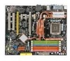
Getting Started Chapter 1 Getting Started Thank you for optimal system efficiency. The P35 Platinum Combo Series mainboards are based on Intel® P35 & ICH9R chipsets for choosing the P35 Platinum Combo Series (MS-7338 v1.X) ATX mainboard. Designed to fit the advanced Intel® Core 2 Quad/Core 2 Duo/ Pentium/Celeron LGA775 processor, the P35 Platinum Combo Series deliver a high performance and professional desktop platform solution. 1-1
Getting Started Chapter 1 Getting Started Thank you for optimal system efficiency. The P35 Platinum Combo Series mainboards are based on Intel® P35 & ICH9R chipsets for choosing the P35 Platinum Combo Series (MS-7338 v1.X) ATX mainboard. Designed to fit the advanced Intel® Core 2 Quad/Core 2 Duo/ Pentium/Celeron LGA775 processor, the P35 Platinum Combo Series deliver a high performance and professional desktop platform solution. 1-1
User Guide
Page 11
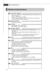
MS-7338 Mainboard Mainboard Specifications Processor Support - m si. Supports VoIP Card (only for ALC888T) IDE - 1 IDE port by VIA VT6308 1-2 Supports 1394 by Marvell 88SE6111 - Intel® ... Azalia 1.0 Spec - c om . Support Intel® Yorkfield, Wolfdale (For the latest information about CPU, please visit http://global. c om . t w / index. m si. North Bridge: Intel® P35 chipset - Supports PCIE LAN 10/100/1000 Fast Ethernet by Realtek® ALC888/ALC888T - Supports Intel Martix Storage Technology (AHCI + RAID 0/1/5/10) by Marvell 88SE6111...
MS-7338 Mainboard Mainboard Specifications Processor Support - m si. Supports VoIP Card (only for ALC888T) IDE - 1 IDE port by VIA VT6308 1-2 Supports 1394 by Marvell 88SE6111 - Intel® ... Azalia 1.0 Spec - c om . Support Intel® Yorkfield, Wolfdale (For the latest information about CPU, please visit http://global. c om . t w / index. m si. North Bridge: Intel® P35 chipset - Supports PCIE LAN 10/100/1000 Fast Ethernet by Realtek® ALC888/ALC888T - Supports Intel Martix Storage Technology (AHCI + RAID 0/1/5/10) by Marvell 88SE6111...
User Guide
Page 13
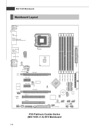
... P35 JPWR3 SYSFAN5 SATA5 SATA1 DIMM_DDR3_2 DIMM_DDR2_4 DIMM_DDR3_1 DIMM_DDR2_3 DIMM_DDR2_2 DIMM_DDR2_1 SATA2 IC IHn9tRel JB1 J B2 (optional ) I/O Chip JCOM1 Codec P CI _E 3 PCI_E4 PCI 1 PCI 2 JAUD1 JCD1 JSLIC1(ALC88 8T) JSP1 JCI1 SATA6 B AT T + IDE1 SATA7 SW1 JU SB3 JUSB2 JUSB1 SYSFAN2 FDD1 J1394_1(option al) SYSFAN3 JFP2 JFP1 P35 Platinum Combo Series (MS-7338 v1.X) ATX...
... P35 JPWR3 SYSFAN5 SATA5 SATA1 DIMM_DDR3_2 DIMM_DDR2_4 DIMM_DDR3_1 DIMM_DDR2_3 DIMM_DDR2_2 DIMM_DDR2_1 SATA2 IC IHn9tRel JB1 J B2 (optional ) I/O Chip JCOM1 Codec P CI _E 3 PCI_E4 PCI 1 PCI 2 JAUD1 JCD1 JSLIC1(ALC88 8T) JSP1 JCI1 SATA6 B AT T + IDE1 SATA7 SW1 JU SB3 JUSB2 JUSB1 SYSFAN2 FDD1 J1394_1(option al) SYSFAN3 JFP2 JFP1 P35 Platinum Combo Series (MS-7338 v1.X) ATX...
User Guide
Page 18
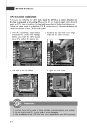
... cause the damage of socket reveal. 4. Confirm if your CPU cooler is firmly installed before installing the heat sink/cooler fan for better heat dispersion. MS-7338 Mainboard CPU & Cooler Installation W hen you install the CPU, always cover it to protect the contact from lever hinge side (as the arrow shows...
... cause the damage of socket reveal. 4. Confirm if your CPU cooler is firmly installed before installing the heat sink/cooler fan for better heat dispersion. MS-7338 Mainboard CPU & Cooler Installation W hen you install the CPU, always cover it to protect the contact from lever hinge side (as the arrow shows...
User Guide
Page 20
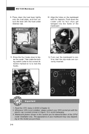
... on the model you purchase. 2-6 Mainboard photos shown in Figure 1) to fasten the cooler. Push down to avoid damaging. 3. The appearance of the mainboard. 11. MS-7338 Mainboard 9. Press the four hooks down the cooler until its four clips get wedged into the holes of your CPU socket pin with the plastic...
... on the model you purchase. 2-6 Mainboard photos shown in Figure 1) to fasten the cooler. Push down to avoid damaging. 3. The appearance of the mainboard. 11. MS-7338 Mainboard 9. Press the four hooks down the cooler until its four clips get wedged into the holes of your CPU socket pin with the plastic...
User Guide
Page 22
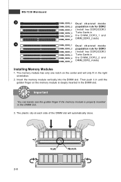
Important You can barely see the golden finger if the memory module is deeply inserted in the DIMM slot. 3. MS-7338 Mainboard 3 DIMM_DDR2_1 D u a l c h a n n e l m o d e DIMM_DDR2_2 population rule for DDR2 DIMM_DDR3_1 (Install two D DR2/D DR 3 DIMM_DDR2_3 DIMM_DDR2_4 DIMM_DDR3_2 Turbo Cards in the DIMM_D DR3_1 and DIMM_DDR3_2 slots) 4 DIMM_DDR2_1 D u a l c h a n n e l m o d e ...
Important You can barely see the golden finger if the memory module is deeply inserted in the DIMM slot. 3. MS-7338 Mainboard 3 DIMM_DDR2_1 D u a l c h a n n e l m o d e DIMM_DDR2_2 population rule for DDR2 DIMM_DDR3_1 (Install two D DR2/D DR 3 DIMM_DDR2_3 DIMM_DDR2_4 DIMM_DDR3_2 Turbo Cards in the DIMM_D DR3_1 and DIMM_DDR3_2 slots) 4 DIMM_DDR2_1 D u a l c h a n n e l m o d e ...
User Guide
Page 24
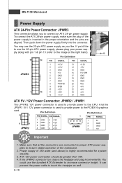
... is inserted in the proper orientation and the pins are connected to proper ATX power supplies to ensure stable operation of the power supply is used to provide power to the CPU. MS-7338 Mainboard Power Supply ATX 24-Pin Power Connector: JPWR3 This connector allows you 'd like . Then... push down the power supply firmly into the connector. ATX 12V power connection should be greater than 18A. 4. To connect ...
... is inserted in the proper orientation and the pins are connected to proper ATX power supplies to ensure stable operation of the power supply is used to provide power to the CPU. MS-7338 Mainboard Power Supply ATX 24-Pin Power Connector: JPWR3 This connector allows you 'd like . Then... push down the power supply firmly into the connector. ATX 12V power connection should be greater than 18A. 4. To connect ...

User Guide
Page 26
... or other audio devices. Rear-Surround Out in 5.1/ 7.1 channel mode. RS-Out (Black) - eSATA Port The eSATA port is a connector for different audio sound effects. MS-7338 Mainboard Audio Ports These audio connectors are used for speakers or headphones. You can differentiate the color of the audio jacks for microphones. Line-Out...
... or other audio devices. Rear-Surround Out in 5.1/ 7.1 channel mode. RS-Out (Black) - eSATA Port The eSATA port is a connector for different audio sound effects. MS-7338 Mainboard Audio Ports These audio connectors are used for speakers or headphones. You can differentiate the color of the audio jacks for microphones. Line-Out...

User Guide
Page 28
MS-7338 Mainboard Serial ATA Connector: SATA1,2,5,6,7 This connector is a high-speed Serial ATA interface port. SATA2 SATA1 SATA6 SATA5 SATA1,2,5,6 supported by ICH9R SATA7 supported by Marvell 88SE6111 Important Please do not fold the Serial ATA cable into 90-degree angle. VoIP Card Connector: JSLIC1 (Only for ALC888T) This connector connects to the instruction of the VoIP card. Otherwise, data loss may occur during transmission. Please refer to the VoIP card. JSLIC1 2 22 1 21 2-14 Each connector can connect to one Serial ATA device.
MS-7338 Mainboard Serial ATA Connector: SATA1,2,5,6,7 This connector is a high-speed Serial ATA interface port. SATA2 SATA1 SATA6 SATA5 SATA1,2,5,6 supported by ICH9R SATA7 supported by Marvell 88SE6111 Important Please do not fold the Serial ATA cable into 90-degree angle. VoIP Card Connector: JSLIC1 (Only for ALC888T) This connector connects to the instruction of the VoIP card. Otherwise, data loss may occur during transmission. Please refer to the VoIP card. JSLIC1 2 22 1 21 2-14 Each connector can connect to one Serial ATA device.

User Guide
Page 30
MS-7338 Mainboard IEEE1394 Connector: J1394_1(Optional) This connector allows you to connect the IEEE1394 device via an optional IEEE1394 bracket. 2 10 1 9 J1394_1 Pin Definition PIN SIGNAL PIN 1 TPA+ 2 3 Ground 4 5 TPB+ 6 7 Cable power 8 9 Key (no pin) 10 SIGNAL TPAGround TPBCable power Ground IEEE1394 Bracket (Optional) S/PDIF-Out Connector: JSP1 This connector is used to connect S/PDIF (Sony & Philips Digital Interconnect Format) interface for digital audio transmission. JSP1 VCC GND SPDIF 2-16 S/PDIF Bracket (Optional)
MS-7338 Mainboard IEEE1394 Connector: J1394_1(Optional) This connector allows you to connect the IEEE1394 device via an optional IEEE1394 bracket. 2 10 1 9 J1394_1 Pin Definition PIN SIGNAL PIN 1 TPA+ 2 3 Ground 4 5 TPB+ 6 7 Cable power 8 9 Key (no pin) 10 SIGNAL TPAGround TPBCable power Ground IEEE1394 Bracket (Optional) S/PDIF-Out Connector: JSP1 This connector is used to connect S/PDIF (Sony & Philips Digital Interconnect Format) interface for digital audio transmission. JSP1 VCC GND SPDIF 2-16 S/PDIF Bracket (Optional)

User Guide
Page 32
... Design Guide. 2 1 10 9 JAUD1 PIN SIGNAL 1 MIC_L 2 GND 3 MIC_R 4 PRESENCE# 5 LINE out_R 6 MIC_JD 7 Front_JD 8 NC 9 LINE out_L 10 LINEout_JD HD Audio Pin Definition DESCRIPTION Microphone - MS-7338 Mainboard Front Panel Audio Connector: JAUD1 This connector allows you to connect the front panel audio and is connected to the analog header. PRESENCE# = 0 when...
... Design Guide. 2 1 10 9 JAUD1 PIN SIGNAL 1 MIC_L 2 GND 3 MIC_R 4 PRESENCE# 5 LINE out_R 6 MIC_JD 7 Front_JD 8 NC 9 LINE out_L 10 LINEout_JD HD Audio Pin Definition DESCRIPTION Microphone - MS-7338 Mainboard Front Panel Audio Connector: JAUD1 This connector allows you to connect the front panel audio and is connected to the analog header. PRESENCE# = 0 when...
User Guide
Page 34
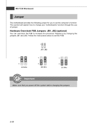
This section will explain how to increase the processor frequency by changing the jumpers JB1 and JB2. Follow the instructions below to set the computer's function. MS-7338 Mainboard Jumper The motherboard provides the following jumper for you to set the FSB. 1 3 200 MHz 1 JB1 JB2 1 3 266 MHz 1 3 333 MHz Important Make sure that you power off the system before changing the jumpers 2-20 Hardware Overclock FSB Jumpers: JB1, JB2 (optional) You can overclock the FSB to change your motherboard's function through the use of jumper.
This section will explain how to increase the processor frequency by changing the jumpers JB1 and JB2. Follow the instructions below to set the computer's function. MS-7338 Mainboard Jumper The motherboard provides the following jumper for you to set the FSB. 1 3 200 MHz 1 JB1 JB2 1 3 266 MHz 1 3 333 MHz Important Make sure that you power off the system before changing the jumpers 2-20 Hardware Overclock FSB Jumpers: JB1, JB2 (optional) You can overclock the FSB to change your motherboard's function through the use of jumper.

User Guide
Page 36
... rate. You could select the speed of the PCI_E4 slot in BIOS setup. The PCI Express x 4 slot supports up to Chapter 3 BIOS Setup - Cell Menu - MS-7338 Mainboard Slots PCI (Peripheral Component Interconnect) Express Slot The PCI Express slot supports the PCI Express interface expansion card. PCI_E1 PCI_E2 PCI_E3 PCI_E4 (Yellow) PCI...
... rate. You could select the speed of the PCI_E4 slot in BIOS setup. The PCI Express x 4 slot supports up to Chapter 3 BIOS Setup - Cell Menu - MS-7338 Mainboard Slots PCI (Peripheral Component Interconnect) Express Slot The PCI Express slot supports the PCI Express interface expansion card. PCI_E1 PCI_E2 PCI_E3 PCI_E4 (Yellow) PCI...

User Guide
Page 38
... slot is functional. LED22 Lights when PCI2 slot is functional. LED19 Lights when PCI_E3 slot is functional. 2-24 LED21 Lights when PCI1 slot is functional. MS-7338 Mainboard LED Status Indicators LED17 LED5 LED6 LED2 LED18 LED19 LED20 LED21 LED22 LED3 LED4 LED1 LED15 LED16 LED14 LED13 LED12 LED11 LED10 LED9 LED8...
... slot is functional. LED22 Lights when PCI2 slot is functional. LED19 Lights when PCI_E3 slot is functional. 2-24 LED21 Lights when PCI1 slot is functional. MS-7338 Mainboard LED Status Indicators LED17 LED5 LED6 LED2 LED18 LED19 LED20 LED21 LED22 LED3 LED4 LED1 LED15 LED16 LED14 LED13 LED12 LED11 LED10 LED9 LED8...

User Guide
Page 41
... digit refers to the model number. 6th digit refers to the chipset as I = Intel, N = nVidia, and V = VIA. 7th - 8th digit refers to the customer as MS = all standard customers. The items under continuous update for reference only. 2. Press DEL to enter SETUP If the message disappears before you respond and you...
... digit refers to the model number. 6th digit refers to the chipset as I = Intel, N = nVidia, and V = VIA. 7th - 8th digit refers to the customer as MS = all standard customers. The items under continuous update for reference only. 2. Press DEL to enter SETUP If the message disappears before you respond and you...
User Guide
Page 43
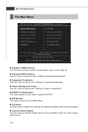
... management. Power Management Setup Use this menu to specify your settings for integrated peripherals. PNP/PCI Configurations This entry appears if your PC health status. MS-7338 Mainboard The Main Menu Standard CMOS Features Use this menu to setup the items of AMI® special enhanced features.
... management. Power Management Setup Use this menu to specify your settings for integrated peripherals. PNP/PCI Configurations This entry appears if your PC health status. MS-7338 Mainboard The Main Menu Standard CMOS Features Use this menu to setup the items of AMI® special enhanced features.
User Guide
Page 45
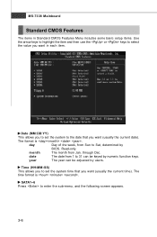
... current time). The time format is . Read-only. day Day of the week, from Sun to enter the sub-menu, and the following screen appears. 3-6 MS-7338 Mainboard Standard CMOS Features The items in each item.
... current time). The time format is . Read-only. day Day of the week, from Sun to enter the sub-menu, and the following screen appears. 3-6 MS-7338 Mainboard Standard CMOS Features The items in each item.
User Guide
Page 47
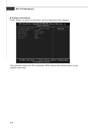
This sub-menu shows the CPU information, BIOS version and memory status of your system (read only). 3-8 MS-7338 Mainboard System Information Press to enter the sub-menu, and the following screen appears.
This sub-menu shows the CPU information, BIOS version and memory status of your system (read only). 3-8 MS-7338 Mainboard System Information Press to enter the sub-menu, and the following screen appears.
User Guide
Page 49
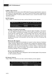
... to use only one core to be used for the operating system. To find out which MPS (Multi-Processor Specification) version to execute the instructions. MS-7338 Mainboard MPS Table Version This field allows you disable the f unction, the processor will use , consult the vendor of your operating system. W hen a malicious worm...
... to use only one core to be used for the operating system. To find out which MPS (Multi-Processor Specification) version to execute the instructions. MS-7338 Mainboard MPS Table Version This field allows you disable the f unction, the processor will use , consult the vendor of your operating system. W hen a malicious worm...


