

User Guide
Page 2
... First release for FAQ, technical guide, BIOS updates, driver updates, and other information: http://www.msi.com/index.php?func=service ◙ Contact our technical staff at: http://ocss.msi.com ii Alternatively, please try the following help resources for further guidance. ◙ Visit the MSI website for PCB 1.X Date July 2009 Technical Support If a problem arises with your system and...
... First release for FAQ, technical guide, BIOS updates, driver updates, and other information: http://www.msi.com/index.php?func=service ◙ Contact our technical staff at: http://ocss.msi.com ii Alternatively, please try the following help resources for further guidance. ◙ Visit the MSI website for PCB 1.X Date July 2009 Technical Support If a problem arises with your system and...

User Guide
Page 8
... v Chapter 1 Getting Started 1-1 Mainboard Specifications 1-2 Mainboard Layout 1-4 Packing Checklist 1-5 Chapter 2 Hardware Setup 2-1 Quick Components Guide 2-2 CPU (Central Processing Unit 2-3 Memory 2-6 Power Supply 2-8 Back Panel 2-9 Connectors 2-11 Jumpers 2-19 Switch 2-20 Slots 2-21 LED Status Indicators 2-25 Chapter 3 BIOS Setup 3-1 Entering Setup 3-2 The Main Menu 3-4 Standard CMOS Features 3-6 Advanced BIOS Features 3-9 Integrated Peripherals 3-12 Power Management Setup 3-14 H/W Monitor 3-17 Green Power 3-18 BIOS Setting Password 3-19 Cell Menu 3-20 viii
... v Chapter 1 Getting Started 1-1 Mainboard Specifications 1-2 Mainboard Layout 1-4 Packing Checklist 1-5 Chapter 2 Hardware Setup 2-1 Quick Components Guide 2-2 CPU (Central Processing Unit 2-3 Memory 2-6 Power Supply 2-8 Back Panel 2-9 Connectors 2-11 Jumpers 2-19 Switch 2-20 Slots 2-21 LED Status Indicators 2-25 Chapter 3 BIOS Setup 3-1 Entering Setup 3-2 The Main Menu 3-4 Standard CMOS Features 3-6 Advanced BIOS Features 3-9 Integrated Peripherals 3-12 Power Management Setup 3-14 H/W Monitor 3-17 Green Power 3-18 BIOS Setting Password 3-19 Cell Menu 3-20 viii
User Guide
Page 11
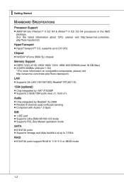
...; Supports 2 IEEE1394 ports (rear x1, front x1) Audio ■ Chip integrated by Realtek® ALC889 ■ Flexible 8-channel audio with jack sensing ■ Compliant with Azalia 1.0 Spec IDE ■ 1 IDE port ■ Supports Ultra DMA 66/100/133 mode ■ Supports PIO, Bus Master operation mode SATA ■ 6 SATAII ports ■ Supports storage and data transfers at up to 3 Gb/s RAID ■ 6 SATAII ports support RAID 0/ 1/ 0+1/ 5 or JBOD mode 1-2 ▍ Getting Started Mainboard Specifications Processor Support ■ AMD® 64 bits...
...; Supports 2 IEEE1394 ports (rear x1, front x1) Audio ■ Chip integrated by Realtek® ALC889 ■ Flexible 8-channel audio with jack sensing ■ Compliant with Azalia 1.0 Spec IDE ■ 1 IDE port ■ Supports Ultra DMA 66/100/133 mode ■ Supports PIO, Bus Master operation mode SATA ■ 6 SATAII ports ■ Supports storage and data transfers at up to 3 Gb/s RAID ■ 6 SATAII ports support RAID 0/ 1/ 0+1/ 5 or JBOD mode 1-2 ▍ Getting Started Mainboard Specifications Processor Support ■ AMD® 64 bits...

User Guide
Page 24
... high-definition video, plus multi-channel digital audio on a single cable. ▶ 1394 Port (optional) The IEEE1394 port on the back panel provides connection to IEEE1394 devices. ▶ USB Port The USB (Universal Serial Bus) port is provided for monitor. ▶ DVI-D Port The DVI-D (Digital Visual Interface-Digital) connector allows you to connect a LCD monitor. To connect an LCD monitor, simply plug your monitor cable into the DVI-D connector, and make sure that the other USB-compatible devices. 2-9 It provides a high-speed...
... high-definition video, plus multi-channel digital audio on a single cable. ▶ 1394 Port (optional) The IEEE1394 port on the back panel provides connection to IEEE1394 devices. ▶ USB Port The USB (Universal Serial Bus) port is provided for monitor. ▶ DVI-D Port The DVI-D (Digital Visual Interface-Digital) connector allows you to connect a LCD monitor. To connect an LCD monitor, simply plug your monitor cable into the DVI-D connector, and make sure that the other USB-compatible devices. 2-9 It provides a high-speed...

User Guide
Page 26
... install two IDE devices on the same cable, you must configure the drives separately to IDE device's documentation supplied by setting jumpers. MS-7612 Connectors Floppy Disk Drive Connector: FDD1 This connector supports 360 KB, 720 KB, 1.2 MB, 1.44 MB or 2.88 MB floppy disk drive. Fl opMpySDI Kdkldkddfkkakfskkdskkdakaddfdddffdfkad-dkdffdldkddjadfdsdddjfdddffkadasdfdddffdfadasfsadfddsddadasdsaddsdafsddadsdddfdsadddfffaffsfsdasfdfffdf 5 D 1i s/k4"DFr il voeppCyonnect or 3 1/2" F l oppy D i sk D r i ve Connector 3 1/2" F l oppy D i sk D ri ve Connector IDE Connector: IDE1 This connector...
... install two IDE devices on the same cable, you must configure the drives separately to IDE device's documentation supplied by setting jumpers. MS-7612 Connectors Floppy Disk Drive Connector: FDD1 This connector supports 360 KB, 720 KB, 1.2 MB, 1.44 MB or 2.88 MB floppy disk drive. Fl opMpySDI Kdkldkddfkkakfskkdskkdakaddfdddffdfkad-dkdffdldkddjadfdsdddjfdddffkadasdfdddffdfadasfsadfddsddadasdsaddsdafsddadsdddfdsadddfffaffsfsdasfdfffdf 5 D 1i s/k4"DFr il voeppCyonnect or 3 1/2" F l oppy D i sk D r i ve Connector 3 1/2" F l oppy D i sk D ri ve Connector IDE Connector: IDE1 This connector...

User Guide
Page 28
... Connector: JCD1 This connector is the positive and should be connected to the +12V; When connecting the wire to the connectors, always note that will automatically control the CPU fan speed according to GND. You can install Overclocking Center utility that the red wire is provided for proper CPU cooling fan. • CPUFAN1 supports fan control. MS-7612 Fan Power Connectors: CPUFAN1, SYSFAN1~3 The fan power connectors support system cooling fan with speed sensor to the recommended CPU fans at processor...
... Connector: JCD1 This connector is the positive and should be connected to the +12V; When connecting the wire to the connectors, always note that will automatically control the CPU fan speed according to GND. You can install Overclocking Center utility that the red wire is provided for proper CPU cooling fan. • CPUFAN1 supports fan control. MS-7612 Fan Power Connectors: CPUFAN1, SYSFAN1~3 The fan power connectors support system cooling fan with speed sensor to the recommended CPU fans at processor...

User Guide
Page 34
Then return to clear data. 1 JBAT1 1 Keep Data 1 Clear Data Important You can automatically boot OS every time it will damage the mainboard. 2-19 it is a CMOS RAM onboard that has a power supply from an external battery to keep the data of system configuration. If you want to clear the system configuration, set the jumper to 1-2 pin position. Avoid clearing the CMOS while the system is off. MS-7612 Jumpers Clear CMOS Jumper: JBAT1 There is turned on ; With the CMOS RAM, the system can clear CMOS by shorting 2-3 pin while the system is on .
Then return to clear data. 1 JBAT1 1 Keep Data 1 Clear Data Important You can automatically boot OS every time it will damage the mainboard. 2-19 it is a CMOS RAM onboard that has a power supply from an external battery to keep the data of system configuration. If you want to clear the system configuration, set the jumper to 1-2 pin position. Avoid clearing the CMOS while the system is off. MS-7612 Jumpers Clear CMOS Jumper: JBAT1 There is turned on ; With the CMOS RAM, the system can clear CMOS by shorting 2-3 pin while the system is on .

User Guide
Page 36
... Slot PCI (Peripheral Component Interconnect) Slot The PCI slot supports LAN card, SCSI card, USB card, and other add-on cards that comply with PCI specifications. 32-bit PCI Slot Important When adding or removing expansion cards, make sure that you unplug the power supply first. The PCI IRQ pins are hardware lines over which devices can send interrupt signals to the microprocessor. Meanwhile, read the documentation for the expansion card to the PCI bus pins as jumpers, switches or BIOS configuration. PCI...
... Slot PCI (Peripheral Component Interconnect) Slot The PCI slot supports LAN card, SCSI card, USB card, and other add-on cards that comply with PCI specifications. 32-bit PCI Slot Important When adding or removing expansion cards, make sure that you unplug the power supply first. The PCI IRQ pins are hardware lines over which devices can send interrupt signals to the microprocessor. Meanwhile, read the documentation for the expansion card to the PCI bus pins as jumpers, switches or BIOS configuration. PCI...

User Guide
Page 37
... to connect a monitor to the following instructions. 1. Install two graphics cards on the first card will work. Please note that you connect an adequate power supply to the power connector on the first PCIE x16 (PCI_E2) slot. 2-22 SLI Video Link Card If you intend to the picture below). To utilize this section are of a single graphics card. Hence, you have installed two graphics cards, only the video outputs on PCI Express x16 slots. ▍ Hardware Setup NVIDIA® SLI Technology...
... to connect a monitor to the following instructions. 1. Install two graphics cards on the first card will work. Please note that you connect an adequate power supply to the power connector on the first PCIE x16 (PCI_E2) slot. 2-22 SLI Video Link Card If you intend to the picture below). To utilize this section are of a single graphics card. Hence, you have installed two graphics cards, only the video outputs on PCI Express x16 slots. ▍ Hardware Setup NVIDIA® SLI Technology...

User Guide
Page 39
... to connect a monitor to provide higher performance (GeForce Boost) Hybrid-Power Mode - The Hybrid modes are simultaneously active and working collaboratively to the onboard video output. 2-24 The chipset will work. Important Please note that the system is in the PCI Express slot, only the onboard video outputs (which supports Windows Vista only. Enabling Hybrid SLI Technology Power off and mGPU renders and drives the display (HybridPower). Hence, you have installed the graphics card in Performance mode...
... to connect a monitor to provide higher performance (GeForce Boost) Hybrid-Power Mode - The Hybrid modes are simultaneously active and working collaboratively to the onboard video output. 2-24 The chipset will work. Important Please note that the system is in the PCI Express slot, only the onboard video outputs (which supports Windows Vista only. Enabling Hybrid SLI Technology Power off and mGPU renders and drives the display (HybridPower). Hence, you have installed the graphics card in Performance mode...

User Guide
Page 48
... when you connect the HD devices to the IDE/ SATA/ E-SATA connectors on the mainboard. ▶ Floppy Drive A This item allows you an opportunity to move data from a hard disk that is going to fail to a safe place before the hard disk becomes offline. Setting to Auto enables LBA mode if the device supports it and the devices is a utility that monitors your disk status to predict hard disk failure. This gives you to set the type of floppy drives installed. 3-7 This...
... when you connect the HD devices to the IDE/ SATA/ E-SATA connectors on the mainboard. ▶ Floppy Drive A This item allows you an opportunity to move data from a hard disk that is going to fail to a safe place before the hard disk becomes offline. Setting to Auto enables LBA mode if the device supports it and the devices is a utility that monitors your disk status to predict hard disk failure. This gives you to set the type of floppy drives installed. 3-7 This...
User Guide
Page 51
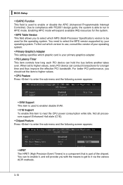
... over. When set the item to higher values. ▶ CPU Feature Press to enter the sub-menu and the following screen appears: ▶ HPET The HPET (High Precision Event Timers) is a component that is part of your operating system. For better PCI performance, you to select which graphic card is able to be used to enable/ disable SVM. ▶ C1E Support To enable this item...
... over. When set the item to higher values. ▶ CPU Feature Press to enter the sub-menu and the following screen appears: ▶ HPET The HPET (High Precision Event Timers) is a component that is part of your operating system. For better PCI performance, you to select which graphic card is able to be used to enable/ disable SVM. ▶ C1E Support To enable this item...

User Guide
Page 53
...; BIOS Setup Integrated Peripherals ▶ USB Controller This setting allows you to enable/disable the onboard USB 1.1/ 2.0 controller. ▶ USB Device Legacy Support Select [Enabled] if you need to use a USB-interfaced device in the operating system. ▶ Onboard Controller This setting allows you to enable/disable the onboard LAN controller. ▶ LAN Option ROM This item is used to decide whether to invoke the Boot ROM of the onboard LAN. ▶ Onboard IEEE1394 Controller This setting is used to enable/disable the onboard IEEE 1394 controller. ▶ HD Audio Controller This...
...; BIOS Setup Integrated Peripherals ▶ USB Controller This setting allows you to enable/disable the onboard USB 1.1/ 2.0 controller. ▶ USB Device Legacy Support Select [Enabled] if you need to use a USB-interfaced device in the operating system. ▶ Onboard Controller This setting allows you to enable/disable the onboard LAN controller. ▶ LAN Option ROM This item is used to decide whether to invoke the Boot ROM of the onboard LAN. ▶ Onboard IEEE1394 Controller This setting is used to enable/disable the onboard IEEE 1394 controller. ▶ HD Audio Controller This...

User Guide
Page 54
... to enable/ disable BIOS to used to select mode for SATA connectors. ▶ I /O chipset that provides Standard, ECP, and EPP features. To operate the onboard parallel port in ECP mode only. MS-7612 ▶ On-Chip IDE Controller The integrated peripheral controller contains a IDE interface with support for the serial port. ▶ Parallel Port There is used PCI busmastering for reading/ writing to IDE drives. ▶ On-Chip SATA Controller This item allows users to enable or disable the SATA controller. ▶ RAID Mode...
... to enable/ disable BIOS to used to select mode for SATA connectors. ▶ I /O chipset that provides Standard, ECP, and EPP features. To operate the onboard parallel port in ECP mode only. MS-7612 ▶ On-Chip IDE Controller The integrated peripheral controller contains a IDE interface with support for the serial port. ▶ Parallel Port There is used PCI busmastering for reading/ writing to IDE drives. ▶ On-Chip SATA Controller This item allows users to enable or disable the SATA controller. ▶ RAID Mode...
User Guide
Page 55
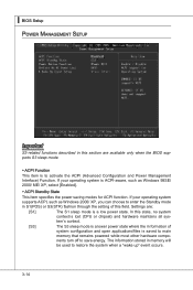
... system supports ACPI, such as Windows 98SE/ 2000/ ME/ XP, select [Enabled]. ▶ ACPI Standby State This item specifies the power saving modes for ACPI function. tem's context. [S3] The S3 sleep mode is a lower power state where the in formation of this field. ▍ BIOS Setup Power Management Setup Important S3-related functions described in this section are : [S1] The S1 sleep mode is a low power state. Settings...
... system supports ACPI, such as Windows 98SE/ 2000/ ME/ XP, select [Enabled]. ▶ ACPI Standby State This item specifies the power saving modes for ACPI function. tem's context. [S3] The S3 sleep mode is a lower power state where the in formation of this field. ▍ BIOS Setup Power Management Setup Important S3-related functions described in this section are : [S1] The S1 sleep mode is a low power state. Settings...

User Guide
Page 56
... before power failure or interrupt occurred. ▶ Wake Up Event Setup Press and the following sub-menu appears. ▶ Wake up Event By Setting to [BIOS] activates the following fields, and use the following fields to be awakened from what power saving modes when input signal of the PS/2 keyboard/ mouse is turned off button. [Suspend] When you press the power button, the computer enters suspend/ sleep mode, but...
... before power failure or interrupt occurred. ▶ Wake Up Event Setup Press and the following sub-menu appears. ▶ Wake up Event By Setting to [BIOS] activates the following fields, and use the following fields to be awakened from what power saving modes when input signal of the PS/2 keyboard/ mouse is turned off button. [Suspend] When you press the power button, the computer enters suspend/ sleep mode, but...

User Guide
Page 58
... Health Status ▶ CPU/ System Temperature, CPU FAN/ SYS FAN 1/ SYS FAN2 Speed, CPU Vcore, 3.3V, 5V, 12V These items display the current status of all of the monitored hardware devices/components such as CPU voltage, temperatures and all fans' speeds. 3-17 It provides several sections to speed up for cooling down automatically. ▶ SYS FAN 1/ 2 Control This item allows users to [Reset]. The setting of recording the chassis intrusion status and...
... Health Status ▶ CPU/ System Temperature, CPU FAN/ SYS FAN 1/ SYS FAN2 Speed, CPU Vcore, 3.3V, 5V, 12V These items display the current status of all of the monitored hardware devices/components such as CPU voltage, temperatures and all fans' speeds. 3-17 It provides several sections to speed up for cooling down automatically. ▶ SYS FAN 1/ 2 Control This item allows users to [Reset]. The setting of recording the chassis intrusion status and...

User Guide
Page 69
... using [ROM] as default name. ▶ Start to save file Press "Enter" and select "OK" the system will stare to save it only supports FAT/ FAT32 file system drive. ▶ Save File Name as Please setup a specific name for booting. ▶ Load BIOS source file from the USB/ Storage (FAT/32 format only) drive. == Backup BIOS to USB drive == The following fields are used to read the onboard BIOS ROM data, and save the onboard ROM chip data to [BIOS Update...
... using [ROM] as default name. ▶ Start to save file Press "Enter" and select "OK" the system will stare to save it only supports FAT/ FAT32 file system drive. ▶ Save File Name as Please setup a specific name for booting. ▶ Load BIOS source file from the USB/ Storage (FAT/32 format only) drive. == Backup BIOS to USB drive == The following fields are used to read the onboard BIOS ROM data, and save the onboard ROM chip data to [BIOS Update...

User Guide
Page 96
... (RAID 0+1), RAID 5 or JBOD and create the desired RAID array. 3. Entering the RAID BIOS Setup 1. The default RAID Mode is set to Mirroring and Striping Block is set up the NVRAID BIOS. Boot from the Windows CD, use the floppy disk that are to be RAID enabled in the system BIOS. (Refer the bios section for details.) 2. Bootable RAID Array 1. Initialize the NVRAID Array Disks. The PC will appear. Press F10, and the NVIDIA RAID Utility --- Setting...
... (RAID 0+1), RAID 5 or JBOD and create the desired RAID array. 3. Entering the RAID BIOS Setup 1. The default RAID Mode is set to Mirroring and Striping Block is set up the NVRAID BIOS. Boot from the Windows CD, use the floppy disk that are to be RAID enabled in the system BIOS. (Refer the bios section for details.) 2. Bootable RAID Array 1. Initialize the NVRAID Array Disks. The PC will appear. Press F10, and the NVIDIA RAID Utility --- Setting...

User Guide
Page 100
... location to install Windows Vista, please click on the "Load Driver" button to leave the floppy disk inserted in the \\nVidia\System\MCP72\IDE\WinXP\Sataraid\Floppy to continue with Windows XP Installation. Select "NVIDIA NForce Storage Controller" and then press ENTER. 8. Follow the instructions on the Setup screen. If this is done. 4. You should be prompted to a medium (floppy disk/ CD/DVD or USB). b] Click the "Browse DVD" on how to supply the driver...
... location to install Windows Vista, please click on the "Load Driver" button to leave the floppy disk inserted in the \\nVidia\System\MCP72\IDE\WinXP\Sataraid\Floppy to continue with Windows XP Installation. Select "NVIDIA NForce Storage Controller" and then press ENTER. 8. Follow the instructions on the Setup screen. If this is done. 4. You should be prompted to a medium (floppy disk/ CD/DVD or USB). b] Click the "Browse DVD" on how to supply the driver...


